
Abstract
A novel cylindrical ultrasonic motor easy to be fixed is proposed in this article. There are threaded holes on the bottom of stator used for fixing, distinguishing it from other cylindrical stators. The bottom is machined as a round lug boss. Its radius is smaller than the inner radius of the stator in order not to affect the excitation of vibration mode. The finite element analysis was accomplished to verify the working principle. Based on the analysis, a prototype was fabricated and measured. The mechanical output characteristics were obtained by experiments. The maximal velocity of the proposed motor is 170 r/min at the operating frequency of 31.6 kHz.
Introduction
Ultrasonic motors, driven by ultrasonic vibration instead of electromagnetic force, have superior characteristics such as simple structure without coils, low-speed without reducer, self-locking in the power-off state, and absence of electromagnetic radiation.1–3 These more competitive merits make them good candidates for robots, 4 high-precision machines, 5 surgery devices, 6 and optical instruments. 7
Ultrasonic motor can be classified into two major groups: standing wave and traveling wave type, based on the vibration type of stator. Traveling-wave-type ultrasonic motors utilize the characteristics of rotational symmetric structure (such as ring or a bar), which is the existence of two orthogonal bending modes with the same eigenfrequency. Traveling wave can generated by superposing the two modes.8–10 Then, the rotation movement of rotor can be produced via the friction between stator and rotor. Traveling-wave ultrasonic motor can simplify the eigenfrequency matching processing due to the structure symmetry.
Cylindrical ultrasonic motor, as a kind of traveling wave ultrasonic motor, has been widely investigated. According to the lead zirconate titanate (PZT) working mode, cylindrical ultrasonic motor can be classified into bolt-clamped-type motors11–14 and bonded-type motors.15–19 Bolt-clamped-type ultrasonic motors utilize one or more transducers to construct the stator. To excite traveling wave on the stator, the longitudinal vibration mode with spatial phase shift11,12 or the hybrid of longitudinal-bending vibration mode13,14 are utilized. Although bolt-clamped-type motors utilizing d33 mode of PZT exhibit higher output power and efficiency than bonded-type motors utilizing d31 mode, the bonded-type structure is more suitable for miniaturization without the limitation of bolt connection. The bonded-type motors can be divided into two types. One utilizes bonded-type transducer to excite the traveling wave on a cylindrical stator.15,16 Due to the existence of transducer, this kind of motor is still not suitable for miniaturization. The other utilizes PZTs bonded to the outside wall of a cylindrical stator to excite the traveling wave.17–20 Although this type ultrasonic motor achieves miniaturization, its vibration nodes are often on the surface of the cylindrical stator, which makes it inconvenient for installation and fixing, especially in the application of large-scale arrays. C Zhao has designed a noncontact ultrasonic motor which utilizes B03 bending modes of cylinder stator. However, an elastic cushion is utilized to achieve the free–free boundary at the two ends of the stator. 1 It increases the complexity of the fixing, making it inconvenient for industrial application.
The cylindrical ultrasonic motor presented in this article aims to solve the problem of the inconvenient fixing. The stator is constructed by bonding PZTs to a metal base. There are threaded holes on the bottom of stator for fixing, which distinguish it from other cylindrical stators. The bottom of the stator is machined as a round boss, whose radius is smaller than the inner radius of the stator, so that the excitation of vibration mode will be not affected. The proposed motor operates in the hybrid of two orthogonal B03 bending modes of the cylinder. This motor achieves convenient fixing, and the relative details will be explained in this article.
Structure and operating principle
The cylinder-shaped stator is composed of four pieces of piezoelectric ceramics and one brass short cylinder, shown in Figure 1. Outside surface of the cylinder was flattened on four sides at 90° to each other, and four uniformly rectangular piezoelectric ceramics are bonded onto these flattened surfaces. The parallel piezoelectric ceramics have the same polarization direction, shown in Figure 1(a) by arrows. For the convenience of the installation and fixing, the cylindrical stator is designed like a bucket. There are threaded holes for fixing at the bottom of the bucket. The bottom of the stator is machined as a round boss, as shown in Figure 1(b). The basic configuration of the motor is composed of a base, a cylindrical stator, a rotor, a spring, and a nut, as shown in Figure 1(c). The cone-shaped rotor is pressed on the stator. The nut is screwed to the end of the shaft and used to press rotor. The preload between the rotor and stator can be adjusted by changing the nut location. The stator is fastened on the base via screws, which is more stable in industrial application compared with structure in Zhao. 1 Also, the radius of the round boss is smaller than the inner radius of the stator so that mounting face will not hinder the vibration of the stator, which distinguishes it from the motor in Zhao. 1

Structures of stator and ultrasonic motor: (a) main view of the stator, (b) another view of the stator, and (c) structure of ultrasonic motor.
The proposed motor utilizes the hybrid of two orthogonal B03 bending modes to generate the traveling wave on the surface of the stator. Bmn means the bending vibration modal of cylinder, where m and n indicate nodal circles and diameters, respectively. The two orthogonal B03 bending vibration modes have the same resonance frequency due to the structure symmetry. When applied sine and cosine electric signals with the same frequency close to the eigenfrequency of B03 mode through Phase A and Phase B simultaneously, two standing waves of B03 bending mode with a spatial phase difference of 1/4 wavelength are excited and coupled, as shown by the solid line and the dotted line in Figure 2. It will result in the traveling wave on the surface of stator.

Working principle of the stator.
Design and analysis
FEM software ANSYS 14 is used to confirm the vibration mode and modal frequency of the stator. During the calculation, brass (Young’s modulus E = 92 GPa, Poisson ratio σ = 0.33, and density ρ = 8270 kg/m3) is selected for cylindrical stator and the PZT-4 with density 7600 kg/m3 is selected as piezoelectric components. The piezoelectric matrix e, stiffness matrix cE, and the dielectric matrix εT of PZT-4 are listed in Table 1:
Parameters of piezoelectric ceramics PZT-4.

Compared with other cylindrical ultrasonic motors, the feature of the stator is that the bottom has threaded holes for fixing. The original structure of the stator is like a regular bucket. The inner diameter, outer diameter, and the thickness of the bottom are 13, 15, and 1 mm, respectively. The resonant frequency of the original structure is 36.95 kHz, as shown in Figure 3(a). Three wavelengths along its circumference demonstrate the working principle. However, there is partial vibration at the bottom of the stator resulting from B03 bending vibration, as shown in Figure 3(b). Actually, the bottom of stator, as the mounting face in our design, should not have any vibrations, or it will hinder the vibration. So, the structure of the stator is adjusted, as shown in Figure 1. The bottom is machined into a round boss. Its radius r3 is smaller than the inner radius of the stator r1 so that the working mode will not lead to partial vibration at the mounting surface, as shown in Figure 3(c). Table 2 lists the final structural parameters. The thickness of PZT is 0.5 mm, and the resonance frequency is 36.07 kHz.

Modal analysis of stators: (a) mode shape of original structure, (b) another view of the mode shape and (c) mode shape of adjusted structure.
Parameters of the stator (mm).

To further confirm whether mounting surface will hinder the vibration of the stator, transient analysis was accomplished by applying sine and cosine exciting voltages with amplitude 100V0-p and frequency of 36 kHz on the two groups of PZTs simultaneously. Particle A at the driving surface and particle B at rim of mounting surface were selected, as shown in Figure 1. Their movements during a vibration period in xoy plane were extracted and plotted, as shown in Figure 4(a). It indicates that motion trajectory of selected particle A is ellipse, which is consistent with the working principle. At the same time, there is almost no vibration at particle B, indicating that it is reasonable to use the bottom surface as mounting surface. As a comparison, another transient analysis was also accomplished to test the vibration characteristics of the original stator. Two particles C and D on the driving surface and mounting surface, respectively, were selected, as shown in Figure 3(a) and (b). Their movements in one vibration period were shown in Figure 4(b). The particle D on the mounting surface has a small elliptical motion trajectory, which means that the bottom surface of the original structure is not suitable as a mounting surface. Moreover, the vibration amplitudes in the x and y directions of the driving particle C are 1 and 0.58 μm. The corresponding amplitudes of particles A have reached 1.45 and 0.8 μm after improvement, as shown in Figure 4(a). It means that that the adjusted stator enhances the output characteristics of the motor.

Motion trajectories of selected particles: (a) after adjustment and (b) before adjustment.
Experiment
To validate the feasibility of the proposed design, a prototype motor was fabricated based on the structure parameters listed in Table 1, as shown in Figure 5. The four pieces of PZT piece were bonded onto the four flat surfaces by epoxy adhesive. The precision parallel-jaw was used to clamp them for about 12 h to accomplish the solidification process. The mass of the stator is 2.56 g, and the motor weighs 4.1 g.
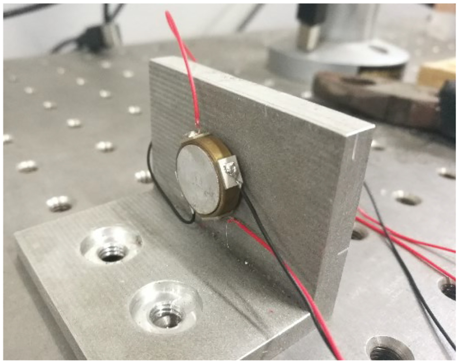
The prototype of proposed motor.
To verify the vibration performance of the stator, the resonance frequency and the associated admittance of the stator were tested by an LCR meter (4100; Wayne Kerr Electronics, USA). Two electrodes of PZT in Phase A or Phase B were connected to high terminal, with the other piezoelectric ceramics keeping open circuit. The metal body was connected to the low terminal of the LCR meter. The impedance–frequency curves are obtained and shown in Figure 6. There are mutations in the curve, though it is not obvious, indicating that the resonant frequencies of Phase A and Phase B are 32 kHz. There are deviations between simulation and experimental results, but the two vibration mode frequencies are consistent, which means the excitation of the traveling wave on the driving surface is feasible. The deviation might be caused by the machining and assembly errors, the nonuniform adhesive strength between piezoelectric ceramics and the stator, and the differences between the real materials and the idea model. In addition, the piezoelectric ceramics are cut up manually, which increases the error.

Admittance and phase characteristics of the stator versus frequency: (a) Phase A and (b) Phase B.
However, the frequency accuracy of the LCR meter is only 500 Hz, indicating that the actually resonant frequency of the stator may not be 32 kHz, but at a certain frequency close to 32 kHz. So, the speed–frequency characteristic of the motor was investigated to find the optimal one. The tested frequency range is 29–34 kHz with the intervals of 0.2 kHz (two applied voltage of 150V0-p with a temporal phase difference of 90°). The preload was adjusted by the spring (about 25 mN). The speed of the rotor was measured via laser speedometer. Figure 7 shows the experimental result. The maximum speed of 148 r/min is achieved at the operating frequency of 31.6 kHz. Compared with the resonant frequency tested in last section, the driven frequency shifts by 0.4 kHz, which is caused by inaccurate measuring instrument and installation of the stator. Besides frequency of 31.6 kHz, the curve has another peak at frequency of 30.8 kHz, corresponding to the speed of 139 r/min. Although the impedance test result shows that the resonant frequencies of two B03 modes are 32 kHz, actually, there may be inconsistencies between the two orthogonal B03 modes due to the LCR meter accuracy limitation. The two peaks might be caused by the frequency inconsistency. The stall torque of the ultrasonic motor is approximately 0.06 mN m at the optimum operating frequency, which is tested by adding weight at the shaft through a string–wheel system.

Plot of the speed versus exciting frequency.
Then, the exciting voltage amplitude was changed to obtain its effect on the output speed (with frequency of 31.6 kHz and phase shift of 90°), as shown in Figure 8. The motor achieves a maximum speed of 158 r/min under exciting voltage of 175V0-p. The amplitude of exciting voltages shows nearly linear relationship with the speed, so it can be used to control output speed.

Plot of the speed versus exciting voltage.
Also, the relationship between the phase shift of two signals (excited frequency of 31.6 kHz and voltage of 150V0-p) and speed was investigated, as shown in Figure 9. The positive and negative of the rotation speed represent clockwise and counterclockwise, respectively. It is obvious that the maximum clockwise speed reaches up to 161 r/min and the maximum counterclockwise speed reaches up 170 r/min with phase shifts 120° and −60°, respectively. In theory, the speed of counterclockwise or clockwise reaches to maximum with phase shift 90° or −90°. The deviations also might be caused by the machining and assembly errors, the differences between the real materials and the idea model, and so on.

Plot of the speed versus phase shift.
Actually, the rotor was put on the stator directly during the experiment with no friction materials. Under this condition, there were obvious scratches on the surface of the rotor. And, filings were seen on the interfaces of the stator. In future, the friction material can be added to the surface of the rotor to improve the wear problem. Also, the output force is too small to be applied in industrial application currently. It can be improved with following methods in future: (1) the friction coefficient can be increased by adding the friction materials; (2) the mutations in impedance curves are not obvious enough, indicating that the vibration of the stator is imperfect. It can be improved by improving the manufacturing processing; (3) the electromechanical coupling factor can be taken into consideration in future to improve the output force.
Conclusion
In summary, a novel cylindrical ultrasonic motor easy to be fixed is proposed, designed, and fabricated in this article. Two orthogonal B03 bending vibration modes of the stator were generated with temporal shift of 90° to produce elliptical movement on the driving surface. There are threaded holes on the bottom of stator for fixing. In order not to influence the vibration excitation of the stator, the bottom of the stator is machined to a round boss with smaller radius compared with the inner radius. The weight of the proposed stator and motor is only 2.56 and 4.1 g, respectively. It achieves a maximum speed of 170 r/min under working frequency of 31.6 kHz. The proposed motor can be further improved by improving its structure and manufacturing processing due to its small stall torque. The proposed motor has a simple fixing process, and it has a potential to be applied to in large-scale arrays operation.
Footnotes
Handling Editor: Farzad Ebrahimi
Declaration of conflicting interests
The author(s) declared no potential conflicts of interest with respect to the research, authorship, and/or publication of this article.
Funding
The author(s) disclosed receipt of the following financial support for the research, authorship, and/or publication of this article: This work was supported by the National Natural Science Foundation of China (No. 51505204).