
Abstract
Chain drive is one of the most commonly used mechanical devices in the main equipment transmission system. In the past decade, scholars focused on basic performance research, but ignore its best performance. In this study, due to the large vibration of the chain drive in the transmission system, the vibration performance and optimization parameters are also considered as a new method to design the chain drive system to obtain the best performance of the chain drive system. This article proposes a new method and takes a chain drive design as a case based on the multidisciplinary design optimization. The system optimization objective and sub-systems are established by the multidisciplinary design optimization method. To obtain the best performance for the chain, the chain drive is executed by an improved particle swarm optimization algorithm. Dynamic characteristics of the chain drive system are simulated based on the multidisciplinary design optimization results. The impact force of the chain links, vibration displacement, and the vibration frequency are analyzed. The results show that the kinematics principle of the chain drive and the optimal parameter value are obtained based on the multidisciplinary design optimization method.
Introduction
The economy of the state is dominated by industrial production. Transmission system is the core component of the industrial products. Chain drive system is one of the ways to deliver power, which is used in the conditions of high-speed, overload, variable speed, and load. 1 The complex multi-body system of a chain drive can cause undesirable noises, especially if the occurring frequencies excite adjacent structures. 2 The transverse vibration of the chain drive directly affects the performance of the equipment. The conventional design only considers the basic performance of the chain drive system, but ignores its best performance. Test experiments of the device performance are usually done after the mechanical structure design. In recent years, many researchers have focused on the vibration performance. For example, Liu et al. 3 concentrated on chain drive vibrations and their theoretical prediction. Feng et al. 4 used the virtual prototyping technology to analyze the meshing of new silent chain and sprockets. Rega5,6 and Ibrahim 7 reviewed the transverse vibrations of axially moving strings. Machado et al. 8 and Feng 9 researched the meshing characteristic of chain drive system based on the silent chain simulation models. Cheng used multi-body dynamics to analyze the transverse fluctuations of axial moving of silent chain. 10 Pereira 11 built an automatic multi-body model of chain transmission and obtained the kinematics regularity. It is observed that all the above transverse vibration analyses only focus on the existing structure rather than considering optimization issues.
Noguchi 12 developed some methods of weight saving for the chain drive system based on the finite element method analysis. In the proposed design, the weight is reduced by 10%, but the stress is only 3% higher than the previous studies. Burgess and Lodge 13 and Tushar 14 investigated the optimization of the chain drive system on sports motorcycles. Flores investigated the optimization of the chain transmission system which is on the sports motorcycles. 15 The results show that the performance parameters of the chain drive have a great influence on the transmission efficiency. Sergeev and Moskalev 16 analyzed the coupling geometry and parametric optimization of the sprocket. The above studies have focused on the optimization of the existing chain drive system while ignoring the effects of different disciplines. In this article, the multidisciplinary design optimization (MDO) method is proposed, which takes into account the effect of the design parameter on the vibration performance in the design of the chain transmission system.
The reminder of the article is organized as follows. Section “Vibration model of the chain drive” discusses the influence of impact force on vibration and the natural frequency of transmission vibration of a chain drive system. The MDO method is introduced in section “The establishment of the dynamic model,” including the optimization objective and the restrictions. Section “Dynamic simulation of the chain belt drive” establishes the dynamical model. The transverse vibration performance is discussed in section “Results”. Section “Future work” gives the concluding remarks.
Vibration model of the chain drive
Chain drive is a common transmission in a mechanical device that is primarily used for the transmission of power from the driving sprocket to the driven sprocket. Compared with the belt drive and gear drive, the chain drive system has many advantages.
Comparison of chain drive and belt drive:
The chain drive has no elastic sliding and can maintain an accurate average transmission ratio, so the transmission efficiency of the chain drive system is higher.
The belt drive requires a large tension, and the shaft and bearing need to bear a larger load; however, the chain drive is the opposite.
The chain drive system is reliable and can work under low-speed heavy load.
Comparison of chain drive and gear drive:
The chain drive can have a larger center distance.
Gear drive is usually in a closed clean environment, but the chain drive usually works in high-temperature environment, humid environment, and dusty environment.
The cost of the chain drive system is low.
Although the chain drive has the above advantages, there are still many shortcomings, such as (a) the change in the instantaneous speed and instantaneous transmission ratio, (b) poor transmission stability, and (c) it is not suitable for occasions, with the influence of work and noise and often changes the direction of transmission. To study the dynamic performance of the chain drive system, the theoretical model and the kinematics equation of the chain drive are established.
Chain drive is usually composed of driving sprocket and the driven sprocket. The driving sprocket is driven by the motor. To study the kinetic characteristics of the chain drive, the Cartesian coordinate system is established in the center of the driving sprocket.

Transverse vibrations model of the chain drive system.
The impact force of the chain drive system
Chain drive is not only suitable for low-speed applications but also can be effectively used in high-speed transmission occasions. For high-speed applications, the meshing impact load between the chain and the sprocket is the main reason to cause the vibration of the chain drive. The following equations can be obtained according to the relationships between the meshing impact force of the chain drive, the number of teeth of sprockets, the chain pitch, and the stiffness coefficient. The impact load between the chain and the sprocket can be given by

The impact loads between the chain and the sprockets are the main reason to cause the transverse vibration. In this study,

where
By substituting equations (2) and (3) into equation (8), the equation of

where

The natural frequency of transmission vibration of the chain drive
The natural frequency is a very important parameter for mechanical systems. When the object is free to vibrate, its displacement changes with time according to the sine or cosine law. The frequency is independent of the initial condition, which is only related to the inherent characteristics of the system. The natural frequency of each order corresponds to a vibration mode.
To investigate the natural vibration of the transmission vibration and the natural frequency of the chain drive, the natural frequency and the natural mode are analyzed theoretically in this study. In this article, the damping factors are ignored, and the deformation of the chain drive system can be obtained from equation (6)

The establishment of the dynamic model
The principle of MDO
MDO is a methodology for designing complex systems engineering and sub-systems by fully exploring and utilizing the cooperative mechanisms of interaction in the system. In the traditional method, the designers use sequential design method to design products. Although the performance of the product can meet the requirements of customers, its performance is not optimal results, for example, large energy consumption and large vibration. To reduce the vibration, this article proposes a multidisciplinary optimization method for chain transmission design, which takes into account the minimum vibration, minimum size and maximize the fatigue life. The method requires the designer to fully consider the mutual coupling between the disciplines when designing complex systems. The relationship between disciplines can be obtained by using the appropriate method to decompose the system into some disciplines. The optimal algorithm is used to calculate and obtain the global optimal solution of the system.
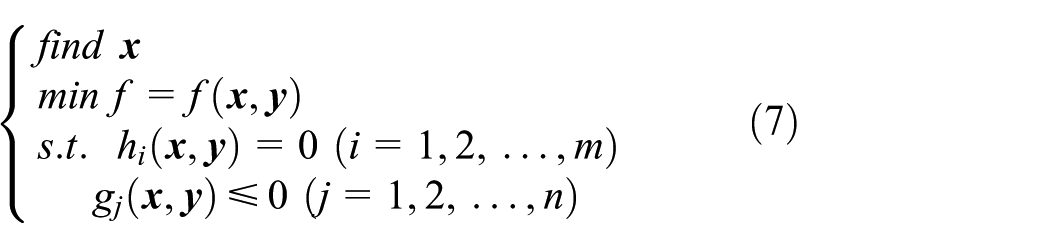
The principle of MDO can be given by
where
Many MDO architectures have been proposed in the literature. In this work, multidisciplinary feasible (MDF) and collaborative optimization (CO) are used to solve the problems of chain drive optimization. The MDF and CO computing framework are illustrated in Figure 2.
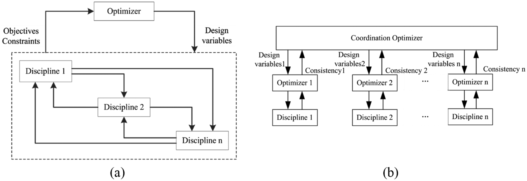
The MDF and CO computing framework. (a) The MDF framework and (b) the CO framework.
Sub-systems and restrictions
The structure of sub-systems
In the chain drive system, there are many parameters that affect chain drive performance, including the number of teeth in the small sprocket (z1), the chain pitch (t), and the number of chain links between the center distances (K0). In order to verify the influence of the above parameters on the chain drive system, the number of teeth of the small sprocket (z1), the chain pitch (t), and the number of chain links between the center distances (K0) are taken as the design variable. The matrix of the design variables can be given by

where x1 is the number of teeth in the small sprocket; x2 is the chain pitch, which is the continuous variable; and x3 is the number of chain links between the center distances, which is the integer variable.
The parameters of the chain drive system are listed in Table 1.
The parameters of the belt drive system.

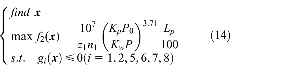
Chain transmission mechanism is usually composed of multi-row chain. To improve the transmission capacity of the chain drive system, this article selects the single row of the maximum transmission efficiency for the objective function. The structural subsystem can be given by

where


With the chain drive operation, the chain wear is increasing. The components of the chain drive system tend to be part of the fatigue limit of the parts. When the chain and sprocket are replaced, they need to be replaced at the same time. If the sprocket or sprocket is replaced individually by different wear degrees, it will be easier for the replacement parts to fail faster. Since the chain and sprocket are replaced, all chains and sprockets need to be replaced at the same time. If the chains or sprockets are replaced separately, the degree of wear between the parts is not the same so that all new components can be prematurely disabled. To reduce the cost of replacement parts, this article will maximize the fatigue life of the chain drive as an optimized objective function
where
The impact force of the chain drive system is one of the vibration sources of the whole system. In order to reduce the vibration, the impact force is set as one of the sub-disciplines. The optimization objective can be given by

Formulation of the constraints
As the number of sprockets teeth increases, the diameter and power of the sprocket increase with it. On the contrary, the polygonal effect of the chain is significant. Therefore, the number of sprocket teeth should be considered first. To reduce the power loss and the polygonal effect of the chain drive, this article sets the number of sprocket teeth as design variables. The number of sprockets must meet the basic requirements of a chain drive. The inequality is given by


In the chain drive, the greater the pitch, the greater the bearing capacity. However, the greater the chain pitch is, the more obvious the chain of polygon effect and vibration will be. Therefore, the chain pitch needs to be within a reasonable range to help the performance of the chain drive system to the best


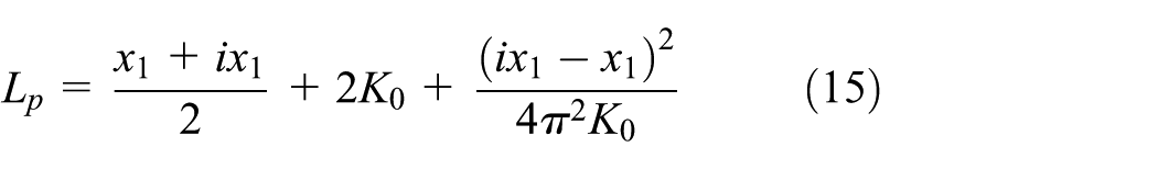
Chain drive can achieve long-distance transmission, to reduce the chain drive lateral vibration, the chain drive system not only needs to meet the system performance requirements, but the center distance should also be reduced as much as possible. The center-to-center distance is restrained as follows


where

In addition to the above advantages, there are still many shortcomings, such as: (a) work noise, (b) shock and vibration, and (c) high precision installation requirements. Normally, the power of the chain drive is proportional to the speed of the drive. To ensure that the speed of the chain drive can be within a reasonable range, the speed of the chain drive needs to meet the following constraint requirements


The maximum power of the chain drive should not be greater than the power required; therefore, the constraints of the continuous power are given by

Results
To balance global search and local search capabilities, this article selects the improved particle swarm optimization (PSO) algorithm. The PSO algorithm is the adjustment of the weight coefficient

where fmin is the minimum fitness value in population; favg is the average fitness value in population; f is the larger fitness value in two individuals to cross; wmin is the minimum weight coefficient value in population; and wmax is the maximum weight coefficient value in population.
The improved PSO is shown in Figure 3.

The flowchart of the improved PSO.
In order to obtain the optimal value of the parameters, this article uses PSO to compare the results of CO and MDF. In PSO, the number of population is set to 50, the learning factors are set to 2, and the maximum and minimum weight coefficient values are set to 0.9 and 0.6, respectively. The optimized results are shown in Table 2.
The optimization results.
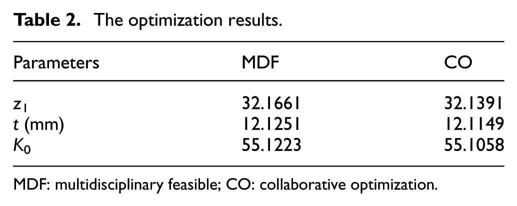
MDF: multidisciplinary feasible; CO: collaborative optimization.
As seen from the MDO results, the results of the CO are better than those of the MDF. The number of teeth obtained by using the PSO in the small sprocket obtained by CO is 32.1391, the chain pitch is 12.1149 mm, and the number of chain links is 55.1058, respectively. To evaluate the influence of CO method and MDF method on optimization results, this section compares the value of center distance, which is shown in Figure 4. It is interesting to note that the center distance of the CO method is less than the MDF method. From Figure 4, it is 76 mm less than the initial design. In the design variables, the number of teeth in the small sprocket and the number of chain links should be the integer variable. The designer should be rounded to the optimization results.
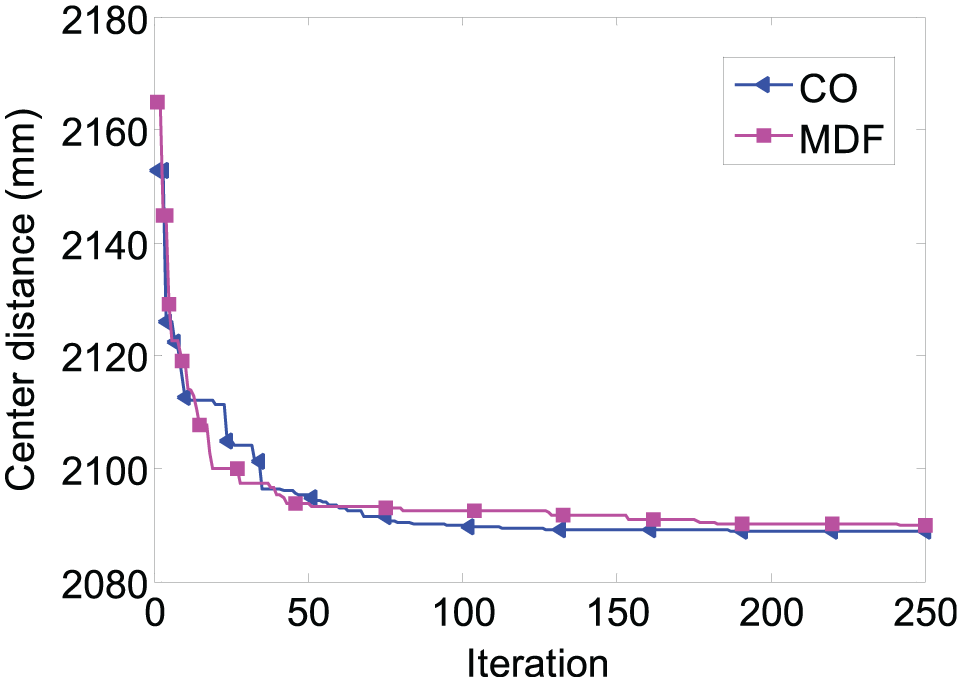
Comparison of convergence of CO and MDF.
Dynamic simulation of the chain belt drive
There are many methods established in the model of the chain drive system, including the FEA software, CAD software, and the ADAMS module. To obtain the accurate chain drive model, this article uses ADAMS module to establish the chain drive system in the virtual prototyping environment. This method not only guarantees the accuracy of the sprocket but also can easily modify the parameters. The chain drive system is shown in Figure 5.
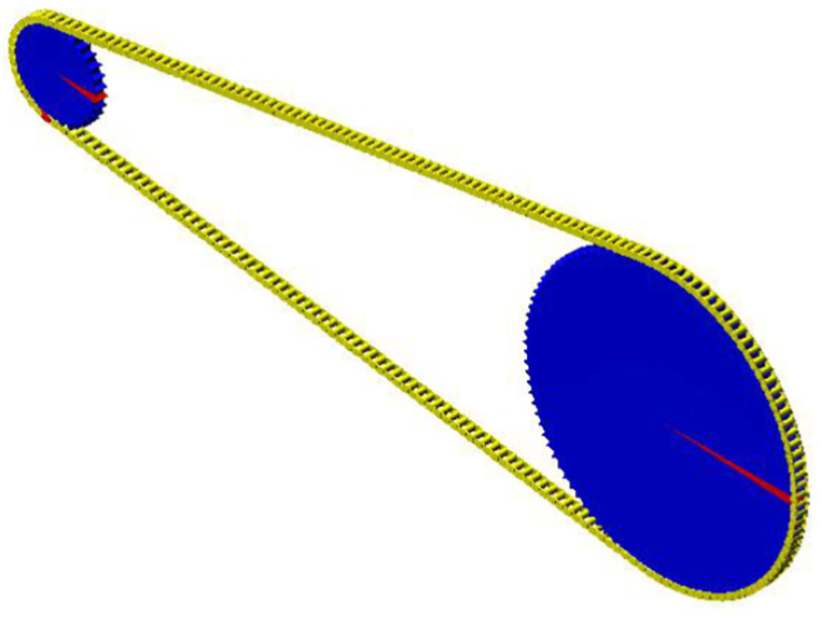
The chain drive system.
Results
The chain drive system was designed based on the results of the CO optimization. To study the transverse vibration characteristics of the chain drive, this study compares the effects of different velocities on the amplitude and frequency of transverse vibration. There are polygonal effects in the chain drive system. The main reason is that the transmission ratio of the chain drive is always changing in the transmission process. The transverse vibration of the different velocities of the chain drive is shown in Figure 6.

The influence of different speeds on chain drive system: (a) 900 r/min and (b) 1200 r/min.
Figure 6 shows that the amplitude of the transverse vibration increases as the speed increases. As shown in Figure 6(a), the vibration amplitude of the chain decreases with the increase in time. When the speed increases to 1200 r/min, the vibration is similar to that in Figure 6(a). By comparing Figure 6(a) and (b), the amplitude of chain drive system is increasing as the speed and the amplitude range of vibration is from −2 to 3 mm. To obtain the range of vibration frequencies of the chain drive system, the analysis in Figure 6 is carried out by fast Fourier transformation (FFT). The frequency curves are shown in Figure 7.

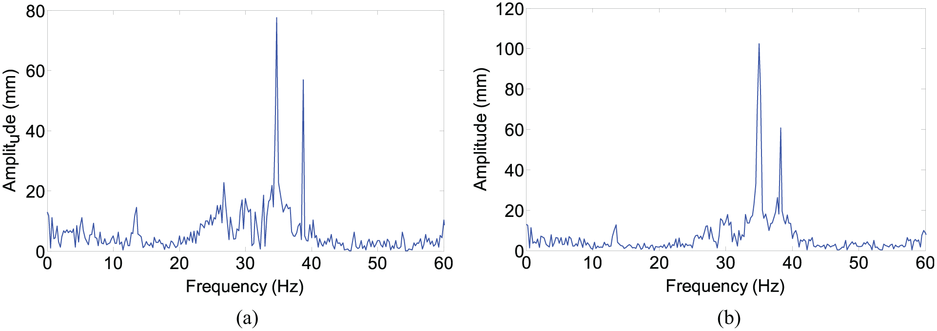
The influence of different velocities on vibration frequency: (a) 900 r/min and (b) 1200 r/min.
From Figure 7, it is seen that the amplitude of the vibration frequency increases as the speed increases. Figure 7(a) and (b) have many frequencies, including the natural vibration frequency and the multiplier of the chain drive. When the speed increases to 900 r/min, the main natural vibration frequency is 35.2 Hz and the amplitude of the vibration is 97.6 mm. The natural frequency of the chain drive system decreases as the speed increases. The maximum amplitude is 106.4 mm, which is similar to that in Figure 7(a).
Figure 8 illustrates that the speed fluctuation of the chain at 1200 r/min is obviously higher than 900 r/min. The vibration of the chain in Y direction is significantly higher than the vibration in X direction. In other words, the longitudinal vibration is smaller than the transverse vibration. The range of the transverse vibration is from −1000 to 1000 mm/s; however, the longitudinal vibration is only one-third of transverse vibration. To reduce the amplitude of the transverse vibration, designers can increase the shock absorber or tensioning wheel.

The influence of different speeds on the chain: (a) 900 r/min and (b) 1200 r/min.
Figure 9 shows the force between the adjacent chain links. The chain links are made of many chain links, so there is an elastic force in the transmission process. The force between the chain links changes little as the speed increases. It is seen that the force is between 110 and 190 N, and the force between the chain links changes little as the speed increases. To obtain the influence of different loads on the performance of the chain drive system, this article analyzes the transverse vibration, the vibration frequency, and the force between adjacent chain links at different loads under the same speed.

The influence of different speeds on the chain links: (a) 900 r/min and (b) 1200 r/min.
From Figure 10, it is seen that the amplitude of the transverse vibration increases as the load increases. When the load increases to 500 N, the range of the amplitude is changed from −3 to 3 mm. The amplitude range of the transverse vibration becomes larger than the low load. However, when the work is smooth, the amplitude of the transverse vibration is smaller than the low load. This article obtains the frequency curves by using the same method as above. The frequency curves are shown in Figure 11.

The influence of different loads on the chain drive system: (a) 300 N and (b) 500 N.
The influence of different loads on the vibration frequency: (a) 300 N and (b) 500 N.
Figure 11 shows the frequency curves at different loads. The amplitude of the vibration frequency increases as the load increases. By comparing Figures 7 and 11, it is seen that the amplitude of the vibration frequency in Figure 11 is obviously lower than that of in Figure 7. The main reason is that the energy consumption of the chain drive system increases as the load increases, resulting in a smaller force on the chain drive.
Figure 12 illustrates that the speed fluctuation of the chain at a 500-N load is obviously higher than 300 N load. As the load increases, the speed of the link increases first and then gradually becomes smooth. When the load is 300 N, the velocity of the chain link is between −600 and 600 mm/s in Y direction. However, the velocity in X direction is not obvious.

The influence of different loads on the chain: (a) 300 N and (b) 500 N.
Figure 13 shows the influence of different loads on the force between the chain links. By comparing Figure 13(a) and (b), it is seen that the force is smoother as the load increases. The maximum values of the force in Figure 13 are 192.5 and 231.3 N, respectively. The main reason is that the load starts to work and gets the maximum value in 0.1 s. To reduce the impact force in the process, the loading curve of the load should be given reasonably.

The influence of different loads on the chain links: (a) 300 N and (b) 500 N.
Future work
Chain transmission is one of the most common devices in mechanical transmission. This article uses the MDO method to solve the chain transmission, which can be used as a case study. In the future work, the improved PSO can be used to solve the real-world optimization problems. Moreover, the improved PSO also can be used in many fields, such as multi-objective optimization, minimum energy consumption optimization, and stability optimization. As the complexity of optimization problem increases, the PSO can be further improved.
Conclusion
In this article, an MDO method for chain drive system considering lateral vibration, vibration frequency, and optimal parameters is proposed. In the developed method, the chain drive system takes as a case to evaluate the performance of the new method. The mathematical model of the chain drive system and the transverse vibration analysis are carried out, respectively. To obtain the best performance for the chain, the result is executed by an improved PSO algorithm. Based on the results of MDO, the chain drive system is established and the dynamics simulation is carried out by virtual prototype technology. By analyzing the influence of different speeds and loads on lateral vibration, vibration frequency, and impact force of the chain links, this article has obtained the kinematics principle of chain drive and the optimal parameter value. The results show that the MDO method can obtain the optimal value of the structure size, and the optimal combination of the design parameters can be obtained. By comparison, it is interesting to note that the lateral vibration, vibration frequency, and optimal parameters can achieve the optimal solutions simultaneously. For example, the center distance is 76 mm less than the initial design. Taking the design of chain drive system as an example, this method is helpful for solving engineering optimization problems.
Footnotes
Appendix 1
Handling Editor: Michal Kuciej
Declaration of conflicting interests
The author(s) declared no potential conflicts of interest with respect to the research, authorship, and/or publication of this article.
Funding
The author(s) received no financial support for the research, authorship, and/or publication of this article.