
Abstract
Test as well as calibration precision of a coordinator is determined by the precision of the test turntable, and the improvement of the test turntable is the most effective way to improve the calibration accuracy of the coordinator. Therefore, it is of great practical significance and value to study a test calibration turntable which is suitable for a certain type of indexer. Based on the working principle of the ultrasonic motor, the mathematical model of the friction coupling interface is established; steady-state output force of the ultrasonic motor and the maximum angular velocity of the rotor are calculated; effect of the friction material type, magnitude of the pre-tightening force, and the rotor angular speed are analyzed on the maximum output force of the ultrasonic motor. The driving performance of the rotary table ultrasonic motor and the start/stop characteristic of the rotary table are studied. Finally, the driving ability of the ultrasonic motor is optimized and verified by experiments.
Introduction
With the continuous development and maturing of ultrasonic motor techniques, precision motion devices based on ultrasonic motors have been developed for use in calibration. 1 Ultrasonic motors are devoid of the traditional motor winding and magnetic circuit. They work based on the electrostrictive effect of piezoelectric materials, which is an inverse effect in which piezoelectric materials under a high-frequency high-voltage signal produce micro-mechanical vibrations in the ultrasonic frequency band. The vibration of the piezoelectric material is routed through the resonance amplifier and finally, the friction coupling dynamic linear motion or rotation is obtained. 2 Motion platforms based on ultrasonic motors are generally applicable to small load situations, and the precision of nano-level positioning and repeatability is achieved with the grating encoder. Typically, the dynamic performance is excellent. 3
Compared with ordinary electromagnetic motors, the ultrasonic motor has the advantages of high resolution, superior energy density, and frictional coupling direct drive, which endows it with a self-locking ability. Because of the piezoelectric-based driving mode, it has excellent electromagnetic compatibility, which shows the characteristics of low speed and high torque when driving the rotor.4,5 The concept of an ultrasonic motor was first proposed by Japanese scholar Sashida, 6 which was rapidly adopted by scientists in the United States, Germany, and Israel. Although China started in the field relatively late, it has made unremitting efforts to apply many of its research results to relevant areas such as industry and aerospace. 7
Based on the ultrasonic motor platform, motors can be divided into three types: a precision micro-motion platform, macro–micro precision platform combined with large stroke and direct drive, and large-stroke precision sport platform.8,9 In the case of the linear standing wave motor, there are more precise motion platforms for direct drive, such as the high-precision equipment developed by ALIO, which is used in precision optical instrument manufacturing, ultra-precision machining, semiconductor manufacturing, and high-precision automatic equipment. ALIO has developed a 6-DOF (degrees of freedom) parallel positioning platform, which has a wider working range and considerable structural rigidity. It is suitable for use in nano-processing and thermal bonding, has a fast response speed and high reliability, and can work in a vacuum environment. 10 The company Nano-motion has produced a series of high-performance ultrasonic motors, such as the HR2 ultrasonic linear motor drive of up to 7 N, and the HR4 ultrasonic motor drive up to 16 N. The three-dimensional platform positioning accuracy is 50 nm, and the platform has the advantages of no electromagnetic interference, superior dynamic performance, high accuracy, and simple structure.11,12
At present, test turntables with small load, high-precision positioning, and no external magnetic interference characteristics are not very common.13,14
In the light of research on “a comprehensive test system for a coordinator,” it is of practical value and significance to develop a special test turntable for a particular type of indexer. This study involves the design of a high-precision two-axis non-magnetic electric rotary table, examines the practical application of the standing wave ultrasonic motor, explores the influence of different operational factors on the driving force, and analyzes the positioning accuracy performance of the turntable. The results of this study are expected to form the theoretical basis for the design of high-precision rotary tables.
Experimental method for determining mechanical characteristics of two-axis turntable
Experimental setup
A schematic diagram of the two-axis turntable experimental device is shown in Figure 1. The two-axis precision turntable is composed of the mechanical frame, driving element, position detection element, controller, photoelectric switch, control handle, text display, and upper computer. The driving element is an ultrasonic motor.

Experimental device for two-axis turntable.
Selection of ultrasonic motors
The energy density of an ultrasonic motor is 5–10 times higher than that of an ordinary electromagnetic motor, and has the characteristics of low speed and large torque. It has a nanometer-level resolution and positioning accuracy, and high dynamic response with a response time of up to 5–10 ms. In addition, it has unlimited travel and a preload, which makes it self-locking.15–17 The driving mode of the ultrasonic motor is relatively simple and may involve direct driving contact with a cylindrical or plane drive surface, or a rotating shaft output motor that has evolved from the linear standing wave motor. 18 The structure of the ultrasonic motor is shown in Figure 2.

The structure type of Nano-motion ultrasonic motor: (a) The linear standing wave motor with single row contact points, (b) The linear standing wave motors with double rows contact points and (c) The linear standing wave motors with axis of rotation.
The linear standing wave motor shown in Figure 2(a) is suitable for cylindrical or plane driving surfaces and can be used in groups according to the required driving force. The linear standing wave motor shown in Figure 2(b) is suitable only for plane driving surfaces and is generally used in pairs. As shown in Figure 2(c), the ultrasonic motor converts the motion into a torque output type through friction coupling, which can engage directly with the rotating shaft.
The turntable designed in this study is a small load one with a load weight of 2 kg. A linear standing wave ultrasonic motor is selected as the driving element, which is suitable for the small load of the turntable and can attain high position resolution and repetitive positioning accuracy with ease. In order to reduce the cost and volume of the turntable, an HF2 type ultrasonic motor is selected in the case of the driving plane, with 4 numbers and 90° circumferential distribution.
Measurement of output force of ultrasonic motor drive
While installing ultrasonic motors, the pretension force is measured by using a push–pull dynamometer. It uses the preload value as the variable, measures the thrust force at the radius R of the gyrating part of the turntable, and obtains the motor preload and discrete relationship curve of the motor at steady output force.
For example, the mechanical characteristics of the rotary table are analyzed under a pre-tightening condition of 20–70 N. The input voltage of the drive is gradually increased from 0 to 10 V, and the output force and steady average speed of the azimuth axis are measured.
The position and speed of the azimuth axis are measured by the grating encoder; the grating is provided with a loose installation tolerance and the grating ruler is installed on the cylinder. The installation indicator on the head enables quick diagnosis; the grating has high anti-fouling ability so that dust, scratches, slight oil stains, and so on do not affect the measurement resolution. The resolution of the grating system is up to 1 nm and the grid spacing is high. The system is capable of withstanding harsh working environments with working temperatures as high as 80°C and the reading head sealing is good and matches IP64 standards. 12
Ultrasonic motor output force experiment and result analysis
The azimuth axis is driven by four sets of ultrasonic motors with 20, 30, 40, 50, 60, and 70 N pretension applied to each of the HF2 ultrasonic motors, and the output force of the azimuth shaft and the maximum steady-state speed are then measured.
Under the 20 N pre-tightening force, the dead zone voltage of the ultrasonic motor is approximately 0–3.0 V, maximum speed of azimuth shaft is approximately 39.26 °/s. The steady-state output force on a single HF2 type motor was gradually increased to a constant value around 3.59 N, azimuth shaft power self-locking force is 12.5 N, as shown in Table 1.
Mechanical properties of azimuth shaft (pretension: 20 N).

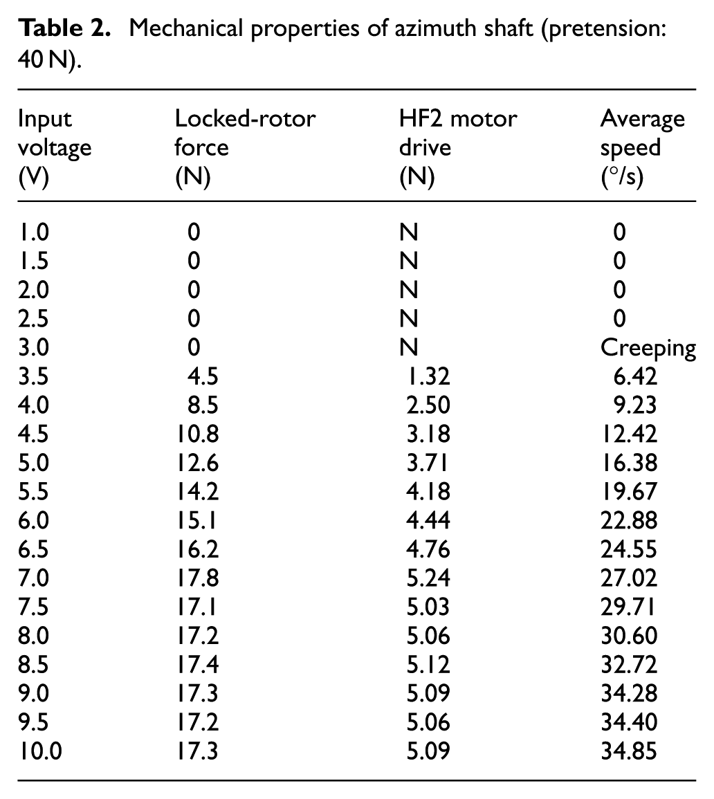
Under the 40 N preload, the dead zone voltage of the ultrasonic motor is 0–3 V. The maximum steady-state speed is 34.85 °/s, and the steady output power increases from 0 to a constant value of 5.09 N. The steady-state output forces corresponding to the input voltage of 7–10 V is basically identical. The de-power-off self-locking force of the azimuth shaft is 22.0 N, as recorded in Table 2.
Mechanical properties of azimuth shaft (pretension: 40 N).
The experimental data under different pre-tightening forces are recorded and analyzed to obtain the relationship between the driving force of the ultrasonic motor and the simulated voltage and preload. The result is shown in Figure 3.

Driving force and voltage relationship under different pretension forces in HF2.
The experimental results show that the maximum driving force of the ultrasonic motor is gradually increased with the increase in the pre-tightening force of the motor, while the maximum driving force has a constant value that lies in the range of 40–70 N, which is stable at about 5.2 N.
The maximum steady-state angular velocity related to the same input voltage of the driver is different under different preload conditions. By analyzing the experimental data, the azimuth velocity and input voltage relationship curve of different pre-tightening conditions are obtained, as showed in Figure 4.

Angular velocity and voltage relationship of the azimuth axis under different pretension forces.
It is shown by experiment that the high pre-tightening force of the motor, the lower the steady-state speed of the rotary table rotor at certain time of the analog voltage. When the pre-tightening force of the HF2 motor is 20 N, the maximum velocity of the rotor is 39.26 °/s. With the increase in pre-tightening force, the maximum angular velocity of the rotor decreases, and when the pre-tightening force is 70 N, the rotor angular velocity is 30.73 °/s, which is the largest obtained value.
The above analysis also concludes that for a pre-tightening force greater than or equal to 40 N, the maximum driving force of the HF2 type ultrasonic motor remains unchanged at 5.2 N, the maximum steady-state speed is 34.85 °/s, and the maximum steady-state velocity azimuth axis along with the increase of pre-tightening force decreases. Thus, a preload of 40 N may be considered the optimal value.
Ultrasonic motor output force analysis and simulation
Analysis of driving mechanism of linear standing wave ultrasonic motor
In theory, the stator drives the impact friction material with high-frequency elliptical motion and the friction material, in its turn, deforms elastically under the high-velocity impact of the stator. The friction material is equivalent to a linear spring uniformly distributed in series, with an equivalent spring rate k, while the stator drive foot end is considered as a rigid particle point. 19 The stator of the ultrasonic motor compresses the friction material with a certain pretension force and establishes a right-angle coordinate system with the major and minor axes of the stator elliptical trace, with the major axis in the direction of the neutral plane of rotation of the stator. 20 Owing to the preload, the neutral plane is inside the friction material, and the depth of the neutral surface is δ embedded into the friction material, as shown in Figure 5.

Equivalent friction coupling interface schematic diagram.
The stator contacts the friction material at point a, the friction material is driven from points a to b, and the stator is disconnected from the friction material interface at point b. The positions a and b, respectively, correspond to the angular positions φa and φb. That is, in a driving cycle, the rotor can contact the friction material only if 0 ≤ ωt ≤ φb || φa ≤ ωt ≤ 2π condition is satisfied, and the corresponding angle is defined as the contact angle φc. 12
In the case of intermittent contact between the motor drive foot and friction material, the bending vibration and normal longitudinal vibration displacement in the tangential direction of the foot end are, respectively

1. Calculation of equivalent stiffness of friction material
The friction material is modeled as a series of uniformly arranged linear springs having an equivalent stiffness k. A micro-segment of the friction material in the shape of a rectangular parallelepiped is considered, with the material section being identical to the single driving foot end face. The material has length a, width b, and height h, the applied external force is ΔF, and the resultant dimensional change in the direction of the applied force is indicated by Δh.
The elastic modulus Em of the friction material is obtained according to the elastic modulus formula

from which

Because the friction material is considered equivalent to a spring

Therefore, the equivalent stiffness between the driving foot and the friction material is given by

2. Calculate the normal force at the friction interface
From the equivalent stiffness k and preload F0, the depth of the friction material embedded in the neutral surface δ can be calculated as

According to the equation for the equivalent linear spring stiffness, the normal force at the friction interface is obtained as
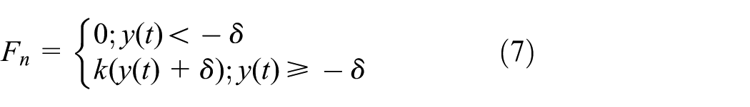
By substituting equations (1) and (6) in equation (7), the normal transient force Fn can be expressed as

The friction materials on the stator and rotor undergo high-frequency cyclic contact, and the stator tangential speed is sometimes the same as the rotor tangential speed. Thus, the materials appear to be bonded together. It can be cut at the speed of time and sometimes it is above or below the rotors, and Sliding friction is also observed, which is dependent on the relative speed, and this friction can be considered analogous to sticky friction; 21 friction coupled with the Fq can be expressed as
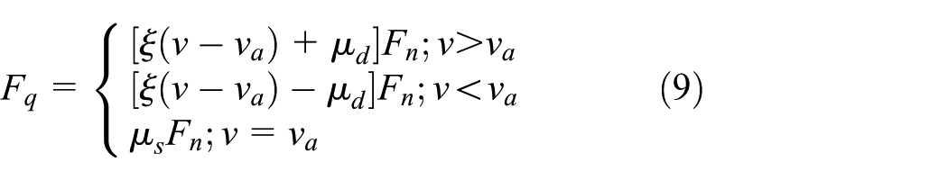
where the v is velocity which drives the tangential of the foot; νa is steady-state speed of rotor; μd is dynamic friction coefficient, μd = 0.1; μs is static friction coefficient, μs = 0.15; ξ is viscous friction coefficient, ξ = 0.05.
When the pre-stressing force F0 < kYm, that is, the contact angle is equal to π ≤ φc < 2π, there is only intermittent contact with the friction material. According to equation (9), the steady-state output force expression of the single drive foot of the ultrasonic motor can be obtained as
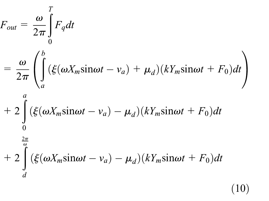
The friction materials generally used are alumina, alloy steel, and 7075. The stator tangential amplitude Xm is 1 μm and the normal amplitude Ym is 0.5 μm. The maximum angular velocity ω is equal to 3 × 10⁵ rad/s. The influence of the magnitude of the stator preload and the speed of the rotor on the output force of the driver is analyzed, and the variation of the stator driving force Fout with changes in F0 and va is plotted in Figure 6.
3. Calculation of the maximum steady-state velocity of azimuth axis

Relationship between the driving force–preload force–velocities of different friction materials.
When the rotor speed is constant, the positive and negative work done by the stator in one cycle are equal, at which time the system reaches steady-state equilibrium. Assuming that the average velocity of the azimuth axis is maximum steady-state value va at the instant being considered, the momentum is no longer changing, the rotor is subjected to zero force at that instant, the driving force of the pedal is equal to the driving force impulse of the rotors and the resistance momentum for a driving cycle, the specific relationship is given by
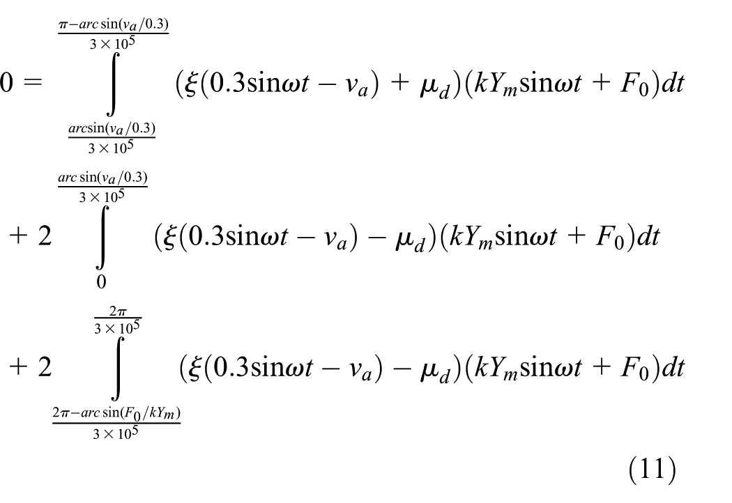
The friction materials used are, respectively, aluminum alloy, alloy steel, and 99% alumina. The relationship between the pretension force and maximum speed of the rotor is analyzed, known parameters of the ultrasonic motor are included in equation (11), and the relation curve between the pretension force and maximum steady-state velocity is obtained as shown in Figure 7.
4. Calculation of output torque of azimuth axis

Relationship between the pretension and the maximum steady-state velocity of various friction materials.
The axle is driven by a cylindrical surface after four HF2 motors are arranged symmetrically in groups, ignoring the friction force of the axle system. The cylindrical surface radius R = 119 mm. As the contact area between the motor driving foot and cylindrical surface is relatively small, the cylindrical surface is equivalent to a plane, and the azimuth axis moment is represented by

According to equation (12), the relationship curve between the torque of the azimuth axis and the angular speed and preload of the rotor is obtained as shown in Figure 8.

The curve among azimuth axis torque, preload, and angle velocity.
When the preload force of 90 N, which indicates a preload force of 45 N per driving foot, is applied to the HF2 ultrasonic motor, the output torque of the azimuth axis is the largest at Mout = 4.44 N m.
Simulation of ultrasonic motor drive performance
For the connecting rod of the ultrasonic motor, the eccentricity E is the amplitude of the guide shaft of the ultrasonic motor, and the amplitude of the short shaft of the ultrasonic motor is changed by the proportional motion of L1 and L2. The eccentric wheel, connecting rod, and rotary sliding pair are fixed on a frame whose left end is connected to a pretension spring with a rigidity of K and an initial preload force F0. High-frequency collisions occur between the end of the connecting rod and the alumina ring. The driving performance of the ultrasonic motor is analyzed through ADAMS modeling simulation.
According to the typical parameter values of the ultrasonic motor, an equivalent mechanism of eccentricity e = 0.001 mm, imposed on an active rotation speed of n = 47,500 rad/s, is equivalent to a connecting rod end frequency of 47.5 kHz, with a 2-micron long axis for elliptical motion, as shown in Figure 9.
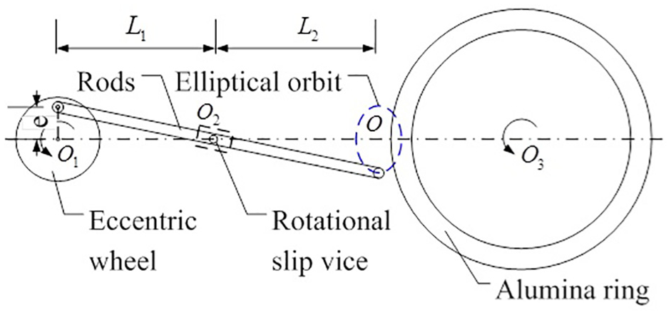
Equivalent model and simulation diagram.
The pretension spring stiffness is set as k1 = 15,000 N/m for the ultrasonic motor, and to apply different pre-tightening forces to the motor stator, the preload of the spring is set to F = 30, F = 50, and F = 70 N successively and the output torque and angular speed of the rotor are determined. The result is shown in Figure 10.

Relation curve of rotor torque and pretension force.
It is indicated that the maximum output torque of the rotor can be increased by increasing the pre-tightening force; when the pre-tightening force F is 30 N, the torque applied to the rotor is 0.24 N m and the equivalent electric motor thrust 2 N. When the pre-tightening force is 50 N, the torque applied to the rotor is 0.33 N m and the equivalent motor thrust is 2.8 N. When the pre-tightening force is 70 N, the torque applied to the rotor is 0.51 N m and the equivalent motor thrust is 4.25 N.
The variation of angular velocity parameters with different pretensions are shown in Figure 11.

Pretension—rotor torque and speed relationship.
The results show that with the increase of pre-stressing force, the steady-state velocity of rotor decreased. For a single drive foot when the pre-tightening force F is 30 N, the maximum rate of steady rotor is 56 °/s; when the pre-tightening force is 60 N, the maximum rate of steady rotor is 45 °/s; when the pre-tightening force F is 100 N, the maximum rate of steady rotor is 23 °/s.
The drive form of the ultrasonic motor indicates a strong driving force and speed non-linearity, 15 which confirmed by analyzing the rotor, and the result is shown in Figure 12.

Transient driving force of micro-collision.
The motion of the rotor exhibits strongly nonlinear behavior, and there are rapid changes in the driving force in small intervals. This phenomenon occurs because the ultrasonic motor has a fixed frequency collision with the rotors, and the spike of the friction interface has to be at a peak of 2800 N.
Through the simulation, it is determined that the pretension force of the motor has an impact on the determinant drive and it determines the effect of the pre-tightening force on the rotor. Thus, it is verified that the ultrasonic motor drive of the rotor is very nonlinear.
Overall scheme design of two-axis precisionnon-magnetic rotary table
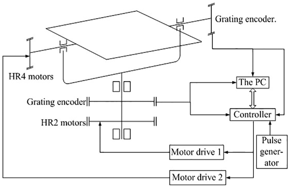
The two-axis precision rotary table is designed according to the specific working environment and related design requirements of the turntable. The two-axis precision rotary table is mainly composed of the mechanical structure body, horizontal rotation of the group and the pitch oscillation ultrasonic motor, grating encoder of two DOFs, motor driver, controller, PC, and so on. The composition of the two-axis precision rotary table system is shown in Figure 13.

Finite element mesh generation of the bottom plate.
The azimuth rotating shaft has ceramic bearings, which are made of alumina rings and 3M acrylic adhesives. The alumina ring is bonded on the rotary support, which is the friction coupling driving unit of HF2 ultrasonic motor. HF2 type ultrasonic motor can be adjusted before and after installation, which can change the pre-stress of friction. The rotary friction ring is made of 7075 aluminum alloy. After surface oxidation treatment, it has the advantages of corrosion resistance and oxidation resistance, ensuring good service life.
The adjustable grating ruler is installed on the grating plate, and the azimuth axis grating reading head is installed on the adjustable bracket to meet the mounting accuracy of the grating head. The design of the azimuth axis is shown in Figure 14.

Integral force displacement cloud chart of the bottom plate.
The pitch axis is driven by two right and left symmetrical HF4 ultrasonic motors, and the motor is convenient for installation and removal. The ultrasonic motor provides the alumina sheet with a certain pretension force, where the direction of this pretension is the non-sensitive direction of the pitching precision, and the mutual offset does not increase the frictional resistance. The pitching part has the advantages of small friction torque, stable motion, and high swing precision.
Finite element analysis of the strength of the two-axis turntable
1. Finite element analysis of the strength of turntable bottom plate
First of all, the overall structure is simplified, because the force of the bottom plate is the largest. So the strength of the bottom plate is analyzed. After gridding the bottom plate, 6.0 kg of dead weight is applied as shown in Figure 15. Figure 16 is the overall deformation cloud of the bottom plate.

Finite element mesh processing of upper swing rotor.

Force and stress cloud diagram of up rotating body.
According to the figure, the maximum deformation of the floor is 0.089975 mm and is located in the middle. This deformation characteristic shows that it will hardly affect the horizontal rotational motion.
2. Finite element analysis of swing rotor strength
By analyzing the structure of the pendulum rotor, it can be concluded that the copper slider and PTFE (polytetrafluoroethylene) adjusting block of the pendulum not only bear the weight of the entire upper pendulum but also bear the pre-tightening force of the ceramic motor about 35 N. The results show that the upper swing rotor is simplified after grid processing, as shown in Figure 17.
Two-axis turntable system composition.
The total load of the upper swing rotor is 1.7 kg. The maximum load of the T-groove is 0.7 kg, in which the combined force of slider and PTFE support is downward and 25 N in size. After applying the force, the lower surface is chosen as the fixed surface. The analysis results show that there is a maximum stress concentration at the upper swing joint with the maximum stress being 5.13 MPa. The results are shown in Figure 18. The selected material is aluminum alloy 1060 with a yield strength of 27.574 MPa, indicating that the structural strength of the upper swing design is sufficient.

Azimuth axis structure plan of two-axis turntable.
Motion experiments on turntable prototype of two-axis non-magnetic field
Turntable prototype of two-axis non-magnetic field
A two-axis precision non-magnetic turntable prototype based on an ultrasonic motor was developed on the basis of the previous analysis and simulation, which can realize a horizontal rotation range of ±170° and pitching direction of ±30°. The accuracy meets the index requirements. The table is used to place a marker, such as a seeker in a missile. The advantage of this turntable is that it is non-magnetic and can avoid interference from various external magnetic fields. The turntable prototype is shown in Figure 19.

Two-axis non-magnetic electric turntable and its control system.
Motion test experiments on two-axis non-magnetic turntable prototype
1. Testing of non-magnetic characteristics during rotary table motion
The high-precision magnetic field sensor JY-901 is used, and its 12-bit ADC and low-interference AMR sensor can achieve 5 mG resolution in a magnetic field of ±8 G. The sensor is fixed on the T-shaped groove table of the two-axis precision turntable, and the magnetic field strength at the center of the table is measured.
The magnetic field strength of the T-slot table is recorded in Table 3, and the two-axis precision turret is moved to other positions to measure the strength of the geomagnetic field at the same spatial position. By verifying the magnetic field strength, it was found that the strength of the magnetic field of the table is almost equal to the strength of the geomagnetic field. That is, the non-magnetic turret does not introduce a magnetic field nor does it cause distortion of the geomagnetic field.
Magnetic field strength measurement of two-axis non-magnetic turntable.

The positioner was mounted on a two-axis non-magnetic turntable for testing, and it was found that there was almost no interference signal in the positioner, as shown in Figure 20. The result shows that the non-magnetic design of the two-axis precision non-magnetic turntable conforms to the parameter test and calibration of the non-magnetic environment of the positioner.
2. Experiments on turntable start and corner positioning accuracy
(a) Analysis of azimuth axis starting characteristics

Magnetic field test during rotary table motion.
The controller sends a 1′ angle command to the azimuth axis to analyze the transient response performance of the turntable. The oscilloscope displays the response curve of the turntable, as shown in Figure 21.

Azimuth axis response curve.
At the moment of issuing the command, the acceleration of the turntable rises to the maximum, which is 1146 °/s2 and the response time of the azimuth axis is 6 ms. There is an overshoot phenomenon with the overshoot being 100%, but it is fast and stabilizes in 32 ms, and there is no steady-state error. It can be showed that the ultrasonic motor has high responsiveness and good positioning ability. The overshoot does not affect the stability of the system and can be quickly adjusted to the target position.
(b) Accuracy analysis of azimuth axis positioning
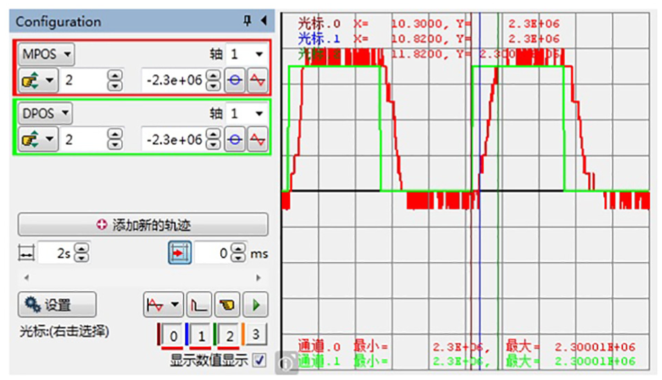
The controller sends a command to rotate the azimuth axis by 0.01′, it then analyzes the transient response performance of the turntable and displays the response curve of the turntable through an oscilloscope, as shown in Figure 22.

Positioning capability of the azimuth axis in STEP mode (preload force 40 N).
It can be concluded from Figure 16 that the azimuth axis has good positioning accuracy, the steady-state error is 0.0015′, the adjustment time is up to 2 s with the shortest being 0.5 s, with time-varying. There is an accidental overshoot in the adjustment process, and the overshoot is up to 300%, but it can quickly return to the vicinity of the target position. The reason for this phenomenon is the interference of external vibration. The high precision of the turntable makes the vibration of the desktop extremely small. This can cause overshoot of the azimuth axis control system, and these problems cannot be eliminated by adjusting the control parameters.
(c) Analysis of positioning accuracy of pitch axis
The pitch axis is controlled to reciprocate in the range of 0.01′, and the response curve of the pitch axis of the turret is displayed by an oscilloscope, as shown in Figure 23.
Positioning ability of the pitch axis in STEP mode (preload force 40 N).
It can be concluded from Figure 23 that the pitch axis has good positioning accuracy, steady-state error is 0.0012′, adjustment time is 1.5 s, and time variation is weaker than the azimuth axis. There is no overshoot in the adjustment process, there is no external interference, and the operation effect is stable.
Conclusion
This study examines the mechanical properties of a turntable, based on the working principle of an ultrasonic motor, a mathematical model of the friction coupling interface, the calculation of steady-state output force and rotor angular velocity, the analysis of the friction material type, size of pre-stressing force, the rotor angular velocity, and so on. For maximum output power of the ultrasonic motor, finally it is concluded that the optimum choice is alumina for friction materials, pre-tightening force is 45 N, and the largest single drive foot maximum output force is 3.2 N.
According to the analysis, the maximum operating angular velocity of the turntable is inversely proportional to the pre-tightening force, but the increase in the pre-tightening force can reduce the startup time of the turntable. Finally, the relationship between the magnitude of the pretension force and output force of the ultrasonic motor as well as maximum angular velocity of the rotor is verified through the simulation analysis, and it is identified that the driving form of the ultrasonic motor is very nonlinear.
Footnotes
Handling Editor: António Mendes Lopes
Declaration of conflicting interests
The author(s) declared no potential conflicts of interest with respect to the research, authorship, and/or publication of this article.
Funding
The author(s) disclosed receipt of the following financial support for the research, authorship, and/or publication of this article: This paper is funded by NSFC (Contract name: Research on ultimate bearing capacity and parametric design for the grouted clamps strengthening the partial damaged structure of jacket pipes). (Contract name: 51879063) (Contract name: Research of Analysis and Experiments of Gripping and Bearing Mechanism for Large-scale Holding and Lifting Tools on Ocean Foundation Piles), (Contract number: 51479043). And the views expressed here are the authors alone.