
Abstract
A circuit breaking electromagnetic system is the actuator and digital controller for a switching device. Its performance can significantly affect operations of the switching device. We propose a dynamic simulation method coupling the electric field and the magnetic field for the circuit breaking electromagnetic system and its drive circuit. The method combines both statistic and dynamic analyses, and differential equations. Finally, we utilize the flux transformer as an example to validate this method and reveal the dynamic characteristics of the drive transformer by changing the parameters of the drive circuit.
Introduction
An electrical circuit breaking device is often composed of a sensing and an executing part, and the connection between them depends on an electromagnetic system which receives signals from the processor and drives the mechanical part to work. The electromagnetic system serves as a critical hub for electrical circuit breaking appliances, and its performance can directly affect the function of the switch device, as well as its economic and technical aspects. Therefore, it is of great value to study dynamic simulation of electromagnetic systems.
Electromagnetic systems for circuit breaking devices1–4 and the electromagnetic finite element simulation for certain integrated circuits5–8 have been extensively investigated. Li et al. 9 proposed a methodology for optimization, while in our study, optimization mainly involves a static analysis, a dynamic analysis, and an algorithm. We investigate the MITOP ECO circuit breaker tester, a new type of electromagnetic system, whose function is to release the energy stored in a spring. The methodology is used to minimize the price of the device and reduce the onload opening time. Wang et al. 10 utilized calculation result of the static characteristic to illustrate the influence of current direction on electromagnetic force when it acting on magnetic release. Ladas et al. 11 discussed a specific problem in finite element analysis, meshing. They designed an energy-based error criterion for adaptive meshing and applied it to the eddy current problems; thus, remeshing of conductors could adapt discretization to the skin effect. Conventional simulations usually used finite element method (FEM) to analyze contactor motion because analysis of accurate magnetic force and distribution of magnetic flux are the core issue, while Wada et al. 12 applied the FEM to the electromagnetic system and the entire contactor was modeled by differential equations that were solved by the Runge–Kutta method for rapid calculation. Ramirez-Laboreo et al. 4 established a new multi-field coupling and nonlinear electromechanical relay model and investigated dynamic characteristics of electromagnetic relay by combining the electromagnetic model and the mechanical model. Zhai et al. 13 developed an electromagnetic relay model by coupling structure finite element calculation, electromagnetic finite element calculation, and dynamic numerical calculation. They used the model to calculate the angle and current characteristics of relay release and analyzed the electromagnetic, dynamic and functional characteristics of the relay during pull-in and release stages. Shu et al. 14 used the FEM and partial differential equation combination method to simulate the electromagnetic response of the alternating current (AC) electromagnetic contactor system. They also deployed the numerical interpolation method to calculate the transient and static characteristics of electromagnetic field in order to analyze the nonlinear response of magnetic field and magnetic force.
Much work on electromagnetic system for circuit breaking devices so far has focused on static simulation, as well as the influence of the coupling of electromagnetic field and mechanical field on circuit breaking and electromagnetic characteristics, while relatively few studies have devoted to the influence of the drive circuit on the dynamic parameters of electromagnetic system for circuit breaking devices.
Therefore, we propose a dynamic simulation method by coupling electric field and magnetic field for the circuit breaking electromagnetic system and its drive circuit which can be observed as the static characteristics in different working situations. Then, we simulate the static characteristic by utilizing finite element analysis while calculating the dynamic characteristic in MATLAB based on the Runge–Kutta algorithm. Finally, we take the magnetic flux converter as an example to validate the simulation method, especially the dynamic influence of the drive circuit on the electromagnetic characteristics.
Dynamic simulation method
A typical electromagnetic breaking system consists of three parts: the moving executive part, the electromagnetic part, and the drive circuit part. The electromagnetic part can generate a magnetic field. When the magnetic field grows large enough, the moving executive part starts to move. The driving circuit generates a current during capacitor discharge, which enables the electromagnetic system to obtain the magnetic field. The principle of the circuit breaking electromagnetic system is shown in Figure 1. A mathematical model for the electromagnetic system will be complex since the circuit breaking contains different phases. Therefore, we present a method of static and dynamic simulation for effective description.

Principle of the circuit breaking electromagnetic system.
The static simulation is performed before the dynamic analysis. The static simulation of the circuit breaking electromagnetic system is based on a physical model and the finite element analysis. It analyzes the time history for the entire movement of the plunger and disperses the entire time period into a number of static time points. Thus, magnetic field distribution, flux and electromagnetic forces under different conditions can be determined at each discrete point. The air gap and the circuit current are also provided at each point.
The static analysis can obtain not only the intensity distribution map of the magnetic field, but also the two-dimensional data tables for the magnetic flux
Traditionally, solving dynamic motion equations of the circuit breaking electromagnetic system by a rigorous analytical method is impossible due to its complexity. Thanks to the rapid development of IT technology, the equations now can be effectively be calculated with improved accuracy, and the relationship between current, electromagnetic force, air gap, and velocity with time can therefore be easily determined.
In this article, we utilize the Runge–Kutta method to solve the differential equations of the dynamic characteristics of the circuit breaking electromagnetic system. The Runge–Kutta method is a precise general numerical method for differential equations and has been extensively used in system simulation. Its truncation error is proportional to h 5 , and its programming is easy and the calculation process is stable. Moreover, the step length can be easily adjusted. Therefore, the Runge–Kutta method is a reasonable choice for our study.
The process of dynamic simulation is shown in Figure 2. First, a mathematical model is established. Then, time period is dispersed. Third, solutions of the differential equations, as well as the dynamic characteristics of the circuit breaking electromagnetic system, are determined by the Runge–Kutta algorithm.
Flowchart of the dynamic simulation.
Instantiation: flux transfer trip
We take a flux transfer trip as an example to validate our dynamic simulation method.
Modeling
The structure of the flux transfer trip is shown in Figure 3. Electricity was provided by a capacitor. The structure of the flux transfer trip and its drive circuit are shown in Figure 4.
The flux transfer trip.
Working principle of the flux transfer trip and its drive circuit.
When the current goes through, flux from the coil will be generated and weaken the flux from the permanent magnet. As such, the electromagnetic force Fm decreases. During discharge process, current I increases, and so does Fm. When Fm is greater than the spring force, the moving core will start to break away from the permanent magnet and pushes the mechanical part of the switch device. When the circuit functions normally, the plunger will stay energized with the permanent magnet inside. When the circuit malfunctions, a current transformer connected to the circuit will detect the fault and the dashboard will provide a direct 12 V current power to the coil of the flux transfer trip. When the circuit current reaches a certain value, the electromagnetic force of the plunger provided by the circuit current and permanent magnet will be less than the force from the spring. When the plunger starts to release and conduct a tripping action, the operating mechanism will be induced to act. Therefore, the entire action process of flux transfer trip can be divided into two phases. In Stage 1, spring force is defined as Ff. With the gradual increase of the discharge current from the capacitor, the magnetic flux generated by the permanent magnet gradually weakens. As such, the electromagnetic force Fm on the plunger gradually decreases. If Fm > Ff, the plunger stays still. Stage 1 lasts t1 seconds. Coupling coil circuit equations are used to obtain the following dynamic equations

where U is the drive voltage, V; C is the capacitor, µF; R is the circuit resistance, Ω; i is the circuit current, A; Fm is the composition of the forces from the permanent magnet and the coil on the plunger, N;
Stage 2 is the motion stage. In this stage, Fm < Ff. The plunger starts to move from the permanent magnet. The following dynamic equations can be derived based on the circuit equations and Newtonian mechanics of the plunger

where
Static simulation
First, a virtual prototype model of the flux transfer trip is established on the ANSYS platform. The parameters, mesh, coil, and boundary conditions are set. As a result, the electromagnetic force and flux can be determined based on a group of air gaps and current values. The model of the flux transfer trip and the intensity distribution map of the magnetic field are shown in Figure 5. The result of the static simulation is shown in Tables 1 and 2.
(a) Model of flux transfer trip and (b) intensity distribution map of magnetic field.
Results of the electromagnetic force Fm under different values of I and x.

Results of the flux of the coil Ψ under different values of I and x.

The relationship between the electromagnetic force and the circuit current and that between the electromagnetic force and the air gap can be depicted based on the simulation data previously presented (Figure 6).

Relationships between electromagnetic force and circuit current as well as air gap: (a) electromagnetic force for different circuit currents and (b) electromagnetic force for different air gaps.
Evidently, whenever one of the two parameters, I and x, is constant, the electromagnetic force holds a regular relationship with the other parameter. For a certain value of air gap x, a larger current indicates a smaller electromagnetic force, which is similar to the relationship between the electromagnetic force and the air gap when the current is constant. The change of the electromagnetic force for different currents is relatively smoother.
Dynamic simulation
Dynamic simulation analysis in MATLAB focuses on the dynamic process of the flux transfer trip. As discussed before, the electromagnetic force Fm is related to the air gap and the coil current and their relationships are nonlinear. The current is from the discharge process of a charged capacitor. It changes nonlinearly with the discharge process and is determined by the voltage U and the capacitor C. The size of the air gap and the magnitude of the spring force entirely depend on the movement of the plunger.
As shown in Figure 7, the plunger trips rapidly. The displacement of the movement is 8 mm and the entire action lasted less than 6 ms.

The dynamic characteristics of flux transfer trip.
The minus sign of the value of the electromagnetic force denotes the downward direction of the combined forces from the permanent magnets and coils on the plunger. As shown in Figure 7, electromagnetic force and spring force demonstrate that Fm starts to decrease from approximately 2.7 to 0N throughout the entire action of approximately 2 ms. At this specific point, the distance between the plunger and the permanent magnet is sufficiently large. The current is also reduced and the effects of both sides are almost offset. In the following process, the force that pushes the plunger is mainly from the spring. By contrast, in the moving process, the force from the spring also continues to decrease. The force from the spring first reaches the maximum of 4.8 N when the spring is not in motion. With the plunger moving away from the permanent magnets, the amount of compression of the spring is constantly decreasing. When the tripping process stops, the spring has been completely released and stays in a relaxed state. In brief, in the entire course of the tripping process, the combined effects of the electromagnetic force and the spring push the plunger to move.
As shown in Figure 7, the current in the coil is from a charged capacitor during the discharge process. As such, theoretically, the change of the current is in accordance with the equation
As we can seen from the relationship between velocity and displacement in Figure 7, when the plunger accelerates and moves away from the permanent magnet under the effect of the electromagnetic force and the spring force illustrates that the velocity of the plunger increases from zero and reaches the maximum of 2.7 m/s at the moment when the action is over. The entire process is not linear. Acceleration first increases and then decreases, which is the result of the changes and the effects of electromagnetic force and the spring force at the same time.
Influence of drive circuit parameters
Introduction of drive circuit of the flux transfer trip
As shown in Figure 8, the drive circuit receives the signal (high = 5 V/3.3 V, low = 0 V) from the microprocessor and charges or discharges the capacitor to control the flux transfer trip. It is required to have anti-jamming properties, high circuit stability, high action reliability, and rapid action. The flux transfer trip should neither take a long time to power nor occupy microcontroller unit (MCU) resources alone. Moreover, the control method should be easy.
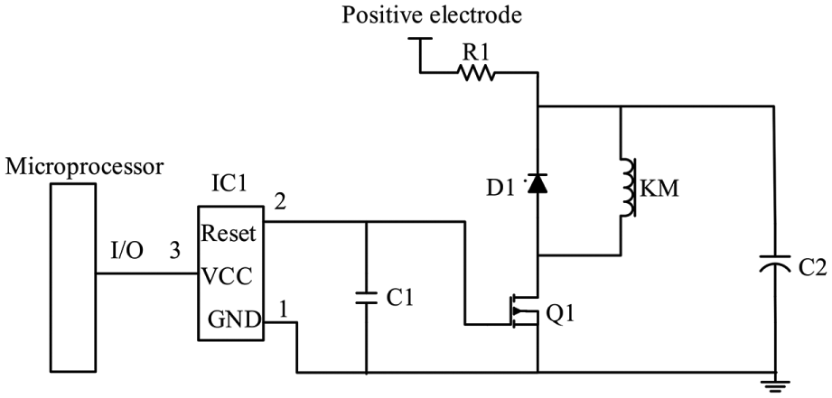
Drive circuit of the flux transfer trip.
The drive circuit of flux transfer trip is usually achieved by electrical relays, which leads to high cost, and high chances of malfunctioning. A reliable and malfunction-resistant drive circuit for flux transfer trip is significant for the reliable operation of low-voltage electrical appliances.
Three factors in the driving circuit of flux transfer trip, circuit resistance, supply voltage, and capacitance, can influence the final dynamic characteristics. Controlling and changing the values of the three parameters can obtain different simulation results. Apparently, these results and conclusions will be of reference values for the optimization of flux transfer trip, especially of the drive circuit part.
Influence of the change of resistance on the dynamic characteristics
Setting U = 12 V and C = 2200 µF and adjusting the resistance, the simulation results are obtained and shown in Figure 9.

The influence of the change of resistance on the dynamic characteristics.
The following conclusions are drawn from Figure 9:
The larger the resistance, the smaller the initial current, thus the larger the electromagnetic force.
The smaller the resistance, the larger the ultimate velocity. Resistance values between 1.5 and 2 Ω barely make any difference to the final velocity. However, resistance values greater than 2 Ω can be influential.
The smaller the resistance, the shorter the time for completing the action. When R > 2.8 Ω, the plunger is unable to trip.
In summary, when the charging voltage and the capacity of the capacitor remain unchanged, the resistance should be controlled at 2 Ω ± (0.5 Ω) while in the range of 2.5–2.8 Ω, the plunger can still trip. However, the kinetic energy is small and the subsequent influence is slight. When resistance is greater than 2.8 Ω, the plunger is unable to eject.
Influence of the change of capacitance on the dynamic characteristics
Setting U = 12 V and R = 2 Ω and adjusting the capacitance, the simulation results are obtained and shown in Figure 10.

Influence of the change of capacitance on the dynamic characteristics.
The following conclusions are drawn from Figure 10:
When the capacitance is less than 470 µF, flux transfer trip will not trip.
The smaller the capacitance, the smaller the final velocity of the plunger.
The smaller the capacitance, the shorter the circuit discharge time.
The smaller the capacitance, the longer the time for completing the entire course of action.
In summary, when the charging voltage and the circuit resistance remain unchanged, it barely makes any difference to the trip time whether the capacitance is 1000 or 2200 µF. The tripping action is completed in 2 ms. A capacitance of 470 µF is the limit for the flux transfer trip to trip. At a capacitance of less than 470 µF, the flux transfer trip is unable trip.
Influence of the change of voltage on the dynamic characteristics
Setting C = 2200 µF and R = 2 Ω and adjusting the voltage, the simulation results are obtained and shown in Figure 11.

The influence of the change of voltage on the dynamic characteristics.
Analyzing the graphs shown in Figure 11, the following conclusions are drawn from Figure 11:
The larger the voltage, the larger the starting current, and the smaller the electromagnetic force.
The larger the voltage, the larger the final velocity. However, the voltage only has a slight effect on the velocity.
The larger the voltage, the shorter the time for completing the action. When U < 8.4 V, the plunger is unable to eject.
In summary, when the capacitance and the circuit resistance remain unchanged, the higher the initial capacitor voltage, the shorter the trip time, and the larger the velocity after ejection. When the voltage is in the range of 12–15 V, the final velocity is more or less the same. Therefore, the initial voltage on the capacitor should be improved in the case of strict time constrains and the initial voltage of the capacitor can be selected appropriately based on the actual situation in case of strict requirements for final kinetic energy.
Conclusion
In this article, we propose a dynamic simulation method for electromagnetic system combined with drive circuit and verify it by being applying it to a flux transfer trip. The circuit breaking process of the electromagnetic system is a complex dynamic process. In this study, we analyze the performance evaluations during the tripping action, as well as the dynamic characteristics of flux transfer trip, and present the results in graphs.
We develop a static simulation using the finite element analysis method in ANSYS. As a result, the relationship between the magnetic force and the current and that between the magnetic force and the air gap are determined. The dynamic simulation, which is achieved by the fourth-order Runge–Kutta algorithm in MATLAB, is based on the static characteristics data at different working conditions.
The parameters of the drive circuit can greatly influence the dynamic parameters of the electromagnetic system. It is easy to optimize the electromagnetic system by changing the factors of resistance, capacitance, and inductance of the drive circuit.
Footnotes
Acknowledgements
The authors are grateful for the reviewers of initial drafts for their helpful comments and suggestions.
Handling Editor: Alexander Hosovsky
Declaration of conflicting interests
The author(s) declared no potential conflicts of interest with respect to the research, authorship, and/or publication of this article.
Funding
The author(s) disclosed receipt of the following financial support for the research, authorship, and/or publication of this article: This research is supported by the National Key R&D Program of China (2016YFB1200402) and the National Natural Science Foundation of China (61703308).