
Abstract
This rotary engine comprises a cylindrical chamber inside a casing wherein there is a concentric rotatable power shaft and a rotatable asymmetric main wheel mounted eccentrically enough as such to avoid contact with the wall of cylindrical chamber. In addition, two bars traversing the main wheel radially further have a wiping contact with the cylindrical chamber wherein one bar is fixed with power shaft and other bar is hinged with said power shaft. A combustion process is in detonation phase within a demarcated combustion chamber whereby the combustion chamber rotatably travels from a bottom dead volume to a top dead volume, and hence, a power, generated during this path of rotational travel, is subsequently available for delivery at the concentric power shaft.
Keywords
Introduction
A rotary engine is widely known for its feature that does not change direction of momentum during its rotation. This type of phenomenon thus clearly grants an advantage to the rotary engine over the existing piston/reciprocating engine where periodic momentum change repeatedly causes an enormous stress and erosion in metal structure of a piston engine which can significantly degrade an overall engine performance after extended period of service. However, a well-built rotary engine also creates stress on engine parts, but in the case of momentum change, its degree of performance degradation over time is not as high as that of piston engine. The traditional rotary engine (known as Wankel engine) which might not have a high stress issue during rotation as rotary piston does not angle speed variation at constant speed, but it has another issue, such as, its Epitrochoid profiled structure of combustion chamber creates frequent sealing problem due to its unsymmetrical contact of combustion chamber with Apex seals and further having relatively low crank radius that results in low fuel efficiency as torque is the function of force and radius. Beside the Wankel engine, a recently invented rotary engine like “Liquid piston technology” can be named accordingly which has a main rotor only and no valve. However, while considering the working principle, one can reach a conclusion that this “Liquid piston technology” is considered equivalent to an engine system where three piston-cylinders can be arranged in a circular way and the rotor pushes the centrally rotating crankshaft to rotate. This kind of action of rotor makes an inclined projection of impact on an eccentric pivot pin of crank shaft and makes a “force fraction.” The force fraction can be defined as a geometrical phenomenon when a sine component and a cosine component arise if a force is applied on an inclined plane, and for that reason, traditional reciprocating engine, Wankel engine, and the liquid piston technology lose most of their energy during motion conversion, which finally returns poor fuel efficiency as well. There are also other kind of rotary engine which has a multiple hinged bars coupled to a rotor or wheel wherein the wheel rotates the power shaft by control gear(s) assembled in a circular casing. However, such mechanism has specific drawback that a hinged bar always has an inclination to the tangent of the rotor, while energy flow path takes a long trail to reach at power shaft where force fraction can obviously be considered in this case, substantially resulting in poor fuel efficiency again. So, as a discussion, it can be postulated that an efficient and ideal engine system should have shortest way for energy conversion while it should also be free from “force fraction” terminology. Considering these parameters above, a new rotary engine is therefore designed in such a way that it can remove the unsymmetrical contact and the low crank radius issues from the traditional rotary engine design where energy flow path takes a shortest possible path along with keeping it free from “force fraction” by fixedly securing the prime mover with power shaft and preparing a sector for this proposed rotary engine to achieve better performance over traditional piston engine as well as other rotary engines. This rotary engine comprises two coaxially rotating bars and an eccentrically rotating main wheel within a cylindrical chamber, wherein the bars traverse the main wheel radially as a form of being coupled together. One of the bars named as prime mover bar is fixed with a concentrically rotating power shaft, while other one of the bars named as follower bar has a hinged coupling with prime mover at a point of rotation which further concludes that follower bar is also hinged with the concentrically rotating power shaft. Also, there is a flywheel which is fixedly secured with power shaft. This primary setup of engine parts at this stage thus has a specific advantage that both the bars can have always a symmetrical contact with the wall of cylindrical chamber irrespective of bars’ angular position with each other, as bars are rotating concentrically within this cylindrical chamber. However, the main wheel rotates within the combustion chamber supported by a bearing coupling with cylindrical chamber wall. This step inherently derives that when the power shaft or the prime mover rotates, it forces the main wheel to rotate and the main wheel eventually induces the follower bar to rotate. This whole setup6,7 thus forms two separate spaces within the cylindrical chamber: one is combustion chamber and other one is non-combustion chamber wherein both the chambers are demarcated by main wheel and said two bars within the cylindrical chamber. As the name states, in the combustion chamber, a combustion event ensues, and the non-combustion chamber is partially filled with engine oil and does not participate in combustion process. From this structural setup, an ordinary skilled person in this art may naturally propose to use the non-combustion chamber as combustion chamber, but that design will reduce the fuel efficiency drastically as the number of bar which is fixed with power shaft cannot exceed more than one in this setup. It is evident from fluid mechanics that gas produces perpendicular impact on a projected surface when the space is enclosed, and on the basis of this concept, the bar which is fixed with power shaft that receives a perpendicular impact from the hot gas after combustion and that impact eventually drives the power shaft directly. This is one of the most important features of this engine where power shaft receives a direct impact or impulse from explosion of gas due to ignition while bypassing any intermediate coupling between gas impact and power delivery system. However, it is also evident that the follower bar also receives the similar perpendicular impact of the gas after combustion which will also make a resistance to the power being delivered to the power shaft in expansion stage. Despite of this resistance, this engine is more fuel efficient than reciprocating engine, which is discussed step by step in the following.
Detailed description of the engine
After the “Introduction” section, let us pay attention to the basic construction of this engine. As the title states, this engine mainly deals with bars, and the main wheel is shown in Figure 1.

An engine module while a half of casing is removed.
The bars (prime mover with cyan color and follower with light green color) coupled within the main wheel by the guider hinged wheel according to Figure 2 where a guider hinged wheel not only facilitates the bar to slide inside but also it can rotate, that is, the guider hinged wheel can facilitate both hinging and sliding in a same plane. For instance, this guider hinged wheel can also be recognized as a journal coupling with the main wheel. 1 The combustion chamber is basically a cylinder liner which is made by the same material that is generally used to manufacture the cylinder liner of the traditional piston engine. This cylindrical combustion liner is assembled into an engine casing prior to installing bars and main wheel in order to make an engine module. To control the inlet and exhaust of gas, at least four outward opening-type valves are hereby designed as shown in Figure 3. In Figure 3, the red spring has higher spring stiffness than that of silver colored spring, and the red-colored spring is stiff enough to overcome the force arising from the pressure of heated gas at expansion cycle. This type of assembly thus provides advantage of preventing the leakage through valve port as well as mitigating any thermal expansion of valve when the valves are considered in closed position. In this closed position, all the valves cannot travel into the combustion chamber while bypassing the valve seat, which then have only one option left, which is to elongate away from the combustion chamber in case of thermal expansion. The thermal elongation is therefore mitigated by the gap in each of the valves by compressing the red-colored spring as shown in Figures 3 and 4.

A guider hinged wheel.

Two types of valves used in this new engine design.

The cam coupling with valves that effectuates a lagging in valve timing.
These outward opening-type valves are designed in such a way that a valve timing of the trailing valve lags from the valve timing of the leading valve in an inlet or exhaust valve assembly of the engine. Each (inlet and outlet) outward opening valve assembly comprises at least two outward opening valves, wherein each valve is coupled to a respective hemicycle profiled cam by a valve spring, while the two cams are fixedly secured with a common camshaft. This hemicycle profiled cam has a specific structural property that effectuates the valve to move away from the cylindrical chamber to open a valve port and vice versa to close the same when said cam is considered to rotate around the camshaft axis. Consequently, there are two camshafts, and each camshaft is designed to rotate around camshaft axis according to Figure 4, wherein the gap in each valve mitigates a thermal expansion.
Therefore, each camshaft is coupled to the power shaft by a chain drive system or by a helical gear coupling in such a way that two complete rotations of power shaft effectuate one complete rotation of camshaft. In this structural setup, if a deep scrutiny can be made on this engine diagram, we can see that there is one bottom dead volume (BDV), one top dead volume (TDV), and two transition phases (TPs), wherein a TP is the phase between BDV and TDV as per engine module diagram shown in Figure 5. The outward opening valves communicate with these TPs in order to effectively control the gas inlet and gas outlet systems as the TP smoothly connects BDV with TDV and vice versa. It is observable that a TP has two transition end points significantly apart from each other along a traveling path from TDV to BDV or vice versa in the engine module diagram and that is the reason behind each valve assembly comprising at least two outward opening valves in order to efficiently communicate those transition end points.

TDV, BDV, and two TPs’ position in an engine module diagram.
This engine also comprises several other innovations those can jointly contribute to this rotary engine. Among them I can address the few such as optically controlled mechanism, surface-oriented spark plug, inward opening fuel injector, and handshake coupling system in sealing. However, one can also consider to review New generation efficient Rotary Engine1,5 before going to the details.
Optically controlled mechanism
This mechanism comprises a number of R1-type reflectors, a number of R2-type reflectors, µC, a light source made of light emitting diode (LED), three convex lenses, two light sensors, analog-to-digital converter (ADC) circuit, and an algorithm. The reflectors of both type are fixedly secured on a flywheel along a circular path wherein A-type reflectors are designed to reflect a light on light sensor S1, which occupies by covering 180° region in a circular path, while the remaining 180° region in the circular path are equipped with B-type reflectors those can reflect light to sensor S2 via convex lens as shown in Figure 6(a)–(c), that is, light is sensed by a series of equally spaced reflectors R1 covering 180° region of the circular path and light is sensed at a sensor S2 by another series of equally spaced reflectors R2 covering the remaining 180° region of the circular path when the flywheel or power shaft is considered rotating around its own axis. The purpose of this kind of design is to virtually divide the flywheel into two equal halves such that with the help of reflectors, µC can recognize the start and end points of the flywheel through the transition of data supply between S1 and S2 and consequently analyze the flywheel’s instantaneous angular position when it is rotating around its own axis. The reflection of light on light sensor is converted into a data (1 or 0 wherein 1 represents the projection of light on light sensor as shown in Figure 6(a) or (b) and 0 represents if no light is exposed on light sensor as shown in Figure 6(c)) by the ADC circuit. All the reflectors are distributed and evenly spaced apart (say 7.5°) from each other on the circular path of flywheel by which a µC detects a peak-to-peak value (1, 0, 1) and also detects the duration of those data and finds the difference in those duration and assign the difference as a time span and further store these time span data in an array of that µC and initiates the µC to begin computation. The data from sensor S1 are stored in A1 array and data from sensor S2 are stored in A2 array. After the first complete rotation of flywheel (wherein a complete rotation refers to first data from S1 to last data from S2), µC processes all these data of A1 and A2 arrays and computes the rotation per minute (RPM) and acceleration of the flywheel and determines a projected timing continuously for a firing/triggering event in terms of time by linear interpolation of those data. The µC always monitor the RPM change and compare it with reference data and always keep itself busy in determining the spark timing. At the time of triggering, the µC output provides a low current signal to the gate of metal oxide semiconductor-field effect transistor (MOSFET) for about 1–5 ms wherein the MOSFET transistor acts as a switcher for a high-voltage circuit or for a spark-generating circuit. The µC also determines a specific angular position of flywheel or prime mover or power shaft by the transition of data streaming from sensor S1 to sensor S2 and further by analyzing the stored data of A1 and A2 wherein a first data of A1 accompanied by the last data of A2 are recognized as a zero-degree angular position of prime mover/flywheel. In this way, precise spark timing thus can be achieved by comparing the interpolated data with a reference data whenever the µC is required to be enriched with this reference data initially as a default data. These reference data are made up with the ideal data as a spark advance of required angular position of firing against RPM of flywheel. The new entry of data set in an array always replace the previous set of data after the complete rotation of flywheel as such to update µC always with latest data which also facilitate µC to work with continuous streaming of incoming data. This algorithm of the µC program is so user friendly that an entry-level µC like ATmega328P can compute the calculation easily as ATmega328P µC can compute such calculation within 1 ms, and it is way more enough time for the engine if it runs at 10,000 r/min, although use of a faster and latest µC is always recommended. As a light sensor, Vishay Silicon NPN (a transistor where p-type region is sandwiched between two n-type regions) Phototransistor of model BPX38–6 can be used, which has a rise and fall time of 25 µs. This optically controlled mechanism with hardware of aforementioned or better specification can replace the traditional distributer system and further ensures no physical contact among moving parts and finally rendering a system with more reduced friction to determine the spark timing. For better reliability, the light source, the light sensors, the convex lenses, the reflectors, and the flywheel can be assembled within a dust- and a light-proof static enclosure wherein only the flywheel with reflectors as shown in Figure 6(d) is allowed to rotate.

(a) Returns value 1 in S2 sensor connected to microcontroller. (b) Returns value 1 in S1 sensor connected to microcontroller. (c) Returns value 0 in both sensors (S1 and S2) connected to microcontroller. (d) Flywheel having R1 and R2 family reflector fixedly secured circularly and all are apart by equal angular space.
Surface-oriented spark plug
This rotary engine also comprises at least one surface-oriented spark plug wherein the spark electrode along with the insulator (the insulator insulates the spark electrode from the metal case) is evenly leveled with the wall of the cylindrical chamber. When the engine is in operation, the combustion chamber and the non-combustion chamber both alternatively come in contact with this surface-oriented spark plug, which ensures that a carbon deposit due to combustion in combustion chamber is duly removed by the engine oil when the spark-oriented spark plug comes in contact with non-combustion chamber and further being wiped out by the wiper seal of the prime mover bar. Thus, this mechanism ensures a clean spark surface in every rotation of power shaft. This type of spark plug is inherently designed for this rotary engine because a use of traditional spark plug could deposit engine oil in its designated cavity which will further create malfunction in sparking system as well as may result in engine oil burning. In fact, in an engine, where the combustion chamber rotates, this surface-oriented spark plug, evenly leveled with the wall of combustion chamber, should replace the traditional spark plug which is shown in Figure 7.

Sparking mechanism where spark electrode, insulator, and cylindrical casing are in same level.
Inward opening–type fuel injector
This inward opening–type fuel injector has a specific advantage to keep the fuel injector closed by the fuel pressure itself and also by a spring as shown in Figure 8.

An inward opening fuel injector.
This type of fuel injector has a tiny nozzle which is exposed to combustion chamber and non-combustion chamber alternatively while the engine is in operation. A nozzle shaft having a sliding motion within the fuel injector and further having a taper head contributes to opening the nozzle by an inward movement inside fuel injector and closing the nozzle by a movement toward the nozzle which is further fixedly secured to a neodymium magnet. This neodymium magnet moves linearly by a magnetic induction created by a solenoid coil without any physical contact, while the solenoid coil is fixedly secured with the body of the fuel injector. This type of fuel injector is basically designed for safety purpose to make it close by the pressure of compressed fuel and by the spring jointly and that also ensures no accidental fuel injection during the cycle other than combustion cycle if Gasoline direct-injection system is adopted, as the fuel injector is opened by electrical power, while closed by fuel pressure and spring. This fuel injector creates an atomized fuel injection in the combustion chamber and configured for optimum burning of air–fuel mixture which can replace spark plug while being controlled by the optically controlled mechanism at the circumstance when the engine system is considered as compression ignition (CI) engine.
Handshake coupling in sealing
This inventive engine uses another innovative feature like handshake coupling in sealing especially in between two consecutive bar seals and two consecutive wiper seals for each of prime mover bar and follower bar. As denoted by the name of sealing, this type of coupling connects two seals by a handshake position of right hand to right hand as shown in Figure 9 and wrapped around the extension of the bars.

Handshake coupling between two bar seals or wiper seals.
This type of handshake sealing 5 coupling literally provides an advantage to two consecutively arranged seals to mitigate any thermal expansion due to continuous sliding contact with the cylinder wall, meanwhile removes any scope or provision for gas and liquid material to leak through the coupling and further rearrange its position according to surface bumps while maintaining the leak-proof sealing environment intact. However, in order to couple two separate and consecutively arranged seals, a geometric need of this type of coupling should be accompanied by at least two pleated formed springs which is clearly shown in Figure 10.

Bar/wiper seals those having handshake coupling further being supported by pleated formed spring.
This rotary engine further uses another type of seal for the main wheel which is named as face seal. This face seal removes axial gas leakage from the combustion chamber which is positively shown in Figure 11.
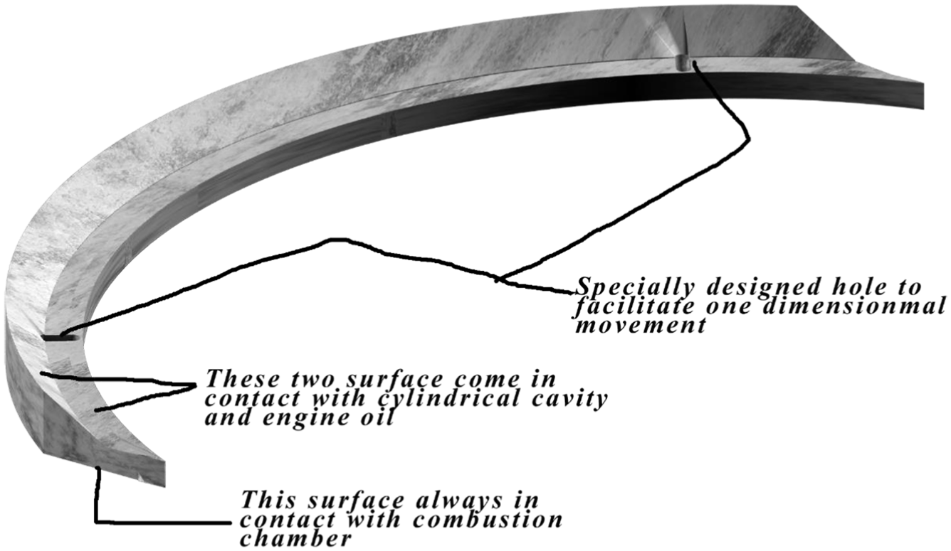
Face seal.
This type of seal have a structural property such that a pressure from compression or combustion event pushes this face seal against the wall of the combustion chamber in order to make the combustion chamber leak proof and further works with great reliability and with efficiency. The face seal has a portion which is always in contact with engine oil and is optionally accompanied by a pleated formed spring and secured to the main wheel by at least two screws such that it can have a radial movement only.
Operation of the engine
The operation of this engine is pretty straightforward and a mere declaration in operating cycle to be as Otto cycle is not likely to be enough to define its operational variety. Rather, it can also be used in CI or diesel cycle as this engine comprises four stroke cycles where suction, compression, combustion, and exhaust cycle can be named accordingly and sequentially. However, a nature of each of its cycle is not as symmetrical as traditional piston engine as shown in Figure 12, that is, its suction and expansion cycle duration is active during more than 180° of power shaft rotation, while each of compression and exhaust cycle duration is active during less than 180° of power shaft rotation, although all the four cycles are completed in two complete rotation of power shaft like the system of traditional piston engine. This type of cycle arrangement exercised by this engine thus provides a significant advantage to this rotary engine as expansion cycle angular duration is larger than that of compression cycle in terms of power shaft rotation, that is, power gets more space or time in order to get transmitted to power shaft in expansion cycle than the time required to compress a gas by power shaft in compression cycle as compression cycle gets comparatively little space or time which can be found after a profound search as shown in Figure 13. If a flywheel is fixedly secured with a power shaft in order to smooth out any fluctuation of speed, then brake fuel efficiency calculated based on expansion and compression work will increase intensely with the increment of compression ratio. In Table 1, a comparative statement or summary is thus provided in order to find broken down parameters on the way of brake fuel efficiency calculation. There is a mathematical derivation to these results which can be found in previous studies.2,3

Four cycles.
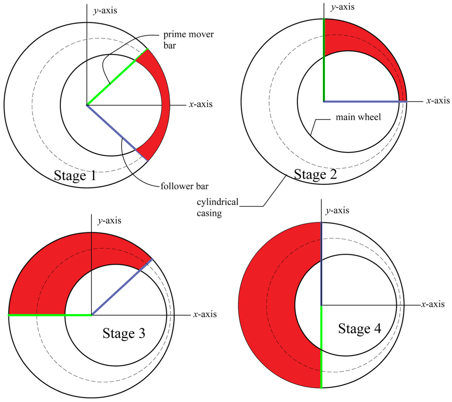
Combustion chamber travels from stage 1 to stage 4 in an expansion cycle.
Comparative efficiency calculation between traditional piston engine and this inventive rotary engine.

This rotary engine basically deals with the perpendicular impact of pressurized gas on prime mover as well as on follower bar wherein the propulsion arises from the deviation of pressure between the two bars, and a direction of propulsion always acts along the dominant force on the bars in the expansion cycle. It is evident that force is the function of pressure and area. So, a difference in exposed area between bars exposed to a perpendicular projection of pressurized gas due to combustion is logically responsible to drive the prime mover or power shaft. In equation referred to in previous studies,2,3 the system basically calculates the average pressure at different stages in expansion cycle and finds the average exposed area in order to find the force that travels along a curved line which may finally provide the work that can also be termed as an expansion work. In similar fashion, the compression work is evaluated and a net energy from fuel is also calculated, and finally by combining these three parameters (expansion work, compression work, and net energy), we can eventually evaluate brake fuel efficiency of this rotary engine for a desired compression ratio. It is also to be noted that the above efficiency values are calculated based on the phenomenon of core operating principle only without any other improvement.
The operation of this rotary engine further comprises a periodic valve lagging in timing between a leading valve and a trailing valve wherein the valve in an inlet valve assembly, that has the sliding contact with the rotating prime mover first, is the leading valve and the other valve in same valve assembly that has the sliding contact with the rotating prime mover followed by the leading valve, is the trailing valve. In the similar manner, the leading valve and the trailing valve can also be defined for an exhaust valve assembly wherein inlet valve assembly and exhaust valve assembly are placed in two distinct positions in the engine module diagram. 7 These valves are proposed as outward opening type as to avoid any collision of radially moving valve with rotating bars where the bars only slide past the valves during rotation. The associated cams are designed in such a way that leading valve and trailing valve will open and close with the contact of the prime mover and the follower bar, respectively. There is a valve seat reserved for each valve as such to limit the valve’s radial movement in the inner circular chamber or in the combustion chamber for further safety from collision. This type of arrangement thus ensures a smooth intake and exhaust of gas.
The main wheel of the engine is designed in such a way that the concentric void can be connected to the non-combustion chamber through a number of sweepers mounted in series within the main wheel such that the concentric void along with non-combustion chamber can be partially filled with engine oil. The sweeper is designed in such a way that it has a natural tendency to sweep away the engine oil from non-combustion chamber to concentric void and further avoiding an unwanted compression in engine oil when the engine is considered to be in operation. However, in the case when multiple engine modules are connected in parallel but in opposite phase, each engine module can communicate with each other by some axial holes proposed inside the casing. This structural setup returns that an unwanted compression in non-combustion chamber of one of the engine modules is neutralized through these axial holes by an unwanted expansion in respective non-combustion chamber of the other engine module which inherently removes unwanted suctional or compressional friction issue in those non-combustion chambers. 7
The fuel for this rotary engine can vary in the range from hydrocarbon to pure hydrogen. A gasoline is primarily chosen for this spark ignition (SI) rotary engine where Otto cycle phenomenon is applicable. Although this rotary engine is designed for Otto cycle, it can also be possible to apply the principle of Diesel cycle or CI engine phenomenon in this rotary engine. A brief description is provided below to illustrate a technique of conversion by a minor modification in existing technology of this rotary engine. Parameters for rotary engine in view of Figure 14 are stated in the following.

Some generic notations.
At BDV,
Here, r is the radius of cylindrical chamber or the length of bars and ŕ is the radius of main wheel.

h is the width of the bars and t is the thickness of each bar
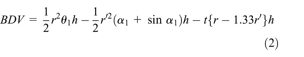
Therefore, the compression ratio is

if thickness of bars is negligible
So, from equation (3), we can see that just only by varying value of r and ŕ, we can eventually get our desired compression ratio. The derivation of those equations is briefly described in previous studies.2,3 Once a compression ratio is evaluated in the zone of CI cycle, one can easily turn the SI engine into CI engine through replacing spark plug by fuel injector, further controlling by optically controlled mechanism which may elevate the overall fuel efficiency up to higher range. However, for the sake of zero emission, a use of hydrogen can replace the use of Diesel or Gasoline which may return a cleaner combustion as well as more power.
However, hydrogen is a fuel that is not readily available on land/atmosphere, and electrolysis or hydrogen extraction from hydrocarbon can be recognized as only two commercially viable sources till date. For electrolysis purpose, it is wise not to use the electricity generated on the land. In this occasion, an alternative system can be adopted by taking advantage of the abundant sea surface to extract electricity by solar panel and further connecting with a pack of Li-ion battery in order to store energy and use the stored energy at night. A Singapore-based company already is taking step to generate hydrogen without chlorine formation from sea water. 4 Moreover, in a process of electrolysis, a good amount of oxygen is also produced, which can be collected and transported through pipe line and further can be emitted in a densely populated area or industrial area in order to restore a balance in eco-system of that area. In an analysis of combustion process, this rotary engine has a specific phenomenon like combustion of air fuel mixture at an adiabatic flame temperature where flame propagation presented in Figure 15 is achieved, which travels toward main wheel and then to bars.

Flame propagation of combustion creates impulses at torque enhancer pocket and enforces combustion chamber to rotate.
At BDV, as there is no difference available in exposed surface area at bars, an impact of flame propagation will be felt only at main wheel due to designed torque enhancer pocket on main wheel itself which is acting along the direction of rotation of power shaft in addition to a forward momentum applied on power shaft by flywheel. This combined momentum will enforce the wheel-bars assembly to rotate from that state when the combustion chamber is beginning to move from BDV to TDV. This threshold or movement of combustion chamber thus enforces geometrically to form a difference in exposed surface area of bars from which event an instantaneous decrease in impact from torque enhancer pocket also takes place as gas pressure is decreased due to an expansion in combustion chamber, which is shown in Figure 16. In this way, the prime mover bar takes over the responsibility gradually from torque enhancer pocket to drive the wheel-bars assembly on its way from BDV to TDV. This kind of driving the wheel-bars assembly continues until no difference in exposed surface area of bars is achieved again at the end of expansion cycle, that is, expansion cycle is concealed by the two consecutive positions where no difference in exposed surface area of bars appear. This basic phenomenon thus provides a power to the power shaft which has a rotational duration more than 180° in expansion cycle, and therefore, consequently, prime mover bar has enough scope/facility to extract/dissipate maximum energy from fuel to power shaft and further ensure a continuous streaming of power delivery beside the forward momentum of flywheel if at least four engine modules in parallel but in opposite phase to each other are designed.
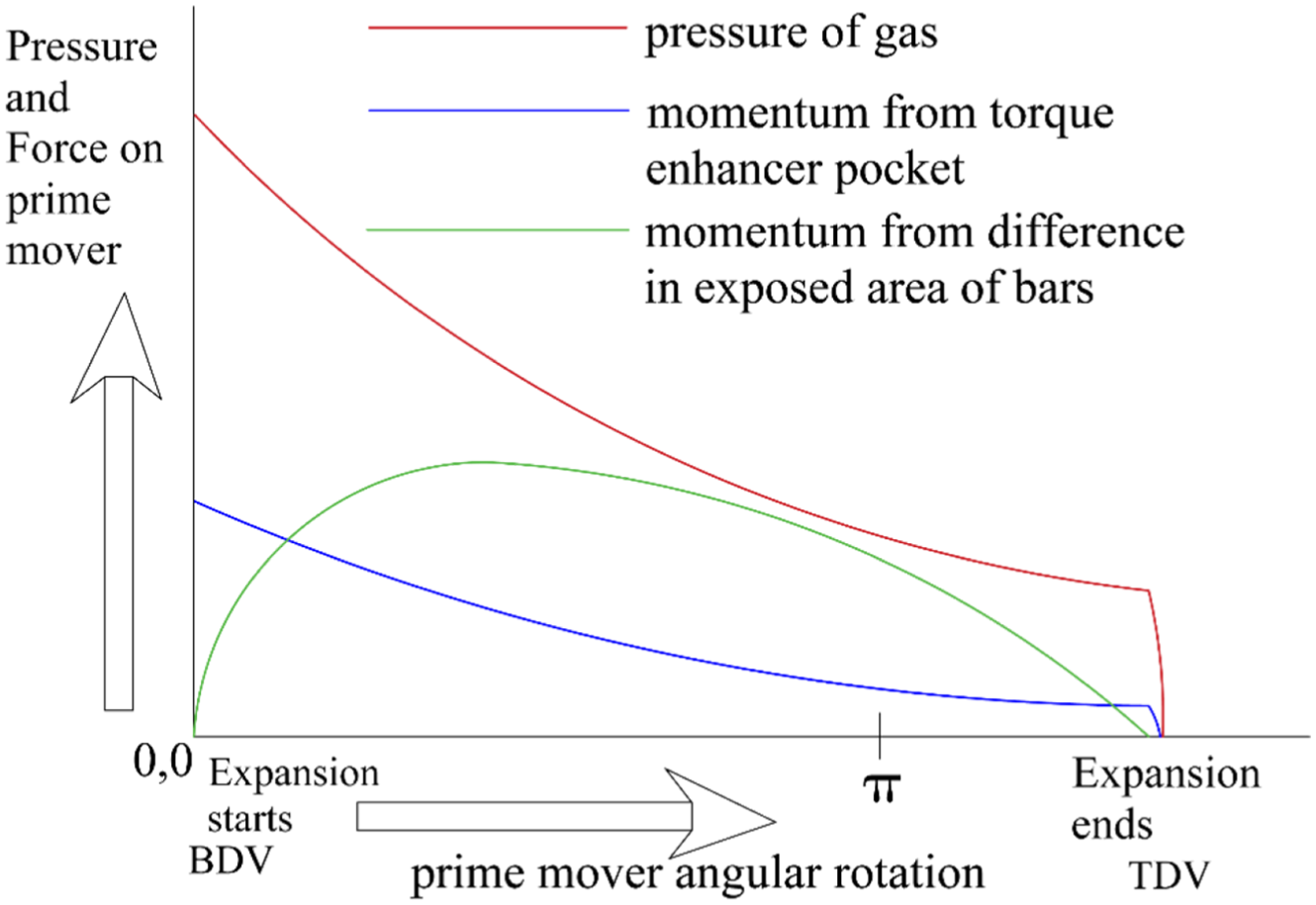
Pressure diagram in expansion cycle.
Conclusion
So, it can be concluded at the end that a phenomenon of formation of compression process is not in any way similar to that of expansion process as the expansion cycle emits the energy perpendicularly/directly to the fixed bar or power shaft in opposition to a process of directly imposing energy to hinged bar by the compression cycle, and most importantly, both the cycles are not accomplished in same way in same place within the engine module. This specific phenomenon in structural operation subsequently introducing long expansion work duration in comparison to compression work duration substantially defines a high ratio of expansion work to compression work. This feature of this rotary engine thus can deliver high torque at high compression ratio with substantially increased efficiency to a power generating plant or system. As this rotary engine has high efficiency and lower emission, substantially it can be the most environmentally-friendly engine in association with/without a cogeneration cycle. However, a cogeneration cycle is not likely very advantageous in terms of cost-effectiveness in powering a vehicle or a hybrid vehicle or a small power plant system, but for a large scaled power plant having capacity more than 1 MW, the cogeneration cycle can work with great reliability and with high efficiency in association with this rotary engine.
Footnotes
Handling Editor: David R Salgado
Declaration of conflicting interests
The author(s) declared no potential conflicts of interest with respect to the research, authorship, and/or publication of this article.
Funding
The author disclosed receipt of the following financial support for the research, authorship, and/or publication of this article: This manuscript has legal and financial involvement with patents US9528433B2 and US10018110B2.