
Abstract
This article presents a dynamic model of ball bearings with a localised defect on the outer raceway to analyse the effect of damping variation on the vibration response of defective bearings. First, a dynamic model is built based on the Hertzian contact theory, the interaction between the bearing inner ring, outer ring, and rolling element; the effect of damping and stiffness is considered; and the vibration equation of the bearing system is solved by the fourth-order Runge–Kutta algorithm. Then, the damping ratios of the experimental bearings using different types of viscosity lubricating grease are measured and compared with the damping ratios of the dynamic model; in addition, the viscous damping coefficient of the experimental bearings are calculated. Finally, the numerical analysis and experimental results show that the grease with a different level of viscosity affects the vibration signal of the defective bearing.
Introduction
The primary function of a lubricant is to lubricate the rolling and sliding contacts of bearings to enhance performance through the prevention of wear and to provide damping forces for bearing contacts. In a bearing model, the damping coefficient used to calculate damping force is one of the important parameters. Many vibration models of bearings take into account the factors of damping.
Poplawski, 1 Harris, 2 and Rumbarger et al. 3 introduced the influence of lubricant film on the theory of rolling bearing quasi-static analysis. Tiwari et al. 4 proposed a model that considers the equivalent damping forces of the inner ring in horizontal and vertical directions. Wang et al. 5 have studied the influence of the clearance and waviness of the motor roller bearing system on the non-linear vibration of the bearings. A bearing model with 4 degrees of freedom is established, and the effects of rotational speed, imbalance force, clearance, damping, and waviness on the vibration response of the model are considered. It shows that the condition of bearing will affect damping. Mitsuya et al. 6 studied the influence of the bearing condition on the damping coefficient through the experiment. The hammer method is used to measure the damping coefficient of the bearings of type 6200 under different clearances, different loads, different rotational speeds, and different lubrication conditions; the damping coefficient ranges from 0.15 to 0.35 N s/mm. The experimental results also show that with the increase of the preload, damping decreases gradually; with the increase of the number of balls and the clearance of the bearing, the damping increases, and the damping increased with the oil film lubrication relative to dry friction. Moreover, the vibration of the bearing is compared under the oil-lubricated and non-lubricated condition. The result showed that the resonance frequency bands are different. Wensing 7 considers that the damping force between the ball and the raceway is related to the viscosity of the lubricant. Moreover, damping also reduces the amplitude of the forced vibration in the resonance region and has little effect on the amplitude away from the resonance region. Nonato and Cavalca 8 proposed a new linear viscous fluid lubrication fitting method to calculate the damping of the bearings and studied the elastic force and damping force of the oil film between the ball and the raceway. The calculation results show that the damping coefficient decreases with the increase of the rotational speed and decreases with the increase of the applied load. Sopanen and Mikkola 9 studied the relationship between the damping and clearance under the static condition of the bearing. The results show that the larger the clearance is, the smaller the damping is. Barabas et al. 10 studied the hydrodynamic behaviour of the large bearing equipped with self-lubricating systems. In the experiment, nanoparticles are added to improve the viscosity and friction coefficient of lubricants. The results show that the contact stresses and the deformation between rollers and raceway decrease with the increase of lubricant viscosity by adding nanoparticles. Zhang et al. 11 established a non-linear dynamic model of high-speed angular contact ball bearings based on the dynamic theory of rolling bearings. Three kinds of aviation lubricants were selected. The dynamic response period of the cage mass centre and the slip ratio of the cage were used as evaluation indexes. The results showed that different lubricants could cause complex periodicity of cage motion. At the same time, the calculation results show that the inappropriate axial force will be detrimental to the stability of the cage. In another paper, Zhang et al. 12 studied the influence of lubricant traction coefficient on the non-linear dynamic behaviour of cage and established a non-linear dynamic model of high-speed cylindrical roller bearings. The simulation results show that under the action of different lubricants, the bearing cage will produce different eddy trajectories. Four kinds of aviation lubricants were used in the experiment. Suggestions on which bearings to use under different working conditions are given.
However, in the vibration model of the defective bearing, the key factor is often the defect problem; the effect of the damping variation on the model is ignored. The value of the damping coefficient in the literature is most of the experience value, and the range of the value is relatively large. Kramer 13 gives the range of the viscosity damping coefficient between the ball and the raceway, but the range of its value is too large. The large amplitude change of the damping coefficient will significantly affect the calculation results of the dynamic model of the bearing. If the value is improper, the bearing dynamic model will not converge when the result is calculated. The bearing damping of the bearing is directly given in the references,14–19 but no basis is given. The damping coefficient between the ball and the raceway is not considered in Patel’s bearing model, and the numerical value and calculation method of the stiffness and damping of the rotating shaft are not given. 20 Ghalamchi et al. 21 roughly estimated the damping ratio of the supporting base and the rotating shaft to 5% as the damping ratio of the model. In Sawalhi’s model, 22 the gear and rotor damping ratios are selected at 5% and 35%. The damping ratio of the balls is set to 5%, and the damping ratio of the bearing base is set to 8%. Choudhury and Tandon 23 adopted the hypothetical damping of Gupta 24 and note that the introduction of hypothetical damping will not significantly change any low-frequency performance, but it can effectively suppress some high-frequency vibration, while the impact force of a rolling bearing with a localised defect can cause high-frequency vibration.
In summary, the clearance, load, speed, and lubricant will change the damping of the bearing. In the past, the value of the damping in the defective bearing vibration model mainly depends on the empirical formula, and for different bearings in different working conditions, the damping value is fixed. This causes the initial parameters of the defective bearing vibration model to be inconsistent with the actual situation, which will affect the final calculation results. To solve this problem, a vibration model of the ball bearing is established based on Hertzian contact theory. The damping ratio of the bearing system is estimated by the experimental measurement; the damping coefficient between the ball and the raceway is calculated according to the damping ratio of the experiment bearing and the proposed model. The effect of damping variation on the vibration response of defective bearings is studied by simulation and experimental results.
The vibration model of bearing system
Bearing system model
The vibration model of the bearing system proposed in this article is shown in Figure 1. The inner ring of the bearing connects with the rotating shaft, and the outer ring and housing are fixed together. The acceleration sensor is installed above the housing, and a load Fl is applied to the housing. Kin and Kout are the contact stiffness between the ball and the raceways, cb is the viscosity damping coefficient, Ks and cs are the elastic coefficient and the structural damping coefficient of the rotating shaft, respectively. The ball-raceway contact is simplified as a spring–mass model, and the whole bearing system is regarded as a spring–mass system. The vibration response of the bearing model is analysed under the following assumptions:
The distance between adjacent balls is equal, and there is no slip.
The forces between ball and raceway only act on the radial direction of the bearing. The contact follows Hertzian contact theory and viscous fluid contact theory.
Grease is used in the bearing, and the viscous damping force between ball and raceway always exists.
When the ball passes through the defect area on the raceway, the stress distribution between the ball and the raceway follows Hertzian contact theory.

The vibration model of the bearing system.
As shown in Figure 2, the inner ring of the ball bearing rotates at a certain speed, and a load is applied to the outer ring. The bearing can be divided into two zones, the load zone and the non-load zone according to the load. In the load zone on the upper part of the bearing, the ball bears the pressure from the inner and outer raceways at the same time. The angle of the load zone is related to the bearing clearance and the load. In the non-load zone, the ball is only subjected to the raceway pressure from the outer raceway.
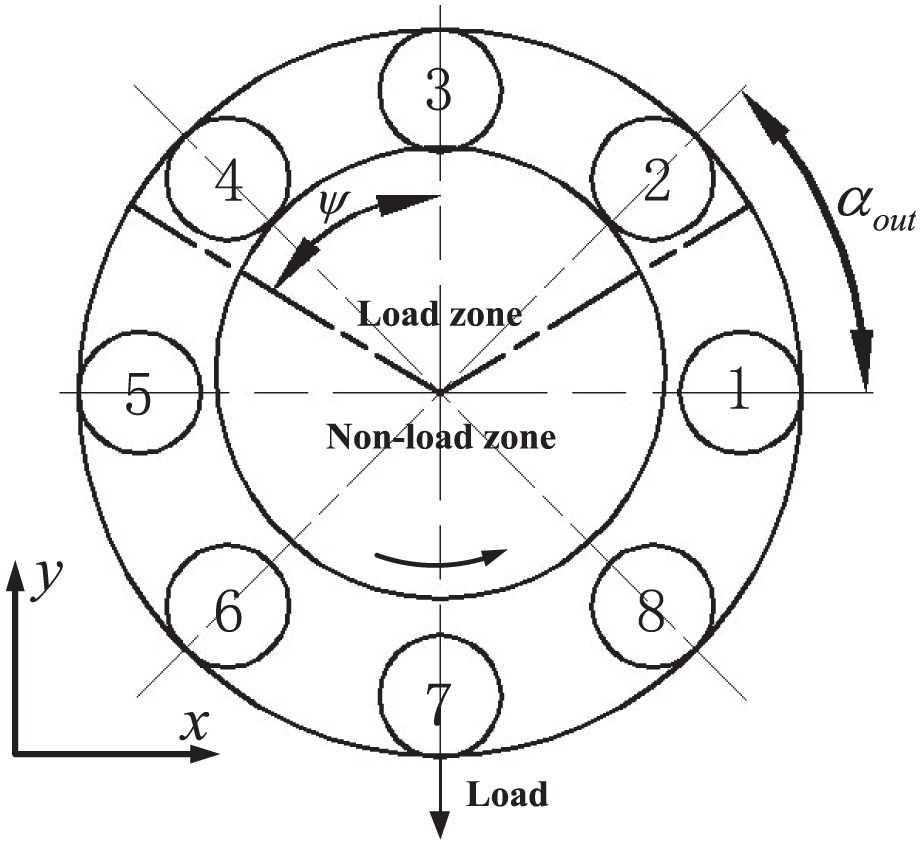
Relative position of bearing parts.
The relative movement relationship between the ball and the raceway is shown in Figure 3. When the ball moves between the inner and outer raceway, it contacts the inner and outer raceway and has elastic deformations.


The motion relationship of the components of a ball bearing.
The distances between the jth ball and centres of the rings are
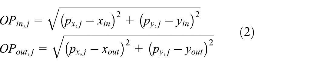
The ball–raceway contact deformations can be expressed as

Calculation of contact force
When the ball contacts the raceway, there are two main forces between them, one is the elastic contact force between the ball and the raceway, and the other is the damping force that can impede the relative motion between the ball and the raceway. According to Hertzian contact theory, the elastic contact force between ball and raceway can be calculated as

where
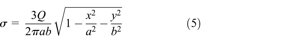
The detailed parameters in equation (5) refer to reference
2
; the parameter Q is the load of the ball, and parameters a and b are the contact area dimension parameters. These three parameters can be expressed by deformation

where s(t) is the contact area between the ball and the raceway, as shown in Figure 4; the contact area is elliptical. When the ball passes the defect position, the contact force between the ball and the raceway near the defect position can be integrated by the stress and the contact area, as shown in equation (7)
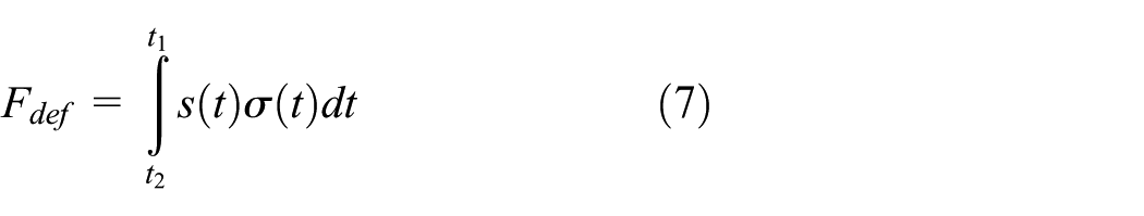
where t1 and t2 are the time when the ball enters and leaves the defect, and its value is related to the relative position between the ball and the rings. The contact force between the jth ball and the raceway can be expressed as

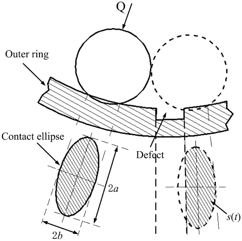
A ball passes the defect.
In horizontal and vertical directions, the contact forces between the balls and the outer ring can be expressed as

The contact forces between all the balls and the inner ring are

Calculation of damping force
In this article, the contact model between the balls and the raceways can be equivalent to the spring–damping model in Figure 5(b), and the damping force is based on the theory of viscous fluid


(a) Contact model of the ball and the raceway and (b) a spring–damping model.
where
According to equation (11), the viscous damping forces between jth ball and inner and outer rings can be expressed as
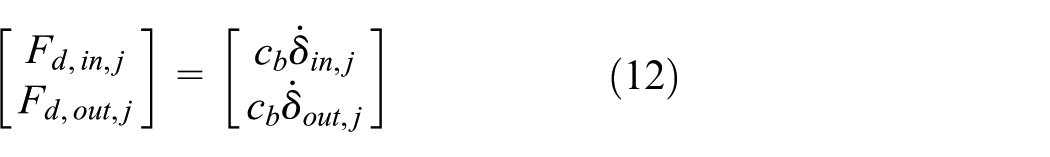
The viscous damping forces between all the balls and rings can be expressed as

Vibration equations of bearing system
According to the bearing model in Figure 2, the vibration equations of the bearing inner and outer rings can be expressed as

For jth ball, the vibration equation in radial direction is

where Min is the mass of the rotating shaft and inner ring, Mout is the mass of the outer ring and housing, m is the mass of a ball, Ks is calculated by the finite element calculation, and the damping of the shaft is calculated using the following 25

The loss coefficient LF is determined by the material and
Calculation of damping coefficient
The general value range of viscous damping coefficient cb between ball and raceway is given in the reference 13

where Klin is the linear stiffness of the bearing, but its range is too large. An appropriate viscosity damping coefficient needs to be calculated by the experiment measurement. At present, only the damping ratio of the bearing system can be measured, and the viscous damping coefficient cannot be obtained. For a bearing with defects, the shock wave generated by the vibration response of the defect signal can be used to measure the damping ratio of the bearing system by the logarithmic attenuation method, as shown in Figure 6.

Calculation of the damping ratio by the logarithmic attenuation method.
The vibration response of the outer ring varies with time, the peak value is A

For a ball bearing using lubricant, the damping ratio can be measured by the logarithmic attenuation method. At the same time, the viscosity damping coefficient cb of the bearing vibration model can be adjusted to make the damping ratio of the bearing vibration model match that of the bearing system measured by the experiment. Therefore, the value of the viscosity damping coefficient cb in the bearing model can be given. The damping ratios of the model and the experimental bearing system must be approximately equal to make cb more accurate.
The flow chart of the numerical computation in this article is shown in Figure 7.

The flow chart of the numerical computation.
Experimental setup
The experimental rig and the bearing (type 6204) are shown in Figure 8. A localised defect which is 0.2 mm wide, 14.0 mm long, and 1.0 mm deep is located on the outer raceway in the vertical in the loaded region. The outer ring is fixed on the housing in the experimental rig. The acceleration sensor is installed on the housing, and a load is applied in the vertical direction, the inner ring and the shaft are fixed together. The parameters of the bearing are shown in Table 1.
Bearing parameters of 6204 type.


(a) Experimental rig and (b) localised defect on the outer raceway.
The three types of lubricating greases used in this experiment are LGHP 2, LGMT 2, and LGEV 2. Their viscosity increases in turn. These three kinds of lubricants are commonly used in industry as bearing lubricants. They are suitable for different situations. Their specific information is listed in Table 2. The viscosity damping coefficient and the effect of the three types of greases on the vibration response signals of the defective bearings will be measured.
The parameters of the lubricating greases.

Calculation and analysis of numerical results
Damping calculation results
According to the above method, the corresponding viscosity damping coefficients of different lubricating greases in various working conditions are shown in Figure 9. It can be seen that the viscosity damping coefficient of the bearing increases with the increase of the viscosity of the grease under the same working condition. For bearings using the same lubricant, the working condition also affects the viscosity damping coefficient. The viscosity damping coefficient decreases with the increase of the speed and decreases with the increase of the bearing load. This is consistent with previous studies by other scholars in reference. 8

Damping coefficient c
Contact force analysis
According to the previous introduction, bearings have a load zone and non-load zone. For the defective ball bearings studied in this article, there is also a defective zone on the outer raceway located at the maximum pressure in the load zone.
The contact forces between the outer raceway and three balls are shown in Figure 10. Balls 2, 3, and 4 pass through the raceway load zone in turn. Two balls have contact with the outer raceway most of the time, and three balls have contact with the raceway only when the middle ball passes through the maximum pressure area. When the ball passes through the defect area, the impact force generated by this ball and the defect will also affect the contact forces between the two adjacent balls and the raceways. When the ball leaves the load zone, the centrifugal force still makes the ball has contact with the outer raceway. However, the mass of the ball is very small (listed in Table 1), the ball-raceway contact force is also very small, about 0.1 N.

Contact force between the balls and the outer raceway.
The contact forces between the ball bearings and the outer race raceway with two different lubricants are shown in Figure 11. The ball passes through the bearing raceway in the following sequence: the non-load zone, the load zone, the defect area, the load zone, and the non-load zone. It can be seen that the contact force between the ball and raceway is very small, almost zero, when the ball is in the non-load zone; after the ball enters the load zone, the contact force increases gradually. When the ball passes through the defect, the contact force changes dramatically with the impact of the defect. Then, the ball enters the load and non-load zone again.

Comparison of contact forces between balls and outer raceway under different lubricants: (a) load: 42.6 N, speed: 1800 r/min; (b) load: 23.0 N, speed: 1800 r/min.
It can be seen that the contact force curves of the bearings with different lubricants in the load zone are distinctly different. The contact force curve of the lubricant LGEV 2 with a larger viscosity fluctuates less, while the contact force curves of the two lubricants in the defect zone exhibit almost no difference. The effect of the lubricant on the contact force is very small when the ball passes the defect, and it is relatively obvious when the ball enters and leaves the load zone.
Numerical signals analysis
The frequency spectra of the numerical signals of the bearings with two different lubricants are shown in Figure 12. The fault characteristic frequency is 92.19 Hz; with the increase of the viscosity of the lubricant, the amplitude of the characteristic frequency decreases, and its harmonics also decrease. It can be seen that the lubricants with different viscosities also affect the frequency spectra of the fault signals.
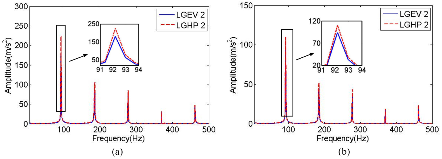
The frequency spectra of the numerical signals with two different lubricants: (a) load: 42.6 N, speed: 1800 r/min; (b) load: 23.0 N, speed: 1800 r/min.
Orbits of the ring centres
The orbits of the inner and outer ring centres are shown in Figure 13. As the outer ring has no elastic support in the X direction, the centre of the outer ring has a larger range of motion in the X direction than that of the inner ring. By comparing the two working conditions, 42.6 N–1800 r/min and 42.6 N–1200 r/min, it can be seen that the larger the rotational speed is, the larger the motion ranges of the inner and outer rings will be in the horizontal direction. By comparing the two working conditions, 42.6 N–1800 r/min and 23 N–1800 r/min, it can be seen that the centre of the ring, which has a larger load, has a lower range of motion. A common characteristic of these three working conditions is that the motion ranges of the inner and outer rings are obviously smaller with the increase of the viscosity of the lubricant; this is more obvious than the effect of lubricant on the vibration response and contact force.
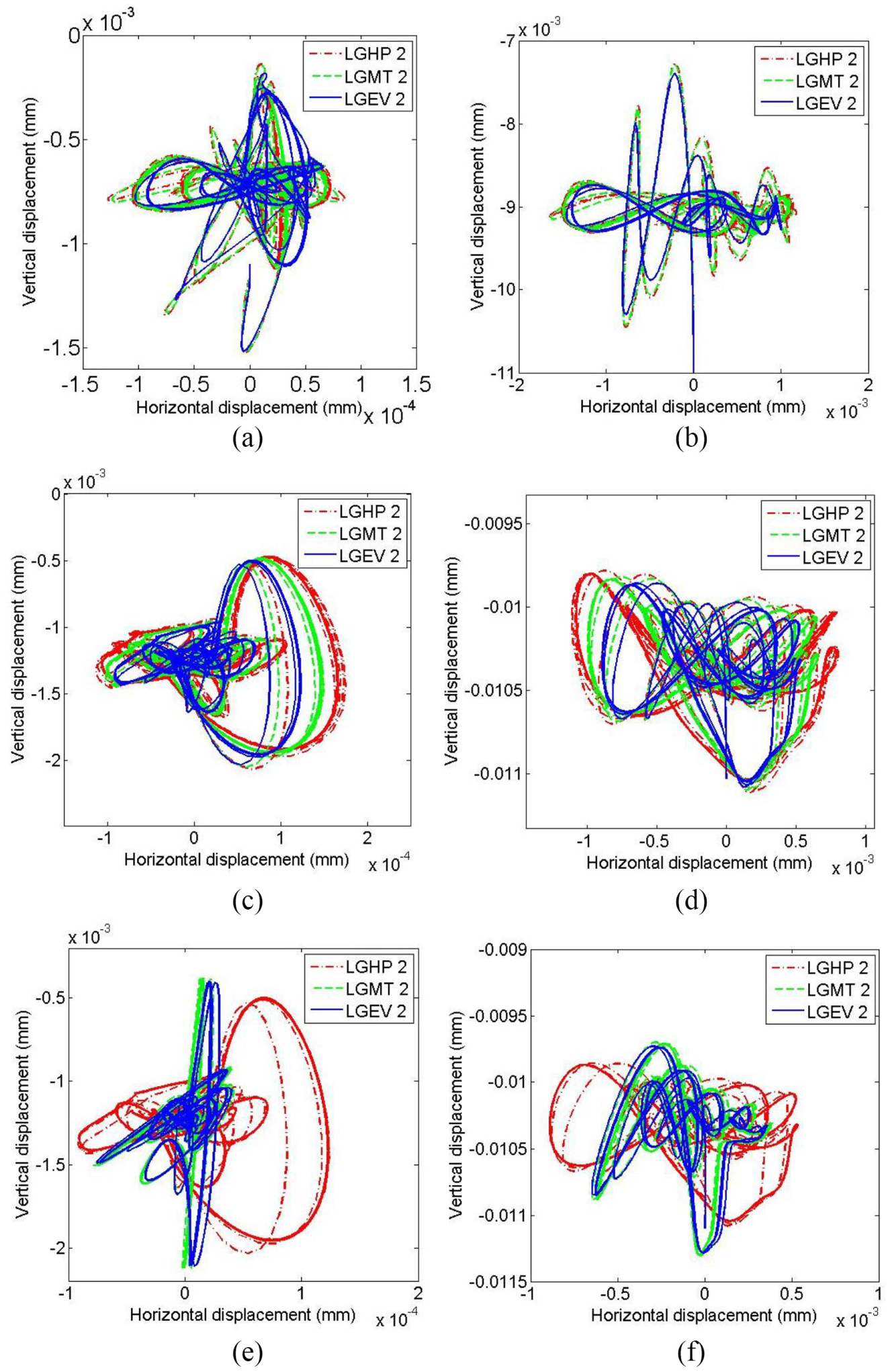
Orbits of the rings: (a) inner ring, load: 23 N, speed: 1800 r/min; (b) outer ring, load: 23 N, speed: 1800 r/min; (c) inner ring, load: 42.6 N, speed: 1800 r/min; (d) outer ring, load: 42.6 N, speed: 1800 r/min; (e) inner ring, load: 42.6 N, speed: 1200 r/min; (f) outer ring, load: 42.6 N, speed: 1200 r/min.
These phenomena occur because the vibration response of the defective bearing is the acceleration signal of the outer ring. The peak of the acceleration of the outer ring is most easily observed on the time domain and frequency domain, but the other change process of the acceleration signal cannot be described in detail. Second, lubricant viscosity does affect the contact force and the motion orbit of the ball when the ball passes the defect, but the effect is only on the defect, and it is not obvious. At the same time, as the change of the contact force and the motion orbit of the ball in the non-defect zone are small, it is easy to ignore the effect of the lubricant on the non-defect zone. In fact, it is a cumulative process. Finally, for the motion orbits of the inner and outer rings, they are the integral values of the acceleration signals of the inner and outer rings, which can fully reflect the cumulative changes of the acceleration signals.
Experimental results analysis
The frequency spectra of the experimental signals with two different lubricants are shown in Figure 14. The amplitudes of the fault characteristic frequency decrease with the increase of the viscosity of the lubricants, and this trend is consistent with that of numerical signals.

The frequency spectra of the experimental signals: (a) load: 23.0 N, speed: 1800 r/min; (b) load: 42.6 N, speed: 1800 r/min.
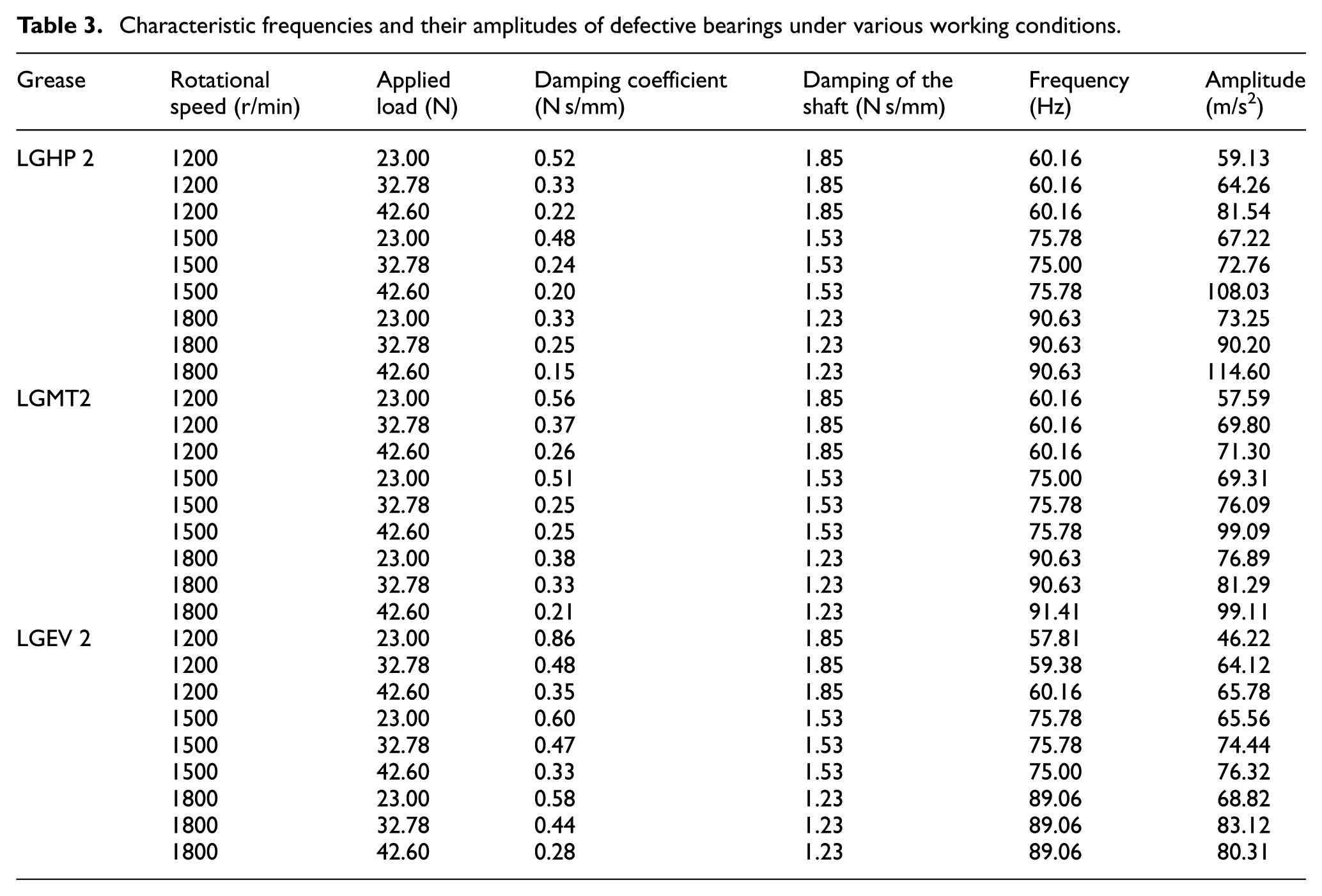
The characteristic frequencies and the vibration amplitudes of the defective bearing under various working conditions are shown in Table 3. It can be seen that with the increase of rotational speed, the characteristic frequency and its vibration amplitude for the defective bearing increase. With the increase of the applied load, the vibration amplitude of characteristic frequency increases; with the increase of the lubricant viscosity, the vibration amplitude decreases, and the trend is very obvious. Although the bearing eccentricity appears in some of the bearing experiments, which affect the experimental results to a certain extent, the different types of lubricants do have a significant effect on the vibration amplitude of the defective characteristic frequency, thus affecting the numerical results of the defective bearing model; therefore, the viscous damping coefficient variation of the bearing caused by the lubricant is a factor similar to the rotational speed and applied load; it must be considered when establishing the vibration model of the defective bearing.
Characteristic frequencies and their amplitudes of defective bearings under various working conditions.
Conclusion
A dynamic model of defective bearing considering viscous damping variation is established in this article. In this model, the damping ratio can be changed by adjusting the viscosity damping coefficient, and the viscous damping coefficient corresponding to the damping ratio of the test defective bearing is obtained. Through the analysis of experimental and simulation data, the effect of damping coefficients on the vibration response of defective bearings was studied. The following conclusions can be drawn as follows:
The contact force curves of the bearings with different lubricants in the load zone are distinctly different. The contact force curves of the lubricants with larger viscosity are less fluctuant, and the contact force curves of the two lubricants exhibit almost no difference in the defect area and non-load zone.
The effect of damping on the motion orbits of the inner and outer rings is more obvious. With the increase of the viscosity damping coefficient, the range of the motion orbits of the inner and outer rings of the bearing gradually decreases, and with the larger applied load, this situation is more obvious.
The vibration amplitudes of the fault characteristic frequency of the bearing with different viscosity lubricating greases are different. With the increase of viscosity, the vibration amplitude decreases. The lubricant is one of the important factors that need to be considered when modelling a defective bearing.
Footnotes
Handling Editor: Crinela Pislaru
Declaration of conflicting interests
The author(s) declared no potential conflicts of interest with respect to the research, authorship, and/or publication of this article.
Funding
The author(s) disclosed receipt of the following financial support for the research, authorship and/or publication of this article: This work was supported by the National Natural Science Foundation of China (51175102) and the Fundamental Research Funds for the Central Universities (grant no. HIT.NSRIF.201638).