The mathematical model and a case study of the cosine face gear drive that has a predesigned fourth order function of transmission errors and a localized bearing contact
Open accessResearch articleFirst published online February, 2019
The mathematical model and a case study of the cosine face gear drive that has a predesigned fourth order function of transmission errors and a localized bearing contact
Traditionally, a face gear drive uses an involute pinion. If the number of teeth of pinion is smaller than the minimum number of teeth without undercutting, the pinion will be undercut. To avoid undercutting, it is necessary to quit using involute pinion. This paper proposes a new face gear drive called cosine face gear drive. The cosine face gear drive has a predesigned fourth order function of transmission errors and a localized bearing contact. Therefore, it has a smoother motion curve and no edge contact problem. According to coordinate transformation theory, the theory of gearing, and differential geometry, the mathematical model of the cosine face gear drive is created, including position vectors, unit normal vectors, principal curvatures, principal directions, the condition of contact, and the condition for producing the predesigned fourth order function of transmission errors. A numerical case is studied to verify the mathematical model. The geometric solid model of the case is created. The actual form of the function of transmission error is analyzed. Contact paths and contact ellipses are analyzed. The effects of assembly errors on contact paths and on the function of transmission errors are analyzed. Contact and fillet stresses are analyzed using finite element analysis.
Face gear drives are used for transmitting motion and torque between two non-parallel, intersecting shafts or non-parallel, non-intersecting shafts. Face gear drives have been applied in aerospace drive system to transfer power between intersecting shafts as found in helicopter rotor transmission. The main advantage of face gear drives is the possibility of the split of torque and the reduction of gear weight.1 Face gear drives are also effective with insufficient lubrication, thus increasing the reliability of the aircraft. Helicopters using transmission systems based on face gear drives have a higher safety and survivability. The use of face gear drives in high power and high precision applications has become more and more popular. Buckingham2 and Dudley3 provided a brief description of face gear drives. Litvin et al.4 developed the analytical geometry of face-gear drives, proposed the method for localization of bearing contact, developed computerized simulation of meshing and bearing contact, investigated the influence of gear misalignment on the shift of bearing contact and transmission errors. Litvin et al.5 conducted computerized generation, localization of bearing contact and simulation of meshing and contact of an orthogonal offset face-gear drive with a spur involute pinion. Litvin et al.6 proposed and investigated new types of face-gear drives for application in transmissions, particularly, in helicopter transmissions, by application of asymmetric profiles and double-crowned pinion of the drive. Their proposed face gear drive was provided with a second order function of transmission errors. Litvin et al.7,8 proposed a new method for generation of face-gears by application of a grinding (or cutting) worm. Two versions of geometry of face-gear drives were considered based on: (i) involute profiles, and (ii) advanced modified profiles of the pinion. Their proposed face gear drive had four main advantages: (i) existence of a longitudinal bearing contact, (ii) avoidance of edge contact, (iii) existence of a second order function of transmission errors, and (iv) reduction of contact stresses. Chung and Chang9 conducted an investigation of contact path and kinematic error for a face gear drive. Zanzi and Pedrero10 investigated an enhanced approach for the application of longitudinal plunging in the manufacturing of a double crowned pinion of a face gear drive to reduce the sensitivity of the gear drive to misalignments. Their proposed face gear drive was provided with a second order function of transmission errors. Litvin et al.11 investigated two versions of face-gear drive geometry with a helical pinion. One version was based on a screw involute helicoid. The second version was a new geometry developed as envelopes of two mismatched parabolic racks of the pinion and the shaper. A new method of grinding or cutting of face-gears by a worm of special shape was developed. Their proposed face gear drive also had four main advantages: (i) existence of a longitudinal bearing contact, (ii) avoidance of edge contact, (iii) existence of a second order function of transmission errors, and (iv) reduction of contact stresses. Tsay and Fong12 proposed a novel profile modification methodology for the molded face-gear drive that enhances the controllability of the contact pattern and transmission characteristics. The contact pattern of the face gear drive was designed in a manner similar to that for the bevel gear, with a localized bearing that reduces the sensitivity of axes misalignment. Tang et al.13 developed a progressive grinding method for spur face-gear. The third action principle of modified spur face-gear driving and the mathematical model of parabolic rack cutter, spur gear cutter, disk wheel and modified spur face-gear were established. Peng et al.14 proposed a manufacturing process for fabricating ease-off surfaces of a face gear drive that was provided with controllable unloaded meshing performance and local bearing contact. A predesigned transmission error, a predesigned contact path, and the length of contact ellipse were applied in the redesign of the ease-off surfaces of the pinion and face gear to control the unloaded meshing performance. Wang et al.15 proposed an efficient honing method for face gear with tooth profile modification to improve the production efficiency of the face gear. The tooth profile of the honing cutter was modified by controlling the longitudinal modification coefficient of the generating rack cutter.
Traditionally, the pinion in a face gear drive is an involute or a modified involute pinion. If the number of teeth of the pinion is smaller than the minimum number of teeth without undercutting, the pinion will be undercut. To replace the involute pinion with a cosine pinion is a way of preventing undercutting. Lee16 proposed a new type of gear drive called cosine gear drive, which was generated using a cosine rack. The minimum number of teeth without undercutting of a cosine gear was smaller than that of an involute gear. Moreover, the maximum fillet stress of a pair of cosine gears was smaller than that of a pair of involute gears.17 By replacing the involute pinion in a face gear drive with a cosine pinion, this paper proposes a new type of face gear drive called cosine face gear drive. The cosine face gear drive is composed of a cosine pinion and a cosine face gear. The cosine face gear is generated by a cosine shaper. The cosine shaper is generated by a cosine rack. The cosine pinion is generated by a form grinding wheel. The axial profile of the form grinding wheel is generated by a planar cosine curve. The cosine face gear drive is designed to have a localized bearing contact to avoid edge contact. More importantly, the cosine face gear drive is designed to have a predesigned fourth order function of transmission errors. Therefore, the cosine face gear drive has a smoother motion curve. Stadtfeld and Gaiser18 in the Gleason Works reported that a fourth order function of transmission errors is superior to a second order one. The motion curve formed by a fourth order function of transmission errors is smoother than the motion curve formed by a second order function of transmission errors. Wang and Fong19 proposed a methodology to synthesize the mating tooth surfaces of a face-milling spiral bevel gear set that transmitted rotations with a predetermined fourth-order motion curve and contact path. Lee20 proposed a method to manufacture a crowned spur gear drive that had a controllable fourth order polynomial function of transmission errors. The level of gear running noise was reduced and edge contact was avoided. Jiang and Fang21 proposed a design of tooth surface modifications to reduce vibration and noise for involute cylindrical gears that were provided with a controllable higher order polynomial function of transmission error. Li et al.22 proposed a function-oriented form-grinding approach to obtain excellent and stable contact performance of cylindrical gears by designing modification forms based on a predesigned controllable fourth-order transmission error function and error sensitivity evaluation. Lee23 proposed a modified involute face gear drive comprising an involute face gear and a crowned pinion. The crowned pinion was generated using a form grinding wheel whose axial profile was a fourth-degree polynomial curve. The modified involute face gear drive had a predesigned fourth order function of transmission errors and dimensionally controllable contact ellipses.
This paper is organized as follows. In section 2, the method to manufacture the cosine face gear is described. The mathematical model of tooth surface of the cosine face gear is developed, including position vector, unit normal vector, principal curvatures and principal directions. In section 3, the method to manufacture the cosine pinion is described. The mathematical model of tooth surface of the cosine pinion is created, including position vector, unit normal vector, principal curvatures and principal directions. In section 4, the mathematical model for tooth contact analysis is established, including the condition of contact, the position vector of contact path, the function of transmission errors, and the dimensions and orientation of a contact ellipse. In section 5, the mathematical model is developed to let the gear drive have a predesigned fourth order function of transmission errors. In section 6, a numerical case of the cosine face gear drive is studied. The geometric solid model of the case is created. The actual values of the function of transmission errors of the case are analyzed. The contact path and contact ellipses of the case are analyzed. The effects of assembly errors on the contact path and on the function of transmission errors of the case are analyzed. Finally, the stresses of the case are analyzed by using finite element analysis.
The mathematical model of tooth surface of the cosine face gear
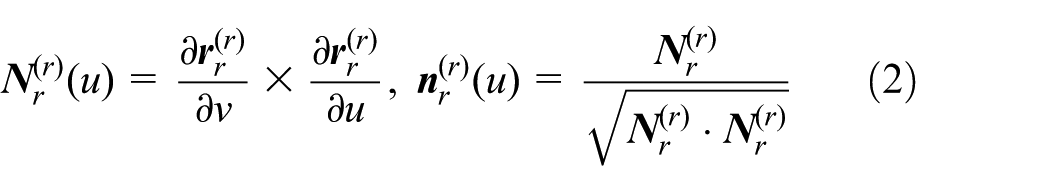
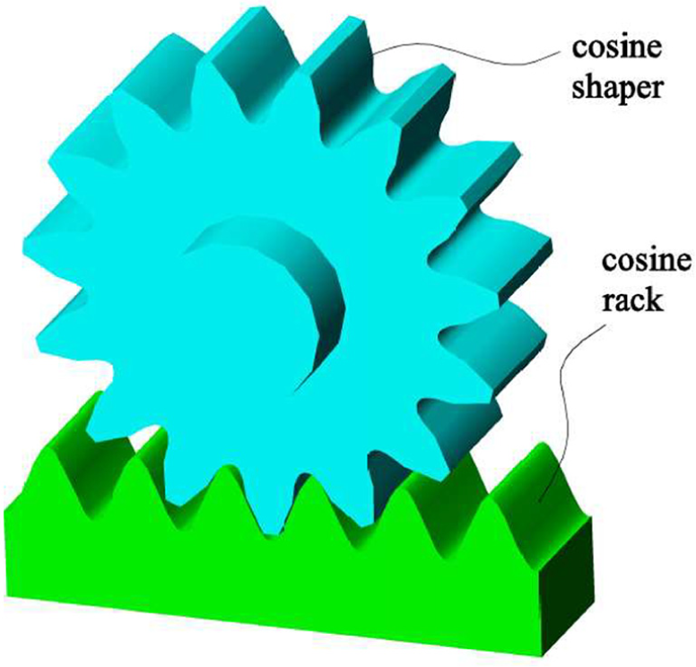
The mathematical model, including position vector, unit normal vector, principal curvatures and principal directions, of tooth surface of the cosine face gear are created in this section. The cosine face gear is manufactured using a cosine shaper. The cosine shaper is manufactured using a cosine rack. In other words, the tooth surface of the cosine rack and the tooth surface of the cosine shaper are a pair of conjugate surfaces. The tooth surface of the cosine shaper and the tooth surface of the cosine face gear are a pair of conjugate surfaces. Here, the tooth surface of the cosine rack is denoted by , the tooth surface of the cosine shaper is denoted by , and the tooth surface of the cosine face gear is denoted by . According to coordinate transformation theory and the theory of gearing,24,25 the mathematical models of and can be determined if the mathematical model of is given. As shown in Figure 1, is the coordinate system connected rigidly to the tooth surface of the cosine rack. The profile of the tooth surface on the plane is a cosine curve. The position vector of the tooth surface represented in is:
Coordinate system connected rigidly to .
The normal and unit normal vectors of the tooth surface represented in are:
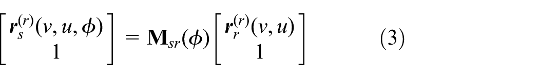
As shown in Figure 2, is the coordinate system connected rigidly to the tooth surface of the cosine shaper. When the tooth surface generates the tooth surface , the tooth surface is provided with a translation and the tooth surface is provided with a rotation. The rotation axis of the tooth surface is . The relative motion between and is also as shown in Figure 2. The translation parameter of is and the rotation parameter of is . The tooth surface of the cosine rack forms a family of surfaces in . According to coordinate transformation theory,24,25 the position vector of represented in is determined by
where is the coordinate transformation matrix from to .
where .
Relative motion between and .
The unit normal vector of represented in is determined by
where is the 3 by 3 submatrix obtained by eliminating the last row and column of .
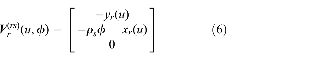
The relative velocity of the tooth surface with respect to the tooth surface represented in is:
According to the theory of gearing,24,25 the necessary condition for the existence of an envelope to the family of surfaces is the following equation of meshing:
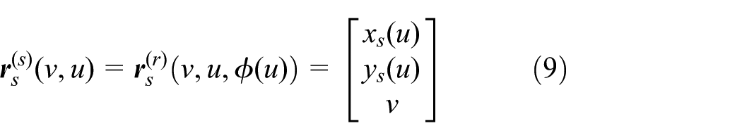
The parameter in equation (7) can be represented as the explicit function of , as follows:
By replacing the parameter in with the explicit function , the position vector of the tooth surface represented in can be obtained as follows:
where
By replacing the parameter in with the explicit function , the unit normal vector of the tooth surface represented in can be obtained as follows:
where
Next, the tooth surface of the cosine shaper is used to generate the tooth surface of the cosine face gear. As shown in Figure 3, is the coordinate system connected rigidly to the tooth surface of the cosine face gear. When the tooth surface generates the tooth surface , the tooth surface is provided with a rotation and the tooth surface is provided with a rotation, too. The rotation axes of and are and , respectively. The relative motion between and is also as shown in Figure 3. The rotation parameters of and are and , respectively. The tooth surface of the cosine shaper forms a family of surface in . According to coordinate transformation theory,24,25 the position vector of represented in is determined by
where is the coordinate transformation matrix from to .
where and .
Relative motion between and .
The unit normal vector of represented in is determined by
where is the 3 by 3 submatrix obtained by eliminating the last row and column of .
The relative velocity of the tooth surface with respect to the tooth surface represented in is:
According to the theory of gearing,24,25 the necessary condition for the existence of an envelope to the family of surfaces is the following equation of meshing:
The parameter in equation (15) can be represented as the explicit function of and , as follows:
By replacing the parameter in with the explicit function , the position vector of the tooth surface represented in can be obtained as follows:
where
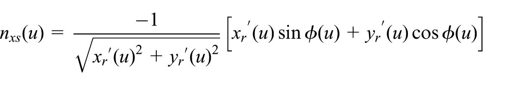
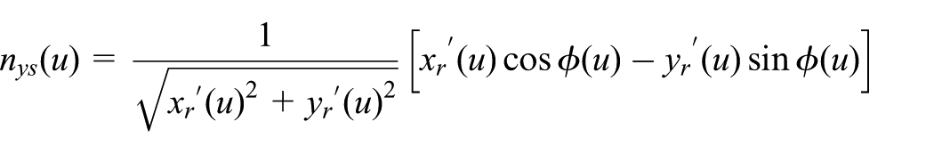
The unit normal vector of the tooth surface represented in can be obtained as follows:
where
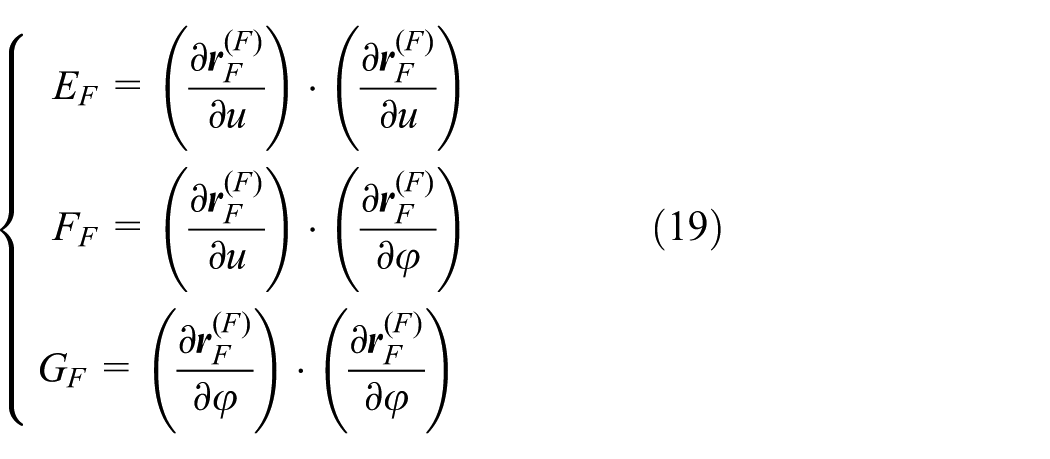
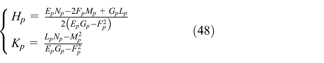
According to the theory in differential geometry, the fundamental quantities of the first kind of the tooth surface are:
The fundamental quantities of the second kind of the tooth surface are:
The mean and total curvatures of the tooth surface are:
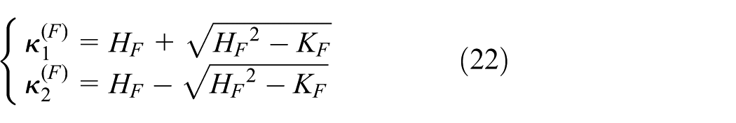
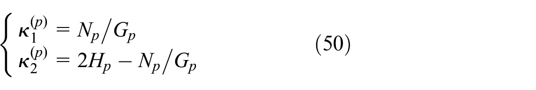
The principal curvatures of the tooth surface are:
Because and , neither nor is the principal direction of . Therefore, the principal directions of the tooth surface represented in are:
where
The mathematical model of tooth surface of the cosine pinion
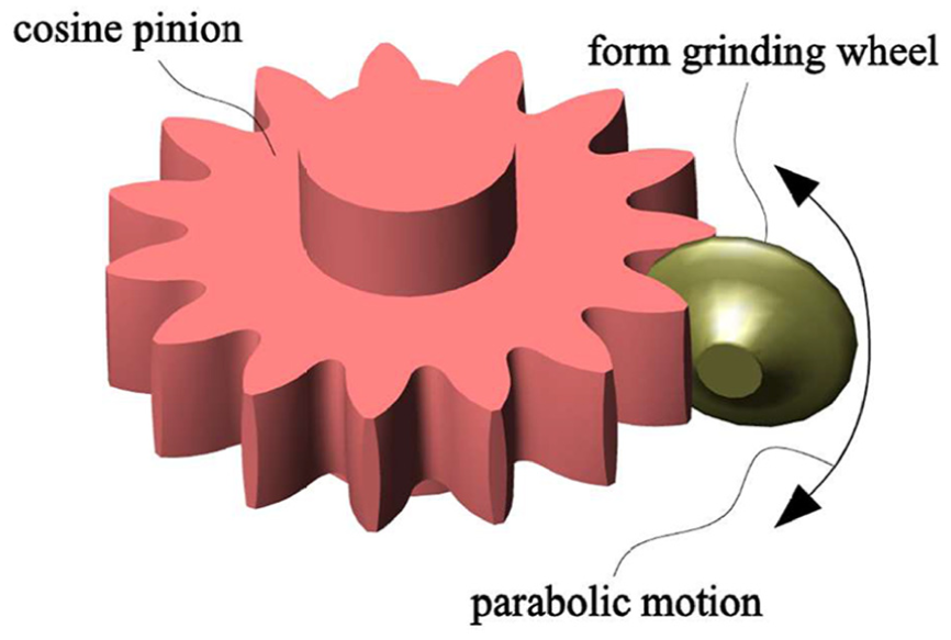
The mathematical model, including position vector, unit normal vector, principal curvatures and principal directions, of tooth surface of the cosine pinion are developed in this section. The cosine pinion is manufactured using a form grinding wheel. The axial profile of the surface of revolution of the form grinding wheel is generated by a planar cosine curve. Here, the planar cosine curve is denoted by . The axial profile of the surface of revolution of the form grinding wheel is denoted by . The surface of revolution of the form grinding wheel is denoted by . The tooth surface of the cosine pinion is denoted by . As shown in Figure 4, is the coordinate system connected rigidly to the planar cosine curve . The position vector of represented in is:
Coordinate system connected rigidly to .
The normal and unit normal vectors of represented in are:
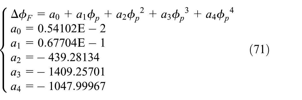
As shown in Figure 5, is the coordinate system connected rigidly to the axial profile . When the planar cosine curve generates the axial profile , the planar cosine curve is provided with a translation and the axial profile is provided with a rotation. The rotation axis of is . The relative motion between and is also as shown in Figure 5. The rotation parameter of is . The translation parameter of is . In order to let the gear drive have a predesigned fourth order function of transmission errors, the translation parameter is designed as follows:
where , and are the design parameters to be determined.
Relative motion between and .
The planar cosine curve forms a family of curves in . According to coordinate transformation theory,24,25 the position vector of represented in is determined by
where is the coordinate transformation matrix from to .
where and .
The unit normal vector of represented in is determined by
where is the 3 by 3 submatrix obtained by eliminating the last row and column of .
The relative velocity of the planar cosine curve with respect to the axial profile represented in is:
According to the theory of gearing,24,25 the necessary condition for the existence of an envelope to the family of curves is the following equation of meshing:
The equation of meshing in equation (31) can be simplified as follows:
The position vector of the axial profile represented in is determined by
The unit normal vector of the axial profile represented in is determined by
The surface of revolution of the form grinding wheel can be obtained after the rotation of the axial profile about the axis of revolution of the form grinding wheel. As shown in Figure 6, is the coordinate system connected rigidly to the surface of revolution . The rotation axis of the axial profile is . The relationship between and is also as shown in Figure 6. According to coordinate transformation theory,24,25 the position vector of the surface of revolution represented in is determined by
where is the coordinate transformation matrix from to .
Relationship between and .
The unit normal vector of the surface of revolution represented in is determined by
where is the 3 by 3 submatrix obtained by eliminating the last row and column of .
Next, the surface of revolution of the form grinding wheel is used to generate the tooth surface of the cosine pinion. As shown in Figure 7(a), and are the coordinate systems connected rigidly to the tooth surface . When the surface of revolution of the form grinding wheel generates the tooth surface , the surface of revolution is provided with a parabolic motion with respect to the tooth surface . The relative motion between and is as shown in Figure 7(b). The surface of revolution forms a family of surface in . According to coordinate transformation theory,24,25 the position vector of represented in is determined by
where is the coordinate transformation matrix from to .
(a) Relationship between and and (b) relative motion between and .
The unit normal vector of represented in is determined by
where is the 3 by 3 submatrix obtained by eliminating the last row and column of .
The relative velocity of the surface of revolution with respect to the tooth surface represented in is:
According to the theory of gearing,24,25 the necessary condition for the existence of an envelope to the family of surfaces is the equation of meshing shown as follows:
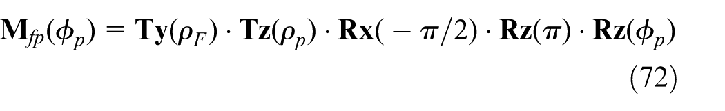
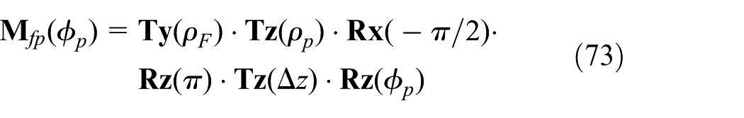
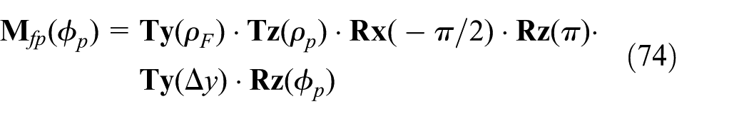
The parameter in equation (42) can be represented as the explicit function of , as follows:
By replacing the parameter in with the explicit function , the position vector of the tooth surface of the cosine pinion represented in can be obtained as follows:
Since does not have the parameter , the unit normal vector of the tooth surface of the cosine pinion represented in can be obtained as follows:
According to the theory in differential geometry and the chain rule in calculus, the fundamental quantities of the first kind of the tooth surface are:
The fundamental quantities of the second kind of the tooth surface are:
The mean and total curvatures of the tooth surface are:
Because , the unit vector in the direction of is one of the two principal directions of . Therefore, the principal directions of the tooth surface represented in are:
The principal curvatures of the tooth surface are:
The mathematical model for tooth contact analysis
The tooth surface of the cosine pinion and the tooth surface of the cosine face gear are a pair of point-contact conjugate surfaces. As shown in Figure 8, and are the fixed coordinate systems connected rigidly to the gear housing of the cosine face gear drive, is the coordinate system connected rigidly to the tooth surface of the cosine pinion, and is the coordinate system connected rigidly to the tooth surface of the cosine face gear. The rotation axes of and are and , respectively. The rotation angles of and are and , respectively. The condition of contact is the following mathematical model:
where
is the coordinate transformation matrix from to . is the coordinate transformation matrix from to . is the 3 by 3 submatrix obtained by eliminating the last row and column of . is the 3 by 3 submatrix obtained by eliminating the last row and column of . Because , there are only six independent equations in equation (51). In other words, a system of equations with six independent equations and seven unknowns, , , , , , and , is determined by equation (51). According to the theorem for the existence of an implicit function system, the system of six independent equations determines the following six implicit functions.
Relationship among , and .
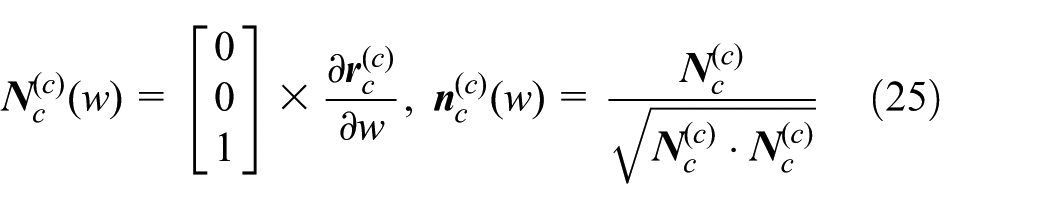
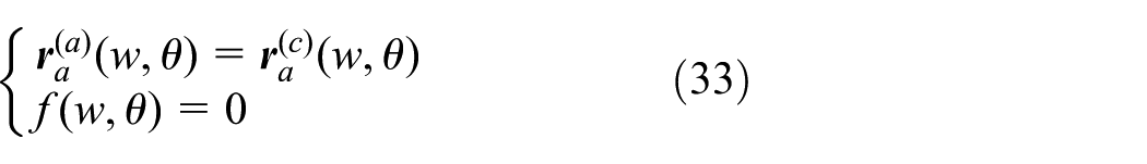
Using , and in equation (52), the contact path on the tooth surface can be determined by
Using , and in equation (52), the contact path on the tooth surface can be determined by
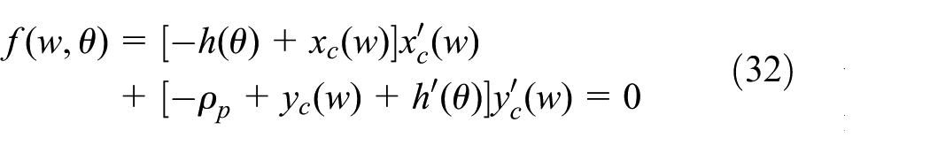
Using in equation (52), the function of transmission errors can be determined by
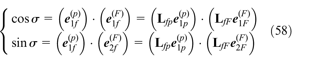
Due to the elasticity of materials, the theoretical contact point is spread over a contact area. The projection of the contact area on the common tangent plane of and is an ellipse if and are approximated by their second order Taylor series expansions.24,25Figure 9 shows the model of a contact ellipse. The common tangent plane of and is . The center of the contact ellipse is the theoretical contact point. The major and minor axes of the contact ellipse are and , respectively. The orientation of the contact ellipse is determined by the angles and . The angle measured counterclockwise from to is . The angle measured counterclockwise from to is . If the elastic approach between and is given, the major and minor axes can be determined using the following equations:24,25
where
Model of a contact ellipse.
The parameters , , and can be determined using the following equations:
The angle can be determined using the following equations:
The angle can be determined using the following equations:
The mathematical model for producing the predesigned fourth order function of transmission errors
The cosine face gear drive proposed in this paper can have a predesigned fourth order function of transmission errors if the design parameters, , , and , are given correctly. In other words, to let the cosine face gear drive have a predesigned fourth order function of transmission errors, the values of , , and must be determined correctly. In this section, a system of equations that contains thirteen nonlinear equations is developed to determine the values of , , and , correctly. According to equation (55), the tangent slope of the function of transmission errors is:
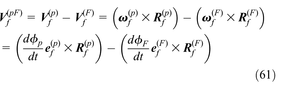
The relative velocity of the tooth surface with respect to the tooth surface represented in is:
Since the tooth surface and the tooth surface are a pair of conjugate surfaces, the inner product of the unit normal vector and the relative velocity is zero.
After substituting equation (61) into equation (62), the derivative of with respect to is obtained as follows:
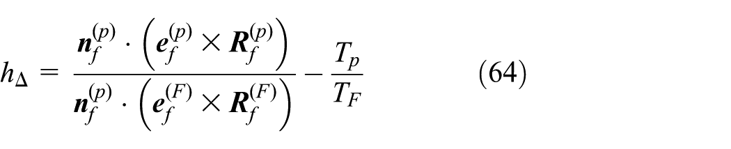
After substituting equation (63) into equation (60), the mathematical model for determining the tangent slope of the function of transmission errors is obtained as follows:
where
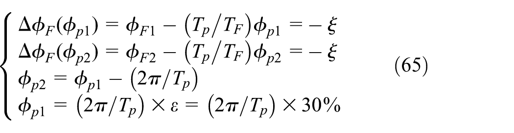
Figure 10 shows the model of the predesigned fourth order function of transmission errors. When the tooth surface contacts the tooth surface at point , the old six parameters, , , , , , and , are replaced by the new six parameters, , , , , , and , respectively. When the tooth surface contacts the tooth surface at point , the old six parameters, , , , , , and , are replaced by the new six parameters, , , , , , and , respectively. At points and , the value of the predesigned fourth order function of transmission errors is . Therefore, , , and have the following relations:
Model of the predesigned fourth order function of transmission errors.
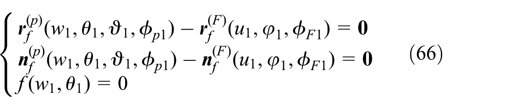
Based on equation (51), the condition of contact for point is as follows:
Based on equation (51), the condition of contact for point is as follows:
Moreover, the tangent slope of the predesigned fourth order function of transmission errors at point is zero, which means
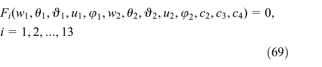
Because , equations (66) and (67) have twelve independent algebraic equations. The twelve independent equations and the one equation in equation (68) form a system of equations that has thirteen equations and thirteen unknowns: , , , , , , , , , , , and . The system of equations, which is called the condition for producing the predesigned fourth order function of transmission errors, can be represented as follows:
The Newton’s root finding method can be used to solve the system of equations to determine the thirteen unknowns. To determine the initial guesses of the thirteen unknowns, an optimization model based on equation (69) is developed as follows:
The optimization model can be solved using a global search algorithm. The solutions of unknowns obtained by the global search algorithm are transferred to the Newton’s root finding method to be the initial guesses of unknowns.
A numerical case study
A numerical case is studied herein to verify the mathematical models that have been built in previous sections. To perform this study, seven steps are applied as follows.
Step 1: creating the cosine rack and the cosine shaper
The gear module is set to 10 mm. The dedendum height is set to . The number of teeth of the cosine shaper is set to 15. Using the position vector of tooth surface of the cosine rack in equation (1) and the position vector of tooth surface of the cosine shaper in equation (9), the geometric solid models of the cosine rack and the cosine shaper are created as shown in Figure 11.
Geometric solid models of the cosine rack and the cosine shaper.
Step 2: creating the cosine face gear
The number of teeth of the cosine face gear is set to 30. Using the position vector of the tooth surface of the cosine face gear in equation (17), the geometric solid model of the cosine face gear is created as shown in Figure 12.
Geometric solid models of the cosine shaper and the cosine face gear.
Step 3: creating the form grinding wheel and the cosine pinion
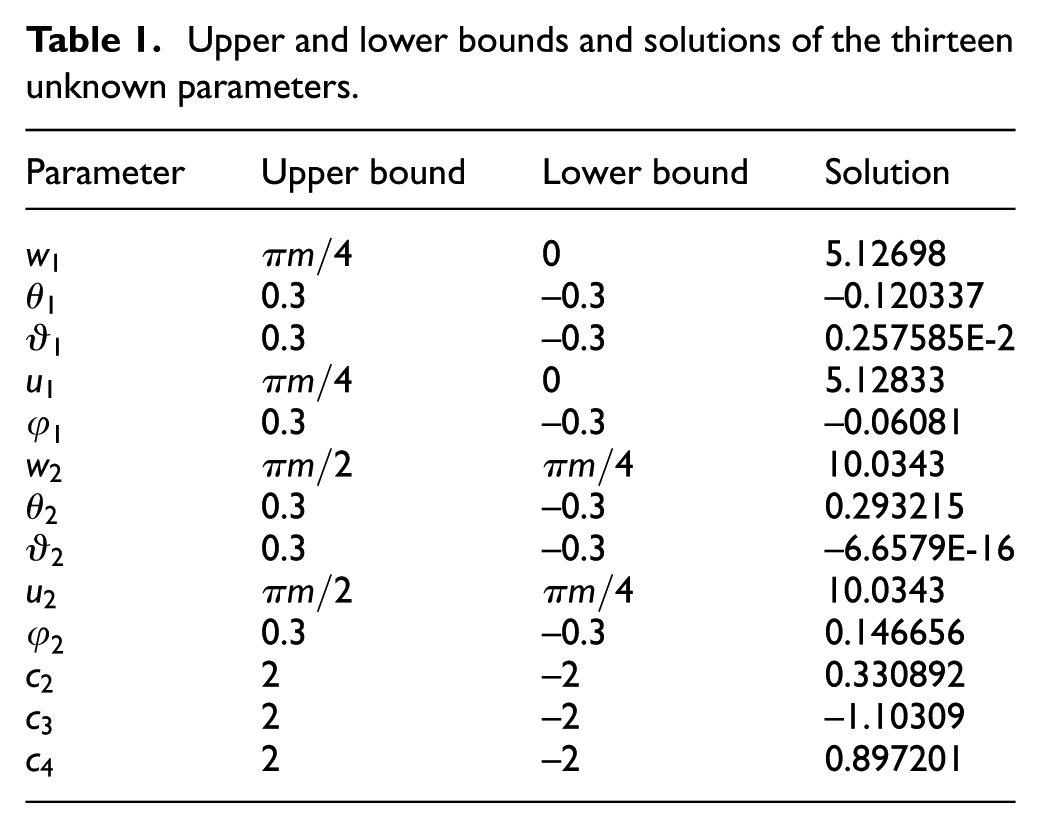
The number of teeth of the cosine pinion is set to 15. The parameter of the parabolic motion of the form grinding wheel is set to 0.003. The radius parameter of the form grinding wheel is to 20 mm. The amplitude of the predesigned fourth order function of transmission errors is set to 10 arcsec. A differential evolution algorithm is applied to solve the optimization problem in equation (70). A Newton’s root finding algorithm is applied to solve the system of equations in equation (69). Before executing the differential evolution algorithm, the upper and lower bounds of the thirteen unknowns are set as shown in Table 1. The solutions of the unknowns obtained by the differential evolution algorithm are regarded as the initial guesses of the unknowns and are transferred to the Newton’s rooting finding algorithm. The solutions of the unknowns obtained by the Newton’s root finding algorithm are also as shown in Table 1. Until now, the three unknown design parameters, , and , in the function has been determined. Then, the axial profile and the surface of revolution of the form grinding wheel can be determined. Using the position vector of in equation (35) and the position vector of in equation (44), the geometric solid models of the form grinding wheel and the cosine pinion are created as shown in Figure 13. After assembling the cosine pinion and the cosine face gear, the geometric solid model of the cosine face gear drive is obtained as shown in Figure 14.
Upper and lower bounds and solutions of the thirteen unknown parameters.
Parameter
Upper bound
Lower bound
Solution
0
5.12698
0.3
–0.3
–0.120337
0.3
–0.3
0.257585E-2
0
5.12833
0.3
–0.3
–0.06081
10.0343
0.3
–0.3
0.293215
0.3
–0.3
–6.6579E-16
10.0343
0.3
–0.3
0.146656
2
–2
0.330892
2
–2
–1.10309
2
–2
0.897201
Geometric solid models of the form grinding wheel and the cosine pinion.
Geometric solid model of the cosine face gear drive.
Step 4: analyzing the actual values of the function of transmission errors
Solving the system of equations for the condition of contact in equation (51), the actual values of the function of transmission errors, , is calculated as shown in Table 2. The actual form of the function of transmission errors is plotted as shown in Figure 15. Using the method of regression analysis and the data of and in Table 2, the regression polynomial model of the function of transmission errors can be determined as follows:
Results of tooth contact analysis and contact ellipses analysis.
(rad)
(arcsec)
(mm)
(mm)
–0.29322
–10
4.97591
1.14948
–0.26656
–9.82355
4.84010
1.07185
–0.23990
–9.30864
4.71039
1.03554
–0.21325
–8.49021
4.58972
1.02105
–0.18659
–7.41941
4.48109
1.01880
–0.15994
–6.16205
4.38610
1.02360
–0.13328
–4.79746
4.30533
1.03251
–0.10662
–3.41761
4.23882
1.04389
–0.07997
–2.12650
4.18642
1.05696
–0.05331
–1.03978
4.14807
1.07155
–0.02666
–0.28463
4.12406
1.08807
0.00000
0.00000
4.11540
1.10757
0.02513
–0.29843
4.12340
1.13039
0.05027
–1.28769
4.15133
1.16029
0.07540
–3.11865
4.20830
1.20208
0.10053
–5.95871
4.31664
1.26508
0.12566
–10
4.54667
1.37084
Actual form of the function of transmission errors.
The R-squared value of the regression polynomial model is 1, which means the regression polynomial model fits the data perfectly. It can be seen that the function of transmission errors is indeed a fourth order polynomial function. To let the cosine face gear drive have a predesigned fourth order function of transmission is successfully realized.
Step 5: analyzing the dimensions and orientation of contact ellipses
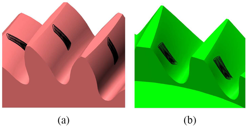
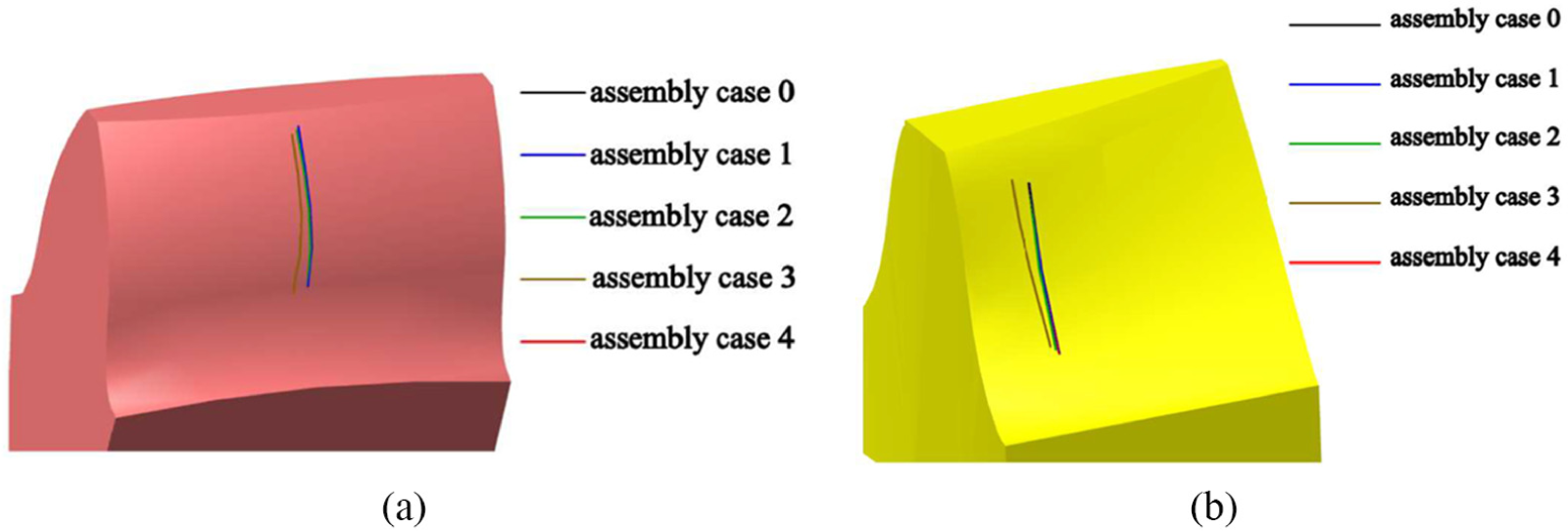
Usually, the contact ellipse is considered for the case when the gears are under a small load and is taken to be 0.00025 inch.24,25 Therefore, the elastic approach between and is set to 0.006 mm. The dimensions and orientation of a contact ellipse can be determined by using equations (56)–(59). Table 1 shows the results of major and minor axes of the contact ellipses in a cycle of meshing. Using equations (53) and (56)–(59), the contact path and contact ellipses on the tooth surface of the cosine pinion are plotted as shown in Figure 16(a). Using equations (54) and (56)–(59), the contact path and contact ellipses on the tooth surface of the cosine face gear are plotted as shown in Figure 16(b). Because the bearing contact, which is formed by the set of contact ellipses, is away from the boundaries of tooth surface, the cosine face gear drive has no edge contact problem.
Contact path and contact ellipses on (a) the tooth surface and (b) the tooth surface .
Step 6: analyzing the effects of assembly errors on the location of contact path and on the function of transmission errors
To analyze the effects of assembly errors on the location of contact path and on the function of transmission errors, five assembly cases are considered herein. Figure 17(a) shows the relationship between and for assembly case 0, where the cosine pinion is provided with no assembly errors. The coordinate transformation matrix from to is as follows:
Relationship between and for (a) assembly case 0, (b) assembly case 1, (c) assembly case 2, (d) assembly case 3, and (e) assembly case 4.
Figure 17(b) shows the relationship between and for assembly case 1, where the cosine pinion is provided with a distance assembly error along the direction . The coordinate transformation matrix from to is as follows:
Figure 17(c) shows the relationship between and for assembly case 2, where the cosine pinion is provided with a distance assembly error along the direction . The coordinate transformation matrix from to is as follows:
Figure 17(d) shows the relationship between and for assembly case 3, where the cosine pinion is provided with an angular assembly error on the horizontal plane . The coordinate transformation matrix from to is as follows:
Figure 17(e) shows the relationship between and for assembly case 4, where the cosine pinion is provided with an angular assembly error on the vertical plane . The coordinate transformation matrix from to is as follows:
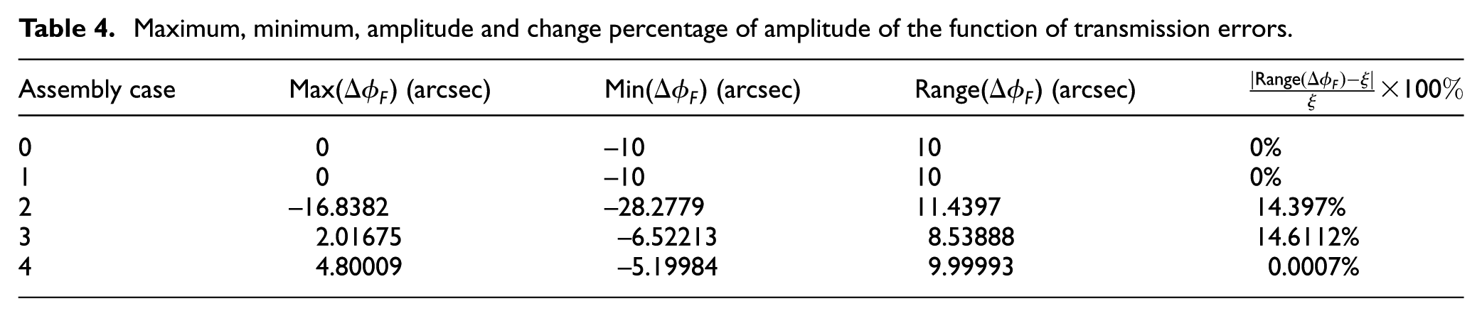
The setting of assembly errors for the five assembly cases is as shown in Table 3. The distance assembly errors and are set to 0.03 mm and 0.03 mm, respectively. The angular assembly errors and are set to 0.2 degree and 0.2 degree, respectively. After executing tooth contact analysis, the effects of the assembly errors on the location of the contact path on are plotted as shown in Figure 18(a); the effects of the assembly errors on the location of the contact path on are plotted as shown in Figure 18(b). It can be seen that the assembly error has the largest impact on the locations of the contact paths. The other assembly errors have very little impact on the locations of the contact paths. The effects of the assembly errors on the function of transmission errors, , are plotted as shown in Figure 19. It can be seen that all curves of remain continuous. Although the assembly errors can influence the location of , they cannot influence the pattern of . The maximum, minimum, amplitude and change percentage of amplitude of are as shown in Table 4. Although the assembly errors can influence the maximum and minimum of , they cannot influence greatly the amplitude of . The assembly error has the largest impact on the amplitude of . The assembly error has the second largest impact on the amplitude of . The assembly error has a very small impact on the amplitude of . The assembly error has no impact on the amplitude of .
Setting of assembly errors.
Assembly case
(mm)
(mm)
(degree)
(degree)
0
0
0
0
0
1
0.03
0
0
0
2
0
0.03
0
0
3
0
0
0.2
0
4
0
0
0
0.2
Maximum, minimum, amplitude and change percentage of amplitude of the function of transmission errors.
Assembly case
Max() (arcsec)
Min() (arcsec)
Range() (arcsec)
0
0
–10
10
0%
1
0
–10
10
0%
2
–16.8382
–28.2779
11.4397
14.397%
3
2.01675
–6.52213
8.53888
14.6112%
4
4.80009
–5.19984
9.99993
0.0007%
Effects of the assembly errors on (a) the contact path on and (b) the contact path on .
Effects of the assembly errors on the function of transmission errors.
Step 7: analyzing stresses by using finite element analysis
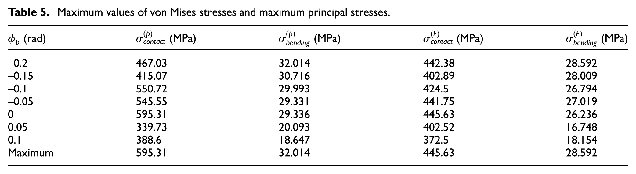
Finite element analysis software ANSYS Workbench is applied herein to perform the finite element stress analysis for the numerical case. Figure 20 shows the finite element model created using ANSYS Workbench. The angular position of the cosine pinion, , is set to 0. The type of elements used to build the finite element model is set to SOLID186, which is a higher order 3-D 20-node solid element that exhibits quadratic displacement behavior. The material of the finite element model is set to structural steel. The Young’s modulus of the material is set to 2E5 MPa. The Poisson’s ratio of the material is set to 0.3. The bottom plane of the cosine face gear is fixed. The radial and axial displacements of the bottom cylindrical surface of the cosine pinion are set to 0. The tangential displacement of the bottom cylindrical surface of the cosine pinion is set to free. The moment applied on the bottom cylindrical surface of the cosine pinion is set to 110000 N-mm. Figure 21(a) shows the results of von Mises stresses of the cosine pinion. Figure 21(b) shows the results of von Mises stresses of the cosine face gear. Figure 22(a) shows the results of maximum principal stresses in the fillet of the cosine pinion. Figure 22(b) shows the results of maximum principal stresses in the fillet of the cosine face gear. Here, the maximum value of the von Mises stresses and the maximum value of the maximum principal stresses of the cosine pinion are denoted by and , respectively. The maximum value of the von Mises stresses and the maximum value of the maximum principal stresses of the cosine face gear are denoted by and , respectively. The results of , , and in different are analyzed as shown in Table 5. The maximum of is 595.31 MPa. The maximum of is 445.63 MPa. The maximum of is 32.014 MPa. The maximum of is 28.592 MPa. Therefore, the contact stress safety factor of the cosine face gear is about 1.34 times of that of the cosine pinion. The bending stress safety factor of the cosine face gear is about 1.12 times of that of the cosine pinion.
Maximum values of von Mises stresses and maximum principal stresses.
(rad)
(MPa)
(MPa)
(MPa)
(MPa)
–0.2
467.03
32.014
442.38
28.592
–0.15
415.07
30.716
402.89
28.009
–0.1
550.72
29.993
424.5
26.794
–0.05
545.55
29.331
441.75
27.019
0
595.31
29.336
445.63
26.236
0.05
339.73
20.093
402.52
16.748
0.1
388.6
18.647
372.5
18.154
Maximum
595.31
32.014
445.63
28.592
Finite element model created using ANSYS Workbench.
von Mises stresses of (a) the cosine pinion and (b) the cosine face gear.
Maximum principal stresses in the fillet of (a) the cosine pinion and (b) the cosine face gear.
Conclusions
This paper has proposed the mathematical model and conducted a case study of the cosine face gear drive that has a predesigned fourth order function of transmission errors and a localized bearing contact. The mathematical model of the cosine face gear drive includes the position vectors, unit normal vectors, principal curvatures and principal directions of tooth surfaces, the condition of contact, the dimensions and orientation of a contact ellipse, and the condition for producing the predesigned fourth order function of transmission errors. A numerical case study has been conducted to verify the mathematical model. According to the results of the case, the actual form of the function of transmission errors is indeed a fourth order polynomial function. The bearing contacts are localized and away from the boundaries of tooth surfaces. So, there is no edge contact problem. The location of contact path is not sensitive to assembly errors. The pattern and amplitude of the fourth order function of transmission errors are not sensitive to assembly errors. According to the stresses analyzed using ANSYS Workbench, the contact stress safety factor of the cosine face gear is about 1.34 times of that of the cosine pinion. The bending stress safety factor of the cosine face gear is about 1.12 times of that of the cosine pinion.
Footnotes
Appendix 1
Handling Editor: Xiaodong Sun
Declaration of conflicting interests
The author(s) declared no potential conflicts of interest with respect to the research, authorship, and/or publication of this article.
Funding
The author(s) disclosed receipt of the following financial support for the research, authorship, and/or publication of this article: The author gratefully acknowledges the financial support provided to this study by Cheng Shiu Univeristy under grant number 105C13.
ORCID iD
Cheng-Kang Lee
References
1.
LitvinFLWangJCBosslerRBet al. Face-gear drives: design, analysis and testing for helicopter transmission applications. AGMA paper 92FTM2, 1992.
2.
BuckinghamE. Analytical mechanics of gears. New York: Dover, 1949.
3.
DudleyDW. Gear handbook: the design, manufacture, and application of gears. New York: McGraw-Hill, 1962.
4.
LitvinFLZhangYWangJCet al. Design and geometry of face-gear drives. J Mech Des1992; 114: 642–647.
5.
LitvinFLEgeljaATanJet al. Computerized design, generation and simulation of meshing of orthogonal offset face-gear drive with a spur involute pinion with localized bearing contact. Mech Mach Theory1998; 33: 87–102.
6.
LitvinFLFuentesAHowkinsM. Design, generation, and TCA of new type of asymmetric face-gear drive with modified geometry. Comput Method Appl M2001; 190: 5837–5865.
7.
LitvinFLFuentesAZanziCet al. Design, generation, and stress analysis of two versions of geometry of face-gear drives. Mech Mach Theory2002; 37: 1179–1211.
8.
LitvinFLFuentesAZanziCet al. Face-gear drive with spur involute pinion: geometry, generation by a worm, stress analysis. Comput Method Appl M2002; 191: 2785–2813.
9.
ChungTDChangYY. An investigation of contact path and kinematic error of face-gear drives. J Mar Sci Technol2005; 13: 97–104.
10.
ZanziCPedreroJI. Application of modified geometry of face gear drive. Comput Method Appl M2005; 194: 3047–3066.
11.
LitvinFLGonzalez-PerezIFuentesAet al. Design, generation and stress analysis of face-gear drive with helical pinion. Comput Method Appl M2005; 194: 3870–3901.
12.
TsayMFFongZH. Novel profile modification methodology for moulded face-gear drives. Proc IMechE, Part C: J Mechanical Engineering Science2007; 221: 715–725.
13.
TangJYYinFChenXM. The principle of profile modified face-gear grinding based on disk wheel. Mech Mach Theory2013; 70: 1–15.
14.
PengXLZhangLFangZD. Manufacturing process for a face gear drive with local bearing contact and controllable unloaded meshing performance based on ease-off surface modification. J Mech Des2016; 138: 1–13.
15.
WangYZLanZHouLWet al. An efficient honing method for face gear with tooth profile modification. Int J Adv Manuf Tech2016; 90: 1155–1163.
16.
LeeCK. A mathematical model of tooth geometry and undercutting condition and contact ratio analysis of the cosine gear drive generated by a cosine rack cutter. Adv Inf Sci Serv Sci2012; 4: 271–279.
17.
LeeCK. A comparative study between a pair of cosine gears and a pair of involute gears: contact stress, root fillet stress, and contact ratio. In: APETC 2017 (DEStech transactions on engineering and technology research), Kuala Lumpur, Malaysia, 25–26 MAY 2017, pp.354–361. Lancaster, PA: DEStech Publications.
18.
StadtfeldHJGaiserU. The ultimate motion graph. J Mech Des2000; 122: 317–322.
19.
WangPYFongZH. Fourth-order kinematic synthesis for face-milling spiral bevel gears with modified radial motion (MRM) correction. J Mech Des2006; 128: 457–467.
20.
LeeCK. Manufacturing process for a cylindrical crown gear drive with a controllable fourth order polynomial function of transmission error. J Mater Process Tech2009; 209: 3–13.
21.
JiangJKFangZD. Design and analysis of modified cylindrical gear with a higher-order transmission error. Mech Mach Theory2015; 88: 141–152.
22.
LiGWangZHZhuWDet al. A function-oriented active form-grinding method for cylindrical gears based on error sensitivity. Int J Adv Manuf Tech2017; 92: 3019–3031.
23.
LeeCK. A method to design a new face gear drive that has a predesigned fourth order function of transmission errors and dimensionally controllable contact ellipses. J Chin Soc Mech Eng2018; 39: 459–469.