
Abstract
Electric automated manual transmission usually adopts direct current motors and intermediate gearings to accomplish gear change. The structure can be simplified further to achieve better dynamic response and mechanical efficiency. A new type of gearshift system which adopts two electromagnetic linear actuators is presented. The intermediate gearings including motion converters are canceled, and the electromagnetic linear actuators drive the shift fork directly to move the synchronizer to engage different gears. The novel gearshift system is described in detail, including the connection, working principle, and performance. Specific working phases of the synchronization are introduced and mathematical equations of each phase are provided. After the specific feature analysis of each phase, the performance effect factors are deduced and the corresponding control requirements are proposed. Considering the stability of the performance, the robust control method, namely, active disturbance rejection control, is adopted. The time optimal method is introduced to optimize the dynamic response of the active disturbance rejection control method to achieve a shorter gearshift time. Comparative simulations among the active disturbance rejection control, time optimal–active disturbance rejection control, and proportional–integral–derivative methods show the distinct improvements of the novel gearshift system combined with the time optimal–active disturbance rejection control method. Finally, gearshift experiments are implemented. The results demonstrated the availability of the novel gearshift system and the designed control strategy.
Keywords
Introduction
Due to the fast growth of the electric vehicle (EV) market, it is urgent to develop EVs with more efficiency and higher dynamic performance. 1 Relative research indicates a prominent improvement when EVs are equipped with multi-speed transmissions.1–4 It is considered as a promising solution which can satisfy the imperious demands on higher dynamic characteristics and a longer range of EV.
Recent research on the investigation of multi-speed transmissions in hybrid electric vehicle (HEVs) or EVs involves many types of transmission, such as automated manual transmission (AMT), clutchless automated manual transmission (CLAMT), dual-motor multi-speed transmission, dual-clutch transmission (DCT), two-speed planetary transmission, and continuous variable transmission (CVT).3–9 Traditional AMT is simple to match with drive motor, and the mechanical efficiency is relatively high, but the torque interruption makes the gearshift uncomfortable. Dual-motor transmission employs another drive motor to eliminate the torque interruption, whereas it adds costs including motor and control requirements. 1 DCT can overcome the disadvantages due to its clutch-to-clutch gearshift technology, while the complexity and precision of the control strategies for the clutch-to-clutch technology are the problem needs improvement.
AMT is usually equipped with hydraulic actuators or direct current (DC) motors to control gearshift events. Due to its high efficiency, low cost, better portability, and controllability in comparison with other types of transmissions, various types of AMT are developed and adopted as powertrain for EVs.10–16 Clutchless AMT is studied by many researchers due to its high mechanical efficiency, simple structure, and power-on gearshift characteristics. Precise and fast adjustment of drive motor torque and rotational speed is the key factor to the shift quality. 1 Seamless transmission is derived from planetary gear, and additional mechanisms such as the brake system are added to realize fast and smooth gear change. 4 A friction and a one-way sprag clutch are utilized in layshaft-type transmission to realize seamless gearshift, and it can work as an automatic transmission (AT) or AMT. 12 Moreover, concept of torque gap filler (TGF) has attracted a lot of interest recently. The common method to eliminate the torque interruption is to add an extra power flow path 14 or power source 15 so that torque is still output when the clutch is disengaged during the gearshift process. Another kind of TGF transmission named hybridized automated manual transmission (HAMT) has three connection ports, and it is more flexible which is beneficial to achieve better economic efficiency and drivability. 16
Except the structure innovation studies, other researchers focus on the control method improvements. Zhang et al. 17 take the driver’s behavior into control strategy consideration, and a multi-parameter gearshift control method is proposed. Qi et al. 18 propose a comprehensive index to evaluate the shift quality of an AMT mounted on the EV, and several parameters such as gearshift force and rotational speed accuracy of the DC motor can be optimized so that the shift quality is improved. Calculus of variations is implemented to figure out the change rules of the rotational speed during gearshift, and then an optimal trajectory is developed to achieve seamless and swift gearshift. 2 Dynamic programming (DP) is employed to optimize the control method to minimize vehicle jerk and frictional losses in a multi-speed AMT. The comparison results with the normal sectional control method indicate its effectiveness. 19
As it is known, the synchronization process is vital to the gearshift performance for the transmissions contain a synchronizer ring such as AMT and DCT.20,21 Transient response of the synchronizer mechanism during the engagement is studied using a lumped inertia model, and additional excitation and vibration of the synchronizer sleeve which are particularly important to the increased wear of chamfer surfaces are found. 20 Chen and Tian 21 divide the gear engagement process into two phases so that different control strategies can be implemented, and the speed variations caused by contact of synchronization components are deduced using Poisson coefficient of restitution. Since the contact forces are difficult to observe, contact and friction models are developed in Li et al. 22 to obtain the characteristics of the contact forces during the gearshift process. However, the influence of the characteristics of the contact forces to the shift quality is not analyzed.
This article presents a new kind of direct-drive gearshift system based on two electromagnetic linear actuators (ELAs) for an AMT. A detailed structure description including the working principle of the ELA is presented in the second part. After that, the detailed gear engagement process is studied, four phases are determined according to the different working characteristics, and then an optimized theoretical approach on how to optimize the robustness and dynamic performance of the gearshift system is proposed. Comparative simulations are implemented to clarify the improvements. Afterwards, gearshift experiments are implemented to test the comprehensive performance. Finally, the results are discussed and conclusions are given.
The novel direct-drive gearshift system
In order to achieve better driving comfort and higher efficiency, a kind of direct-drive electromagnetic gearshift system which employs a two-degree-of-freedom (DOF) electromagnetic rotary–linear actuator (EMRLA) consisting of a rotary part and a linear part was proposed in the authors’ previous work as shown in Figure 1. The rotary part is in charge of gear selection and it can rotate the shift lever between the shift blocks so that different shift rails will be driven. After the gear selection, the linear part of the EMRLA activates and the linear movement can push the shift fork and synchronizers to realize the gear change.

The previously proposed gearshift system scheme.
An improved direct-drive electromagnetic gearshift system scheme which adopts two ELAs is presented in this article as shown in Figure 2. The ELAs are used to carry out gear change. Compared with the previous scheme, the gear selection part is eliminated and the structure is more explicit.23,24 Each ELA connects and drives the shift fork through the output shaft directly, and the ELAs can move forward or backward simultaneously. The working principle of the ELA is almost the same with the common linear actuator. Halbach magnetized topology is utilized to reduce the saturation of the magnet yokes so that the magnetic flux density in the air gap is enhanced. As a result, the electromagnetic force is amplified.

Direct-drive electromagnetic gearshift system: (a) structure of the novel gearshift system and (b) installation of the two ELAs.
Figure 3 presents the coupled mathematical model of the ELA. It includes the mechanical subsystem, the electric subsystem, and the magnetic subsystem. U and I represent the voltage and the current of the actuator, respectively; Eemf represents the counter electromotive force; L and R denote the inductance and resistance of the coil, respectively; Fmag represents the output electromagnetic force; m is the moving mass; x is the displacement of the output shaft; km is the electromagnetic force coefficient; and Ff is the friction force. 25

The coupled mathematical model of the ELA.
The dynamic characteristics of the new designed ELA are testified through experiments. It can offer more than 1500 N electromagnetic force when the coil current exceeds 30 A, and the moving mass is 0.67 kg which means fast dynamic characteristics. The electrical time constant which is less than 0.7 ms also indicates high dynamic response. Besides, the novel direct-drive gearshift system eliminates many mechanical parts which are necessary in common electric AMT gearshift systems including intermediate gearings, motion converter, and other connection pieces, 25 and as a result the moving mass is lighter. Hence, it is beneficial to implement fast and precise motion control strategies to improve comprehensive gearshift performance. Moreover, it is suitable for trajectory tracking control due to its high dynamic response.
Gearshift process analysis
Before the implementation of precise and effective motion control strategies, it is necessary to figure out the detailed synchronization process. There are already several studies focused on the synchronization process.6,26 Nevertheless, the segmentation method is not control oriented and the corresponding control design is lacking. In this work, the synchronization process is divided into four main phases since there are clear boundaries for the experimental detection. Different working features and control requirements of each phase are clarified so as to implement precise and effective motion control.
Presentation of the working phases
The detailed four phases of the gear engagement process are shown in Figure 4. The sleeve, synchronizer ring and target gear are represented by their spline teeth.

Typical four phases of the gear engagement process.
Eliminating the gap
During the first phase, the sleeve is driven forward by the ELA axially with small mechanical resistance from the centering mechanisms to eliminate gap. The gearshift force needed to overcome the resistance is low. However, proper gearshift force is necessary to achieve short time. Afterwards, the first phase ends when the spline teeth of the synchronizer ring and the sleeve contact with each other. The crash between the spline teeth should be avoided which means that the sleeve should decelerate after the speed-up stage. Hence, the control requirements for the first phase are the fast accomplishment of displacement and the end speed limitation so that the crash between the synchronizer parts can be avoided.
The synchronization process
At the beginning, a tiny displacement will occur due to the compaction of the synchronizer ring and the gear cone. 27 Afterwards, the shift force supplied by the ELA increases rapidly and is transmitted directly to the gear cone to generate the friction torque. Afterwards, the rotational speed difference between the target gear and the sleeve decreases to zero quickly. Generally, a larger shift force is conducive to reduce the synchronization time. The friction torque decreases to zero when the rotational speed difference reaches zero, and then the synchronization process ends. After that, the shift force will turn the synchronizer ring to separate the chamfers. The synchronization torque is usually described as

where Ts is the synchronization torque, Fs is the synchronization force, α is the half angle of the gear cone, μ represents the friction coefficient of the synchronizer ring, and Rr denotes the effective radius of the gear cone. The synchronizer force is depicted as

where Js represents the inertia of the synchronized part, in is the target gear ratio, ω denotes the rotational speed of the transmission output shaft, and t represents the time. Meanwhile, the jerk j during the synchronizer process is defined as
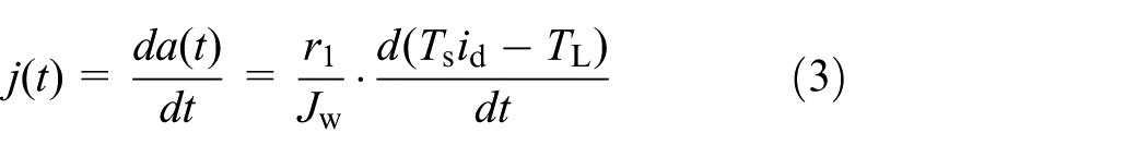
where a is the longitudinal acceleration, r1 represents the rolling radius of the wheel, Jw denotes the equivalent moment of inertia of the vehicle, id is the gear ratio of the final drive, and TL represents the vehicle load torque. A larger shift force will result in a major variation of rotational speed during the ascent stage of the synchronization process, and as a result the jerk increases. Hence, it is necessary to limit the rising velocity of the shift force at the beginning of the synchronization process.
Free movement to the target gear
Before the third phase, an axial force is necessary to rotate the synchronizer ring so that the spline chamfers of the sleeve and the synchronizer ring will be out of contact. The rotary force needed is described as

where r2 is the spline mean radius, Tloss represents the power losses, fs is the spline chamfer friction coefficient of the synchronizer ring, ε is the target gear angular acceleration, and β represents the spline chamfer angle.
When the synchronizer ring stops rotating, the sleeve continues to move toward the target gear until the contact of spline chamfers. 24 There are three kinds of possibilities of the relative position of the spline teeth. Figure 5 shows the three possible positions of the sleeve which are hard to detect and distinguish during the gearshift process. Hence, proper shift force should be applied in the controller to avoid crash during this phase.

Three possibilities of the relative position of the sleeve and the target gear.
Final gear mesh phase
The final phase needs to rotate the target gear if the final location of the sleeve is position 1 or position 2, while it is easy for the sleeve to move forward axially and mesh the splines of the gear where position 3 happens. It is better to apply a high force to start the second bump and turn the gear to finish the final mesh. 26 The second bump equation is

where mg is the mass of the gearshift mechanisms, asb is the axial acceleration of the gearshift mechanisms, and FN represents the force that acted on the chamfer surface.
The necessary axial force which is designed to rotate the synchronizer ring is described as

where ft is the spline chamfer friction coefficient of the target gear cone.
Similarly, the control requirement for the fourth phase is the fast motion control without crash. It can be concluded that the motion control influences the gearshift performance and shift force is the key factor. In accordance with the analysis above, the simulation model of the shift force for the four phases has been built, and the simulation results have guiding significance to the control method design. 23
Ideal kinetic characteristics
According to the detailed analysis, ideal displacement curve and moving speed of the ELA during a gearshift event can be designed and are shown in Figure 6. I, II, III, and IV represent the four phases, respectively. The maximum speed of each phase is variable according to the different gear and speed differences. The moving speed is limited by the shift force. A larger shift force is convenient to reduce the synchronization time, but the downtrend of the synchronization time becomes inconspicuous when the shift force is larger than a certain value. 25 Hence, it is inappropriate or unnecessary to implement an extremely large shift force which leads to abrasion, crash, and jerk when the speed difference is low. In consideration of the present gearshift time of electric AMT, less than 200 ms is set as the target gearshift time for the novel gearshift system according to the consideration of performance balance and control difficulty.

The ideal displacement and moving speed curves of the ELA.
Gearshift controller design
According to the analysis in the third part, three phases of the total gear engagement process are point-to-point movement. As a result, the gearshift controller should accomplish the gearshift process as fast as possible, while other shift performance indexes are in an acceptable range. Besides, the ELAs connect the shift fork rigidly without any intermediate mechanisms which means that the output force drives the shift fork directly. Hence, any abnormal output force will be transferred to the synchronizer directly which might cause an unpredictable phenomenon. Similarly, any vibration and impact produced in the transmission or clutch will be transmitted to the synchronizer too. All of these uncertainties will affect the gearshift performance. Therefore, robustness of the controller should be considered seriously.
Before the controller design, the mathematical equations describing the gearshift system are as follows 24

where vs is the moving speed of the sleeve, S denotes the displacement, and c represents the viscous friction damping coefficient. The state variables can be defined as

As a result, the state equation is described as

The system output variable is

From equations (7)–(9), it is easy to find that U is the input variable and I and vs are the intermediate variables which determine the values of shift force and displacement, respectively. Usually, a displacement closed-loop controller can satisfy the basic control requirements. Current closed loop is added to optimize the control performance due to the complex and variable working conditions.
The proportional–integral–derivative (PID) method is widely used in motion control, and it can achieve good displacement control accuracy. However, the PID method has no ability to restrain disturbances such as force fluctuations and shaft vibrations. Recently, the sliding mode control (SMC) method is extensively adopted to restrain inner parameter variations and outer disturbances. 28 Nonetheless, a poorly designed SMC controller will induce chattering and undesirable results. In addition, the linear quadratic regulator (LQR) control scheme is usually adopted to reduce the effect of disturbances and variations, 29 and they should be optimized to realize fast, stable, and high precision motion control.
The active disturbance rejection control (ADRC) method is proposed in recent years. The special characteristics of the ADRC method are that it treats all the influence factors including chattering of synchronizer components, shaft vibration, shift force fluctuation, and other uncertainties as disturbances 30 and it is applicable to the direct-drive electromagnetic gearshift system since there are vibrations, crashes, parameter variations, and uncertainties during the gearshift process. Hence, it is adopted to achieve stable, robust, consistent, and precise gearshift performance in this work. ADRC consists of a nonlinear state error feedback (NLSEF) law, a tracking differentiator (TD), and an extended state observer (ESO). 30 Figure 7 shows the basic topology of the ADRC.

Basic topology of the ADRC.
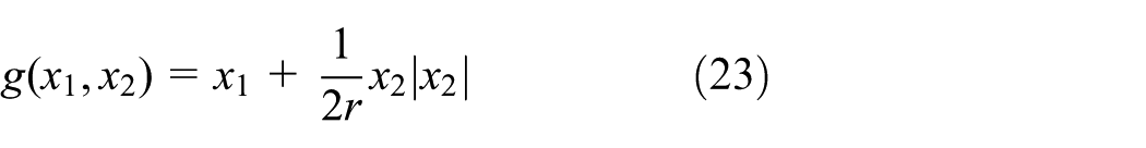
The function of TD is to produce a transitional trajectory v1 according to the variation of signal v so that the transient response is improved. 23 The typical form of TD is usually described as

and h is the sampling period. The function

The parameter r influences the dynamic response of v1, and the larger value of r will shorten the time which is taken by v1 of a specific v. 25
The ESO module can estimate the disturbances according to the analysis of output variables, and the estimation results are compensation to the target variable. As a result, the effect of disturbances is neutralized. The discrete-time form of the ESO module is 30
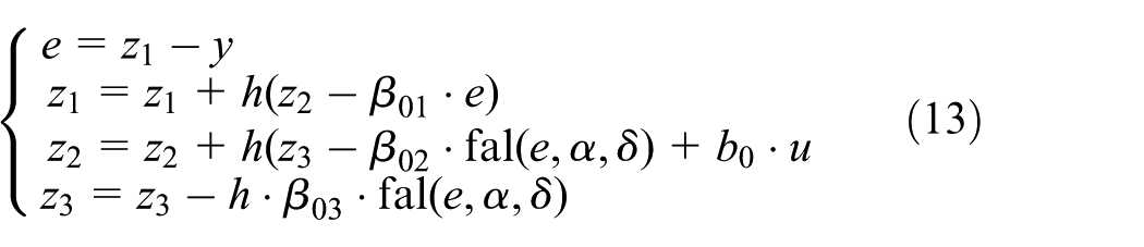
where z1, z2, and z3 are the estimated values of the variable y and any disturbances; β01, β02, and β03 are the observer gains and are usually selected as

where α satisfies α < 1, δ = kp·h, and kp is a positive integer. 30
The function of NLSEF is to generate the intermediate input variable u0 and is described as

where β11 and β12 are the control parameters and α1 and α2 satisfy the condition 0 < α1 < 1 < α231
ADRC is usually adopted to improve the robustness of the controller and is not good at fast motion control. Therefore, the ADRC method should be optimized to fit the control requirements described in the third section. The time optimal (TO) method is a kind of the optimal control method and the implementation of the TO method is to reach the target value using the least time which is quite appropriate for gearshift control.
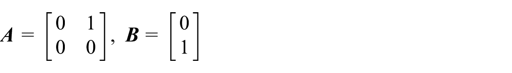
Considering the following second-order quadratic integral system
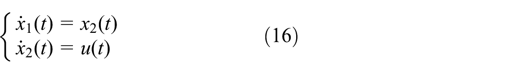
suppose
and equation (16) can be transferred into

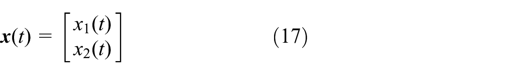
where
The original state

The constraint condition is

The performance index is

As a result, the control problem of the quadratic integral system is seeking the optimal input u*(t) to ensure that the controlled system moves from the original state to the final state, while the performance index J is the minimum. The typical control law u*(t) is given as 32

where
From equations (22) and (23), it is obvious that the optimal control law u*(t) is decided by the state variables x1 and x2, and as a result it can be realized by state feedback control. Since the actual value of u*(t) is the boundary value r or –r, and it changes from one boundary value to another, the TO method is a typical example of Bang–Bang control.
According to the second-order quadratic integral system as shown in equation (16), the displacement S and moving speed v are chosen as the state variables x1 = S and x2 = v. Since the gearshift process is divided into four phases, there are four different target values of x1 and x2. Taking the first stage as the example, the final value of the state variable is (x1, x2) = (xF, 0). Typically, the linear dynamic equation of the TO input is
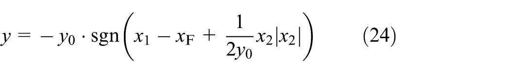
where xF is the desired target, y0 is the limitation of the input parameter y, and the sign function sgn is defined as follows 33

where

Hence, the TO motion control can finally be transformed into

Obviously, the TO controller needs the feedback of the output parameter x1 and its differential value

where k is the sampling time; z11, z12, z13, z21, and z22 are the estimation values; β01;, β02, β03, β11, β12, and δ are the parameters of the module ESO; u0 is the transition variable; and u1 is the practical input variable. The equation of u1 is changed which is convenient for the adjustment of the parameter b1.
From the above equations, it is concluded that a second-order control system is necessary to fulfill the precise control of displacement S. A closed loop of displacement is in charge of precise displacement control, and a closed loop of current can eliminate most of the disturbances. As a result, the TO-ADRC method for high precision and robustness is designed as shown in Figure 8.

The robust, precise, and fast motion control scheme.
Comparative simulations are necessary to verify the effectiveness of the designed control method. The PID method is widely used in motion control and was used in the previous work. Comparative simulations between the PID and TO-ADRC methods are carried out. Moreover, in order to examine the parameter adaptability of the three controllers, two kinds of different target displacement are given as 4 and 2.5 mm which, respectively, match the first and third phases of the gearshift process exactly. All of the simulations are carried out with MATLAB/Simulink models. Table 1 lists the determined values of the control parameters.
Typical parameter values of the controller.

Figure 9 shows the displacement response curves of the three controllers, and the desired value of S is set at 4 mm. It is obvious that the ADRC and TO-ADRC controllers reach the target displacement 4 mm with less time. The accurate times of TO-ADRC, ADRC, and PID are 14.5, 17.5, and 20.7 ms, respectively. In addition, the overshoot displacement response curve is also presented in Figure 9. The overshoot PID control can realize a similar response time with the TO-ADRC controller. However, the overshoot phenomenon is unacceptable. Besides, the response curve generates slight displacement oscillation due to the unadjusted PID control parameters.
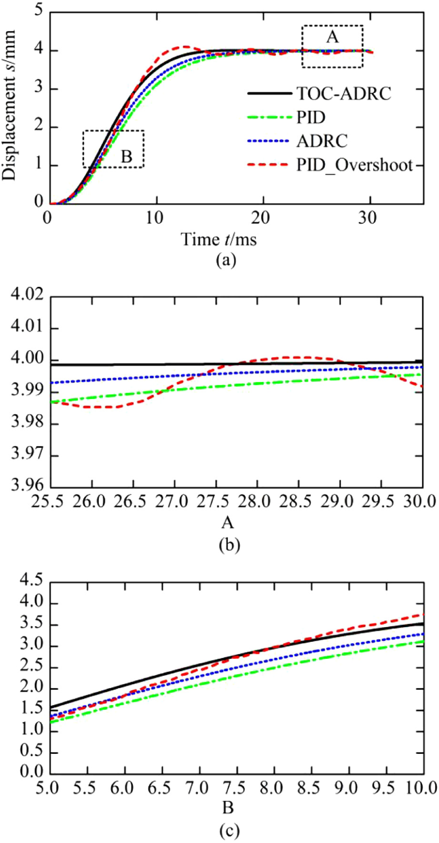
Displacement dynamic response comparison of the three controllers (4 mm): (a) displacement curve, (b) enlarged view of A and (c) enlarged view of B.
Parameter adaptability is an important characteristic of a robust controller. The displacement curve is shown in Figure 10 when the S value is 2.5 mm, while the parameters of the controllers remain unchanged. Obviously, different responses are presented due to the change of S which means different robustness to parameter variations. The variation of S has no influence on the displacement control with the TO-ADRC or ADRC controller. On the contrary, the PID method is affected by the variation. Overshoot and displacement oscillation is generated distinctly.

Displacement dynamic response comparison of the three controllers (2.5 mm): (a) displacement curve and (b) enlarged view of A.
Meanwhile, Figure 11 shows the displacement curves when the coil resistance changes. Compared with the other two controllers, the proportion of displacement change at 11 ms is 9.6% which is larger than those of TO-ADRC (1.3%) and ADRC (1.4%). Hence, it is concluded that the TO-ADRC and ADRC controllers have better adaptive ability than the PID controller. One of the distinct advantages of the ADRC method is that its robustness does not rely on the particularly accurate determination of control parameters which is convenient for the parameter setting. 23
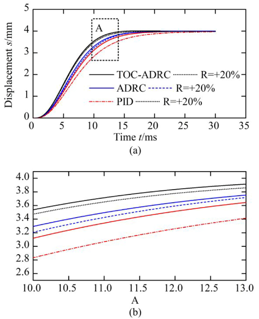
Displacement dynamic response comparison with coil resistance variation: (a) displacement curve and (b) enlarged view of A.
External disturbances exist frequently during the gearshift process, and they will influence the accuracy of motion control. An external disturbing force (20 N) is added as an extra friction force at 11 ms. As shown in Figure 12, the TO-ADRC and ADRC controllers have smaller fluctuations compared with the PID controller.

Displacement dynamic response comparison with external disturbance.
According to the comparative simulation results, it can be concluded that the TO-ADRC controller achieves the faster displacement response, and its perfect robustness is beneficial to improve the gearshift performance.
Experimental results
Test bench
The connection between the ELAs and transmission is shown in Figure 2. The transmission parts are the same as a common AMT except the actuators. The whole gearshift test bench equipped with two ELAs is shown in Figure 13. It comprises an intermediate-shaft AMT, an induction motor, two torque and speed sensors, two ELAs, and a flywheel. The input speed is supplied by the induction motor, and the vehicle inertia is simulated by the flywheel. Besides, the control system scheme is presented in Figure 14. An ARM cortex-M0 chip NM1330 is selected as the controller. The sensor signals are processed by the analog-to-digital converter (ADC) module and all of the data are transmitted to a PC through RS232. The two ELAs are driven by the pulse width modulation (PWM) module.

Gearshift test bench.
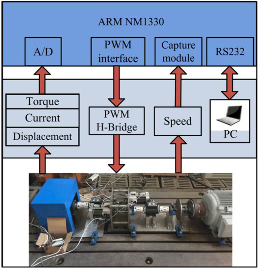
The control system scheme.
Experimental results of displacement dynamic response
Before the gearshift experiments, ELA motion control with the TO-ADRC and PID methods is carried out, respectively, when it is not mounted on the test bench. Comparative results between the simulation and experiment are presented in Figure 15. Meanwhile, two important performance indexes, namely, displacement error ed and response time td, are presented in Table 2. Due to the model accuracy and other uncertainties, the experimental results are inferior to the simulation results. However, the TO-ADRC method helps the ELA reach the target displacement faster than the PID method due to the TO module. Both of the control methods can acquire precise displacement when the target displacement is 4 mm, and the displacement error is very tiny which is acceptable. More crucially, the motion control performance of the TO-ADRC method remains stable when the target value is 2.5 mm, while overshoot and vibration are produced with the PID control method. Hence, there is no need to adjust the control parameters of the TO-ADRC method through the entire gearshift process, while the PID method needs to set three different kinds of parameter combinations. The simulation and experimental results of displacement response control reveal the fast dynamic response of the TO-ADRC method and its robustness to parameter variations.
Performance comparison of the TO-ADRC and PID methods.
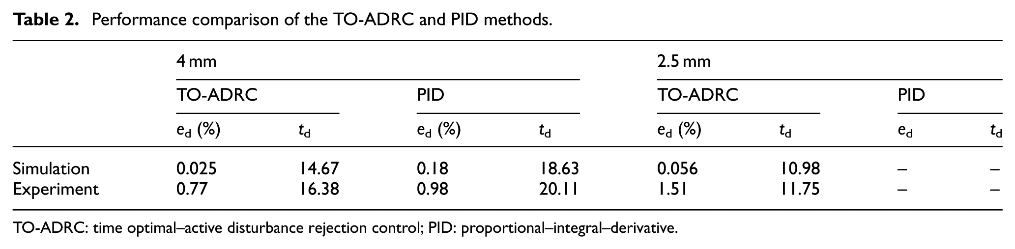
TO-ADRC: time optimal–active disturbance rejection control; PID: proportional–integral–derivative.

Displacement dynamic response with two different controllers: (a) the PID method and (b) TO-ADRC method.
Gearshift experiment results
Two kinds of different speed differences Δω 380 and 600 r/min are selected to carry out the gearshift events. Besides, the comparison experiments between the PID and TO-ADRC methods are carried out, respectively. All the experimental results are shown in Figures 16 and 17, and the specific index values are listed in Table 3.
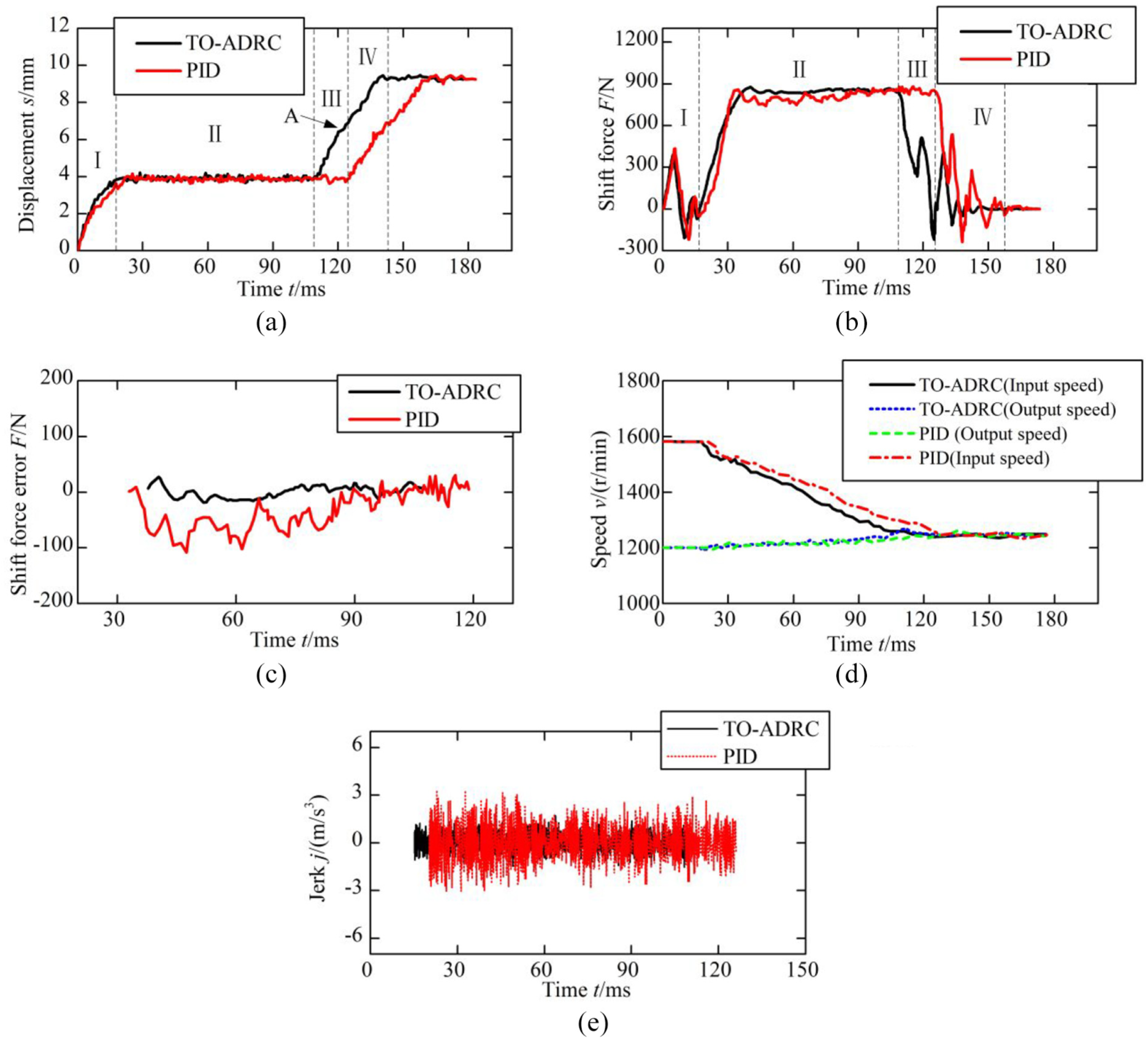
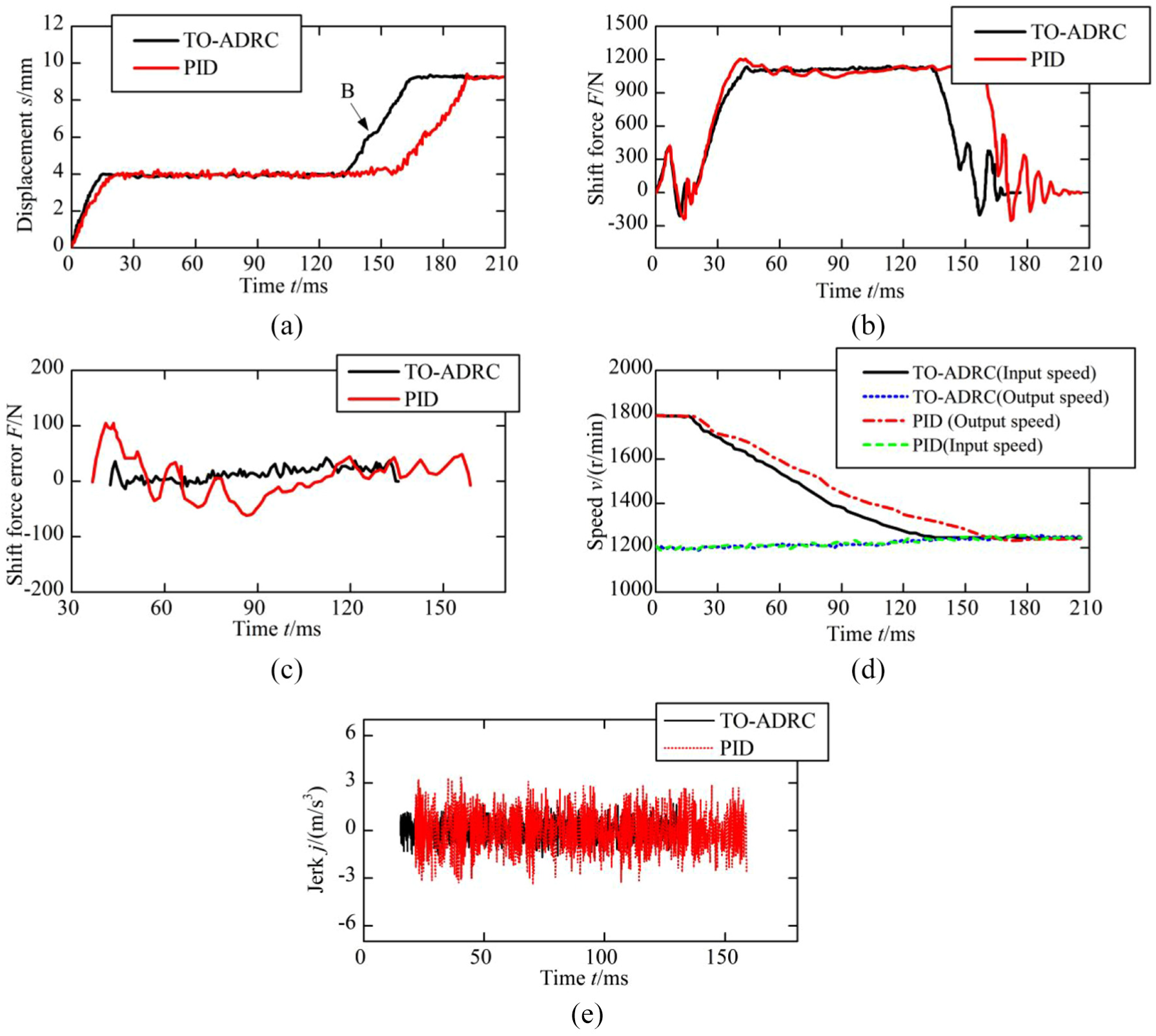
Gearshift experiment results (380 r/min): (a) displacement, (b) shift force, (c) shift force error of the synchronization process, (d) speed matching process, and (e) jerk.
Gearshift experiment results (600 r/min): (a) displacement, (b) shift force, (c) shift force error of the synchronization process, (d) speed matching process, and (e) jerk.
Comparison of performance indexes.

TO-ADRC: time optimal–active disturbance rejection control; PID: proportional–integral–derivative.
Figure 16(a) shows the comparison of displacement variation of the gearshift process when Δω is 380 r/min. Four phases are labeled I, II, III, and IV in Figure 16(a) and (b), respectively. The target displacement from the neutral position to the target gear is 9.3 mm, and the first phase is 4 mm. As shown in Table 3, the TO-ADRC method achieves a shorter time than the PID method. The reduced time is 23.8 and 29.7 ms when Δω is 380 and 600 r/min, respectively. In addition, label A in Figure 16(a) and label B in Figure 17(a) show different displacement curves of the third phase when different locations of the sleeve happen which are presented in Figure 7. Due to the crash of the spline teeth of the sleeve and the target gear, the displacement curve becomes flat for a moment before the start of the fourth phase.
The ADRC method is good at improving the robustness of the target system. Hence, it is obvious that the TO part shortens the shift time which matches the simulation results well. Taking Figure 16(a) as the example, the TO-ADRC method uses 16.8 ms to reach the target displacement 4 mm, while the time is 22.1 ms for the PID method. After the synchronization process, the TO-ADRC method takes 31.1 ms to finish the shift process, while the time is 39.3 ms for the PID method. The TO-ADRC method saves 13.5 ms from the above two phases. The saved time equals 12.4 ms when Δω is 600 r/min. As a result, the experiments prove the effectiveness of the TO method in improving the dynamic response of the gearshift system.
In addition, Figures 16(c) and 17(c) show the shift force error of the synchronization phase. It is clear that the PID method produces greater fluctuation during the synchronization process. The fluctuation ranges are (30 N, –108 N) and (104.8 N, –61.6 N) for the PID method when the speed difference values are 380 and 600 r/min, respectively, and decrease to (27.6 N,–18.8 N) and (35.6 N, –13.6 N) when the TO-ADRC method is implemented. Due to the stability of the control method, the TO-ADRC method takes 10 ms less than the PID method to accomplish the synchronization process when the speed difference is 380 r/min, and the value is 17 ms when Δω is 600 r/min. The robustness of the ADRC method plays an important role in obtaining better performance. Figures 16(d) and 17(d) show the speed matching curves.
Another important performance index is the jerk produced by the shift force fluctuation during the synchronization process. The calculated results are presented in Figures 16(e) and 17(e). The jerk can be caused by many factors such as torque fluctuations, speed variations, vibrations, and external disturbances. The maximum jerk usually happens during the ascent stage of the synchronization phase due to the fast increase of shift force. The rising slopes of the shift force presented in Figures 16(b) and 17(b) indicate that the PID method produces a larger jerk. The maximum jerk of the PID method is 3.4 m/s 3 and is significantly larger than that of the TO-ADRC method when Δω is 600 r/min. The experimental results reveal the better robustness of the TO-ADRC method.
Moreover, repeatability of the experimental results is another key indicator of a controller. 50 times of gearshift events are carried out and the variations of the performance indexes are presented in Figure 18. The shift time fluctuates from 132.1 to 146 ms, but most of them are around 140 ms. Similarly, the synchronization times stabilize around 90 ms. The fluctuations of jerk index are between 1.14 and 2.04 m/s 3 . Nonetheless, it has obtained a conspicuous progress compared with the PID method and the values are acceptable.

Repeatability experiment results.
Conclusion
A newly designed ELA-based AMT electromagnetic gearshift system is introduced. Two ELAs are adopted to carry out the gearshift events. Compared with the traditional AMT gearshift system, the novel gearshift system eliminates most of the intermediate mechanical devices and motion converter which are necessary for DC motor drive. Hence, the gearshift structure is simplified, and both the dynamic characteristics and mechanical efficiency are improved. The control requirements are confirmed through the detailed analysis of the gearshift process. The ADRC method is adopted to deal with complex working conditions and uncertain disturbances during the gearshift process. Besides, the ADRC controller is optimized with the TO method to pursue faster dynamic performance of the novel gearshift system. Comparative simulation and experimental results among the TO-ADRC, ADRC, and PID methods are presented. The superiorities of the novel gearshift system and the remarkable improvements of the adoption of the TO-ADRC method are demonstrated through comparison simulations and experiments. Further investigations will focus on coordination control of the two ELAs so that gearshift time can be shortened or even eliminated.
Footnotes
Handling Editor: Yanjun Huang
Declaration of conflicting interests
The author(s) declared no potential conflicts of interest with respect to the research, authorship, and/or publication of this article.
Funding
The author(s) disclosed receipt of the following financial support for the research, authorship, and/or publication of this article: This work was supported by Taizhou Science and Technology Planning Project (Grant No. 162gy51), General Scientific Research Project of the Zhejiang Province Education Department (Grant No. Y201636677), and National Natural Science Foundation of China (Grant No. 51505263).