
Abstract
The bogie 6-degree-of-freedom dynamic simulation test bench can simulate various operating conditions of the bogie through coordinated movement of the three parallel 6-degree-of-freedom motion platforms; however, the motion of the platforms will be interfered by some space obstacles. In order to obtain the collision-free workspace of the 6-degree-of-freedom motion platforms, a limit boundary–search method based on the collision-detection model is proposed. The structure of three parallel 6-degree-of-freedom motion platforms is analyzed, and its inverse kinematics model is established. Considering its internal constraints, the constraint models of the actuators’ stroke and the spherical hinges angle are established. Based on the collision-detection method between convex polygons, the minimum distance-detection models between platforms and obstacles as well as between actuators and obstacles are established. Then the limit boundary–search method is used to search for all boundary points that satisfy the constraint conditions. Finally, the correctness and feasibility of the proposed method and models are verified by some simulation examples. The proposed research avoids collisions effectively and provides a reference for the optimal design of the test bench.
Keywords
Introduction
Workspace analysis plays a significant role for parallel mechanisms. The shape, size, and volume of the workspace of the mechanism are limited by many factors.1–2 For a long time, many scholars have performed extensive research on determining the workspace of parallel mechanisms.3–4 In recent years, the research on the workspace characteristics of various parallel robots has become a hot topic. 5
The workspace of a parallel robot is mainly solved by the graphical, 6 analytical, 7 and numerical methods. 8 For examples, Abdel-Malek et al. 9 obtained the workspace of the tandem-type manipulator by using the quadric surface. Liu et al. 10 obtained the boundary point of the robot’s workspace using the Monte Carlo method. Castelli et al. 11 proposed a boundary-computation algorithm based on the binary representations of the manipulator workspaces. Bohigas et al. 12 introduced the method of determining the workspace boundary of general structural manipulator. Furthermore, the limit boundary–search method 13 is a representative numerical method and is applied more in practice, for examples, Zhang et al. 14 obtained the workspace of the seed implantation robot for prostate tumors by the limit boundary–search method. Zhang et al. 15 obtained the workspace of a 6-prismatic-spherical-spherical (PSS) parallel machine tool by solving the limit value of the constraint condition. However, most studies only consider the influence of internal factors on their workspace and seldom consider the influence of external obstacles. Therefore, to avoid collisions and improve efficiency, some scholars have begun to study the collision-free workspace.16–18 A notable example is an obstacle-free workspace of the parallel mechanisms with an interval-based approach obtained Farzanehkaloorazi et al. 19
In this article, a bogie 6-degree-of-freedom (6-DOF) dynamic simulation test bench 20 was analyzed. It is a parallel mechanism composed of three 6-DOF motion platforms, there are 21 actuators to drive it. The test bench can simulate the motion pose of the bogie and complete the test of its performance parameters under various dynamic conditions. 21 For convenience, some mating devices were installed on the test bench, like the beginning and the intermediate transition platforms and the braced frames. Thus, the workspace of the 6-DOF motion platform is bound by many factors, such as telescopic stroke, spherical hinge angle, and the surrounding obstacles. Therefore, it is essential to explore the collision-free workspace of 6-DOF motion platform and establish the internal constraint and collision-detection models between mechanisms and obstacles.
At present, two well-known collision-detection algorithms to calculate the minimum distance between convex bodies are Lin–Canny (LC) algorithm 22 and Gilbert–Johnson–Keerthi (GJK) algorithm. 23 In order to optimize and improve the efficiency of detection, many scholars have carried out further research. Li et al. 24 proposed the projection separation surface method to achieve collision detection by constructing a quasi-projective separation surface. Zhang et al. 25 proposed a real-time collision-detection algorithm with a ridge-projection separation for convex polyhedrons. Jin et al. 26 proposed an algorithm to calculate the shortest distance between the static–static convex bodies, which could judge whether two objects collide or not. By means of the above algorithms, the problem of collision between static–static convex bodies can be solved. However, given that the actuators, platforms, and obstacles all belong to a convex body and the actuators also belong to a variable-size convex body, it is still necessary to solve the problem of collision between the moving and static objects.
This article proposed a limit boundary–search method to solve a collision-free workspace of the bogie 6-DOF dynamic simulation test bench. The inverse kinematics model of the 6-DOF motion platforms were established by the kinematics analysis. The interference models of the workspace of the test bench, such as the constraint models of the actuators’ stroke and the spherical hinges angle, the distance-detection model between vertical actuators of the upper platform and obstacles, as well as the distance-detection model between the vertical actuators of the lower platform and obstacles, were established. Based on the built models, the steps to solve the workspace by the limit boundary–search method were given. The results via the simulation runs reveal that it is feasible when used to solve the workspace of the mechanism.
Kinematics analysis
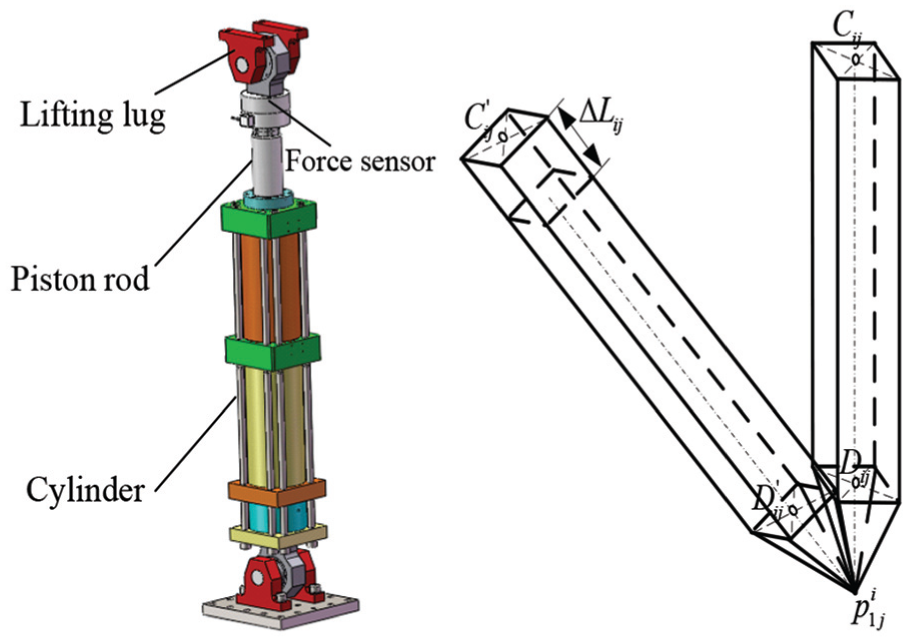
As shown in Figure 1, the bogie 6-DOF dynamic simulation test bench mainly includes three 6-DOF motion platforms, a mechanical frame, an electro-hydraulic vibration system, a bogie ferry assembly, and so on. The upper 6-DOF motion platform installed on the mechanical frame is used to load on the bogie, and the two lower 6-DOF motion platforms installed on the foundation are used to simulate the road condition of bogie operation. Every 6-DOF motion platform is driven by seven actuators, and each actuator is connected to the platform by a spherical joint.

Overall structure of bogie dynamic simulation test bench.
For convenience, the local coordinate system was introduced into the kinematic analysis 27 of the test bench. The intersection of the transverse and vertical symmetrical section of the upper 6-DOF motion platform projected at the horizontal plane was selected as the origin of the global coordinate system. The global coordinate system O-XYZ was established, and its x, y, and z axes were the longitudinal direction, the transverse motion direction, and the vertical motion direction of the train, respectively. Next, three local coordinate systems were established. The directions of the x, y, and z axes of the local coordinate systems are as same as the global coordinate system, and the origins of the three local coordinate systems are shown in Figures 2 and 3.

Left view of 6-DOF motion simulation platforms system.

Front view of 6-DOF motion simulation platforms system.
The three 6-DOF motion platforms of the test bench have the same structure, and their pose inverse solution models are similar. Therefore, kinematic analysis was performed by taking the upper platform as an example. According to its geometric structure parameters, the coordinate vector of the upper hinge points of actuators 1.1–1.7 in the local coordinate system can be expressed as follows

The coordinate vector of the lower hinge points of actuators 1.1–1.7 in the local coordinate system can be expressed as follows

The coordinate vector of the lower hinge points of actuators 1.1–1.7 in the global coordinate system was expressed as follows

where
The pose of the local coordinate system relative to the global coordinate system can be described as

where c and s denote cos and sin, respectively.
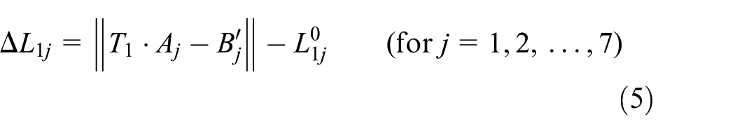
The expansion amount
Constraint factors of the workspace
Actuators’ expansion amount
The test bench realized the movement of the platforms by controlling the expansion of the actuators. The design range of the actuators’ stroke was constant due to the restriction of its mechanical structure. Therefore, the stroke of the actuator needs to meet the following length constraints

where,
In this article, the design range of all actuators’ expansion amount is
Spherical hinges’ angle
The working angle of spherical hinge at both ends of the actuator can only be within a certain range because of its structural characteristics. The geometric structure of the spherical hinge is shown as Figure 4. The workspace of the spherical hinge is a cone with the center of the spherical hinge as the apex. Its axial maximum swing angle along the shaft pin is

Geometric model and structural sketch of the spherical hinge: (a) geometric model and (b) structural sketch.
With one of the actuators as an example, it is known that the distance between the center point of the lower spherical hinge and the borderline of the hinged support is Ls = 65 mm; the distance between the center line of the lower spherical hinge and the inner side of the hinge support is Lv = 72 mm; and the width of the spherical hinge connecting rod is D = 80 mm; then the maximum rotation angle of spherical hinge is
As shown in Figure 5, it is assumed that

where i expresses numbers of the three moving platforms; j expresses the numbers of the seven actuators;
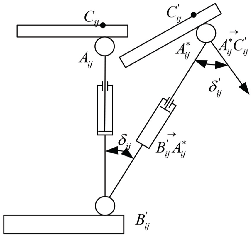
Angle diagram of the spherical hinge.
The initial vector between the upper and the lower hinge point can be expressed as

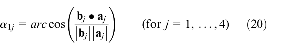
According to the angle theorem of space vector, the included angle
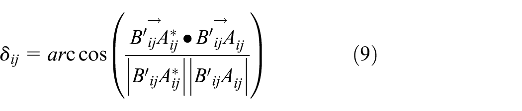
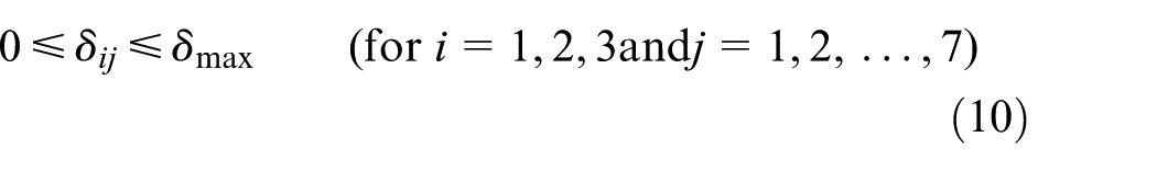
Then the lower spherical hinge should satisfy the constraint condition as follows
During the movement of the platform, the upper spherical hinge support is always vertical to the upper platform. As shown in Figure 5, it is assumed that

Then the upper spherical hinge should satisfy the constraint condition as follows

Interference between platforms and obstacles
In order to ensure that the test bogie or test vehicle can be pushed into the test station, the transition device has been designed. It includes the beginning and the intermediate transition platforms that can move along the longitudinal direction and the intermediate support platform with the guide rails, as shown in Figure 6. If the amplitude of the side roll and translation of the moving platform exceed the space limit, the motion platforms and the transition device may have interference problems.

Structural model of the lower platforms and the transition device.
Therefore, in order to avoid collisions in the process of movement, the minimum distance between platforms and obstacles should be greater than zero at any time. This can be obtained by using the algorithm for calculating the shortest distance between convex polyhedrons in article. 26
From the perspective of space mathematics, if both points

In general, a spatial convex polyhedron can be represented by a convex combination of convex polyhedral vertices. If the convex polyhedral vertex set is
In this article, the intermediate transition platform is simplified as the convex polyhedron U with eight vertices. Supposing that

For the beginning transition platform which is simplified as the convex polyhedron S, supposing that

For the intermediate support platform which is simplified as the convex polyhedron E, supposing that

For computational convenience, the platform i is simplified to the union of three convex hexahedrons, as shown in Figure 7. The three convex hexahedrons of platform i are represented as

where Ti is the homogeneous transformation matrix of the platform i in rotation space,

Split model of the platform i.
Therefore, the distance-detection models between the platform 2 and the intermediate transition platform with the intermediate support platform, respectively, can be expressed as follows

The distance-detection model between the platform 3 and the beginning transition platform can be expressed as follows

When the platforms are moving, it is necessary to make sure the distances (
Interference between actuators and obstacles
As shown in Figure 6, there may be movement interference between the vertical actuator j of the lower motion simulation platform i and the intermediate support platform during exercise. In addition, the main crossbeam is large in size and complex in structure, so it is easy to cause movement interference between the main crossbeam and the vertical actuator j of the upper platform, as shown in Figure 8.

Position between the vertical actuators and main crossbeam.
Therefore, in order to avoid collisions in the movement, the minimum distance between actuators and obstacles should be greater than zero at any time. Based on the algorithm for calculating the minimum distance between convex polyhedrons, the distance-detection model between the vertical actuators of the upper platform and obstacles, as well as the distance-detection model between the lower platforms and obstacles, are established.
The distance-detection model between the vertical actuators of the upper platform and obstacles
In this article, we ignored the geometrical characteristics which have no influence on the collision and simplified the actuator as a simple polyhedron with nine vertices. As shown in Figure 9, this polyhedron’s upper vertex stands for the origin of the upper spherical hinge, which can be represented by the point
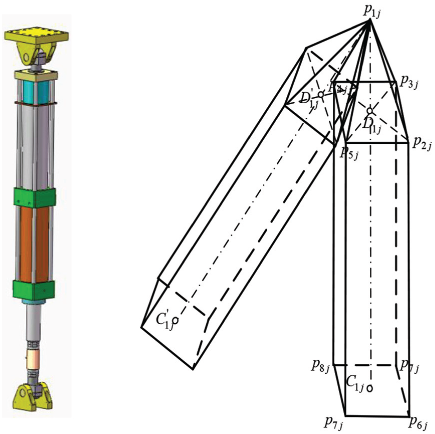
Kinematic simplified model of vertical actuator j of the upper platform.
Supposing the initial vector between the upper and lower hinge points of actuator j is
Thus, the following relationship can exist
where
The first component
1. When
For the first case, the axis after motion is in the YOZ plane; then, according to the trigonometric function and the circular motion characteristic, the coordinate of intersection point
where
Therefore, the coordinate of the vertices

where

In the same way, the coordinates of
2. When
The vector between point

The distance between point

The coordinate of intersection point

where
Since the point

When
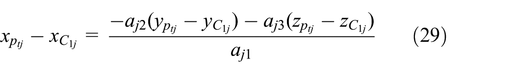
The distance formula between point
Therefore, the coordinate of the vertices

where
where
In the same way, the coordinates of
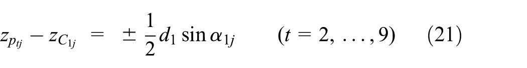
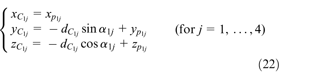
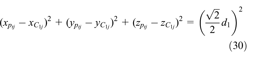
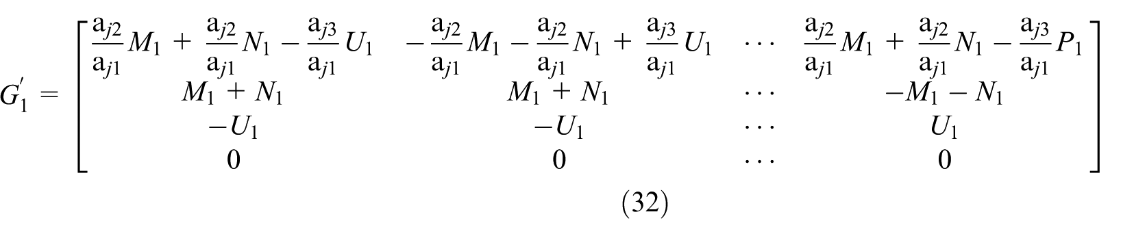
In summary, the spatial mathematical representation of the vertices in the global coordinate system can be obtained by formulas (22)–(32). Supposing that

Supposing that

Therefore, the distance-detection model between the vertical actuator j of the upper platform and the crossbeam can be expressed as follows
The distance-detection model between the vertical actuators of the lower platform and obstacles
As shown in Figure 10, we simplified the vertical actuator of the lower platform as a convex polyhedron with nine vertices, the polyhedron’s lower vertex stands for the origin of the lower spherical hinge, which can be represented by

Vertical actuator’s kinematic simplified model of the lower platform.
According to formulas (5) and (36), we can know the distance

where
The coordinates of the vertices

Supposing that

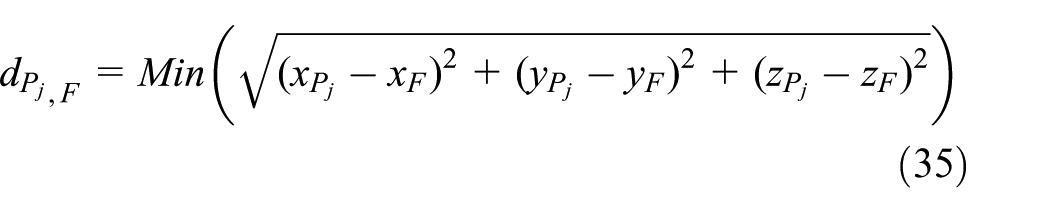
Therefore, the distance-detection model between the vertical actuator j of the lower platform i and the intermediate support platform can be expressed as follows

In summary, in order to ensure that the actuators avoid the obstacles effectively,
Workspace analysis
Workspace search algorithm
According to the inverse kinematics model and structural parameters of the parallel motion platforms, all the constraint models can be calculated when the motion platform maintains a certain pose. If the results of the calculations satisfied all the constraint conditions, it can be judged that the position is within the workspace. Thus, if the boundary points on all sections can be searched, the workspace of the 6-DOF motion platform is exactly the space surrounded by these points.
The limit boundary–search method to solve the platform’s fixed pose workspace consists of the six steps as follows:
Step 1: Determine the initial position of the 6-DOF motion platform and give it a fixed pose
Step 2: According to the bar length constraint of the vertical actuators of the test bench, the lowest point
Step 3: The search space is divided into k differential spaces by using a planar cluster that is parallel to the XOY plane with a thickness about

Step 4: Each tiny subspace is treated as a section of the workspace, the polar coordinate search method is used to determine the workspace boundary of each section, throughout the search process, the polar angle

Step 5: The pose point searched from one section plane is substituted into the pose inverse solution model and the spatial mathematical model of the moving platforms; all the constraint models can be calculated. If the calculations satisfied all the constraint conditions, the point is included within the workspace.
Step 6: Record all the points satisfying step 5, and the space composed by these points is the collision-free workspace of the 6-DOF motion platform.
Simulation and analysis
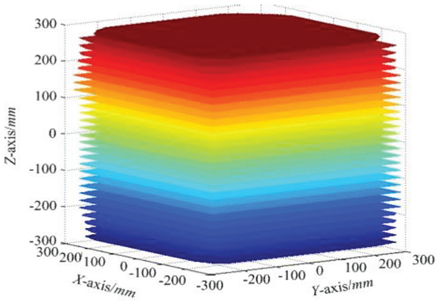
The fixed-pose workspace is the space formed by the translation quantity of the reference points along the x, y, and z axes, when the motion platform maintains a certain pose. Based on the inverse kinematics model and the various constraint conditions, the position workspace of platform i can be obtained with the limit boundary–search method. Factors affecting the workspace of platform 1 are the actuators’ expansion amount, the upper and lower hinge angles, and the minimum distance between the vertical actuator j and the crossbeam, then the positions in the workspace should satisfy the constraints of formulas (6), (10), (12), and (35), as shown in the following

It is known that the structural parameters of the upper platform and the crossbeam at the initial position. Then, the workspaces of platform 1 at the fixed pose

Position workspace of platform 1 at pose

Position workspace platform 1 at pose
In Figure 11, the searched result show that the workspace of the upper platform has the following features: (1) The fixed-pose workspace is approximated as a hexahedron with a trapezoidal cross-section, which conforms to the theory that the longer the radius, and the longer the trajectory. (2) The four vertical actuators are symmetrically distributed on both sides of the main crossbeam, so the entire fixed-pose workspace is symmetrical about the XOZ section and the YOZ section, respectively.
By comparing Figures 11 and 12, we can see that the platform 1 has maximum position workspace at pose
The factors affecting the workspace of the lower motion platforms are relatively complex. They include the actuators’ expansion amount, the upper and lower hinge angles, the beginning and the intermediate transition platforms, as well as the intermediate support platform. According to the constraint equations (6), (10), (12), (18), (19), and (40) described above, the workspace of platforms 2 and 3 at pose
Position workspace of platform 2 at pose

Position workspace of platform 3 at pose
Conclusion
This article presents a method for solving the collision-free workspace of the bogie 6-DOF dynamic simulation test bench. Through the kinematics analysis, the pose inverse solution model of the 6-DOF motion platform is established, which provides the basis for the further establishment of the motion constraint model and the minimum distance-detection model. Based on the collision-detection method between convex polygons, the minimum distance-detection models between platform and obstacles, as well as between actuators and obstacles are established, which can effectively prevent collisions. Based on all the models that have been built, the limit boundary–search method is introduced to solve the workspace of the 6-DOF platform, which lays the foundation for the optimal design of the motion platforms and the smooth progress of the bogie dynamic simulation test. The modeling method for variable-size object constrained by spherical hinge and the collision-detection model between dynamic and static polyhedrons has good reference for the spatial motion analysis and collision detection of other multi-degree-of-freedom mechanisms.
Footnotes
Handling Editor: Jose Ramon Serrano
Declaration of conflicting interests
The author(s) declared no potential conflicts of interest with respect to the research, authorship, and/or publication of this article.
Funding
The author(s) disclosed receipt of the following financial support for the research, authorship, and/or publication of this article: This work was financial supported by the National Science Foundation of China (NSFC) (grant no.: 51575232) and the National Science Foundation of Jilin Province, China (grant no.: R20160204018GX).