
Abstract
When a mechanical system fails, the most important thing is to find out the fault location and causes quickly and accurately. Based on the meta-action unit, this article proposes a comprehensive, qualitative, and quantitative fault diagnosis method composed of fault tree analysis and evidential network to analyze faults of the mechanical system. First, we expand the function–motion–action decomposition method, revise the definitions of meta-action and meta-action unit derived from the function–motion–action decomposition of the complex mechanical system, use the fault tree analysis approach to analyze the faults of the meta-action unit instead of the system directly, and establish the meta-action unit fault tree analysis (MU-FTA) model with simple levels. These activities can tremendously simplify the qualitative diagnostic model. Second, the MU-FTA model is mapped to the evidential network model according to their similarities. Finally, we fuse the after-sales data and expert experience information by Dempster’s combination rule to calculate the basic probability assignments of the parent nodes in the bottom layer of the evidential network model. Thus, the basic probability assignments of meta-action units are obtained by network transmission and the diagnostic conclusion is acquired. The fault diagnosis of a certain type of numerical control turntable is conducted as an example to demonstrate and verify the feasibility and effectiveness of the proposed approach.
Keywords
Introduction
A fault appears when the product cannot perform the required function. 1 The activities of fault diagnosis usually involve fault location, fault mode analysis, and fault reason analysis. With the development of high speed, high precision, high integration, and composition of items, their increasing functions and complicated structures are surging the difficulties of fault diagnosis.
Fault location and fault reason analysis are two important parts of the fault diagnostic activity. According to the survey, 2 when an item has failed, the time spent in seeking out the fault reason accounts for 80% and the rest for repairs. Hence, it is necessary to study how to locate the fault and find the fault cause quickly and accurately.
Many scholars have devoted themselves to seeking better fault diagnostic methods of products. At present, there are three main approaches: 3 signal-based approach,4,5 model-based approach,6,7 and data-driven approach.8–10 The signal-based approach is implemented by analyzing the monitored signal and extracting the feature information for fault diagnosis. The model-based approach can be categorized into qualitative and quantitative fault diagnostic approaches, and their difficulties are the construction of the diagnostic model of production with a complex structure. The data-driven approach requires a large amount of data including online monitoring data and historical data. The three methods have their own advantages and disadvantages. In order to help maintenance personnel find the fault location and fault causes, a novel hybrid fault diagnosis method including the fault tree analysis (FTA) and evidential network (EN) is proposed for the complex mechanical system of product in this article.
The FTA approach is a proven and effective fault analysis technology. Wang et al. 11 summarized the five fault types of power transformer and gave the four fault trees (FTs) of subsystems to diagnose power transformers. Hu et al. 12 proposed a layered diagnostic method of operational faults of the manufacturing system by the FTA approach and the other two diagnostic models based on logical control and sequence control, respectively. Hurdle et al. 13 conducted the FTA approach in diagnosing the sophisticate system to explain the deviations from normal operations observed in sensor outputs. In Fazlollahtabar and Niaki, 14 faults of key parts of industrial robots were analyzed by the FTA method and thus the reliability of the system was solved by the minimum path method. Peeters et al. 15 proposed a high-efficiency fault analysis method uniting FTA with the failure mode and effects analysis (FMEA) in a recursive way. For the product with a complex mechanical system the traditional FTA method has some deficiencies such as difficult modeling, enormous model, and time-consuming solution. This article uses the function–motion–action (FMA) decomposition method to improve the weakness of the traditional FTA approach.
The FMA decomposition method proposed by Prof. Zhang 16 from Chongqing University and his colleagues is a decomposition method based on the function of mechanical products. It has three steps: the analysis of the product to obtain the functions, the function decomposition to obtain the motions, and the motion decomposition to obtain the meta-actions. Recently, the approach is mainly applied for the reliability analysis of computer numerical control (CNC) machine tools. Li et al.17,18 conducted the assembly reliability modeling technology of CNC machine tools and proposed an error transfer model of CNC machine tools based on meta-action assembly unit (MAU) by analyzing five kinds of error sources. Ran et al. 19 addressed the quality characteristic allocation technology of CNC machine tools based on MAU. In the above studies, the FMA decomposition method is an effective method of processing the reliability of complex mechanical products. It can decompose the complex mechanical products into a battery of meta-action units (MUs) with clear and simple structures. In the meantime, functions of complex mechanical products are realized by these MUs. This article uses the FMA decomposition method to obtain the MUs and then diagnoses them by the FTA method.
The meta-action unit fault tree analysis (MU-FTA) model can solve the difficulty of modeling by the traditional FTA approach and realize qualitative diagnosis of a sophisticated mechanical system. However, due to hazy information, data missing, and incomplete data, uncertainty problems exist in the quantitative diagnosis. 20 Although the fuzzy set theory 21 is a good way to deal with uncertainty problems, the membership function is hard to acquire. The Bayesian method 22 and the Dempster–Shafer (D-S) evidence theory are also two good approaches. The Bayesian method requires prior information of the hypothesis and the sample information to calculate the posterior information by Bayesian formula. Compared with the Bayesian method, the D-S evidence theory does not need prior information. Compared with the fuzzy set theory, it needs less data and can fuse multi-source information. Because of these advantages, in recent years, it is widely used in the information fusion,23,24 target recognition,25,26 and risk assessment27,28 areas. In this article, the data mainly from the after-sales data and expert experience information are discrete and insufficient, and therefore we use the D-S evidence theory to dispose the uncertainty in the quantitative diagnosis process.
The EN model proposed by Simon et al.29–31 is based on the Bayesian network (BN) model.32,33 Compared to the BN model, the EN model need not calculate the prior information and can handle information from different sources. The limitation of the EN model is that its data must be discrete. 34
The EN model can convey the uncertainty of each evidence well, while the construction of the network structure is a puzzle. Yang et al. 35 addressed some transformation relationships between the logical gates in the FTA approach and the equivalent EN and built the EN model to analyze the failure probability of some events in the early stage of product design without sufficient data. Based on the transformation relationships given by Simon and Yang, we construct the meta-action unit evidential network (MU-EN) model to analyze the fault of a complex mechanical system quantificationally. The abbreviations used in this article are shown in Table 1.
Abbreviations.

The proposed approach
The proposed approach includes four steps as shown in Figure 1. First, we use the FMA decomposition approach to decompose the complex mechanical system of product into a series of MUs. Second, we use the FTA approach to analyze the faults of MUs qualitatively. Third, based on the similarities between FT and EN, we map the MU-FTA model into the MU-EN model. Finally, using Dempster’s combination rule to combine the expert data and after-sales data, we obtain the basic probability assignments (BPAs) of the parent nodes in the MU-EN model. By propagating these BPAs through the EN, we obtain the BPAs of MUs and the diagnosis conclusion.

Flowchart of the proposed approach.
The FMA decomposition approach
The traditional reliability research approach of mechanical products adopts the “Product-Component-Part” decomposition method, which starts with decomposing the item into many components and then decomposes the components into parts to construct the reliability block diagram (RBD) model and the mathematical model in the component and part levels, respectively. Nevertheless, the mechanical product is assembled by a large number of parts including many non-standard parts, the failure data of which cannot be obtained through a large number of tests like electronic elements. So the reliability model in the part level is hard to build, whereas the model in the component level is very rough. In addition, the function and performance of the mechanical product are mainly implemented by the motions and interactions between different parts. If the interactions of parts are ignored, the established model will be inaccurate. Therefore, Zhang et al. 16 presented the FMA decomposition approach to study the reliability of mechanical products. Li 36 addressed a detailed discussion on the FMA decomposition approach and the concept of meta-action in her doctoral dissertation.
This article modifies Li’s FMA decomposition model. The top level of the FMA decomposition approach elaborated by Li is the whole machine/system level. This article expands it into the component/subsystem level because the mechanical fault sometimes manifests in the component /subsystem level, such as the no-action of the numerical control turret. Thus, the FMA decomposition approach should include the product function–motion–action (PFMA), system function–motion–action (SFMA), component function–motion–action (CFMA), and subsystem function–motion–action (SSFMA). The extended FMA decomposition approach is shown in Figure 2. Although we extend the product category, the application scope of the FMA decomposition method is only the mechanical systems of these products/systems.
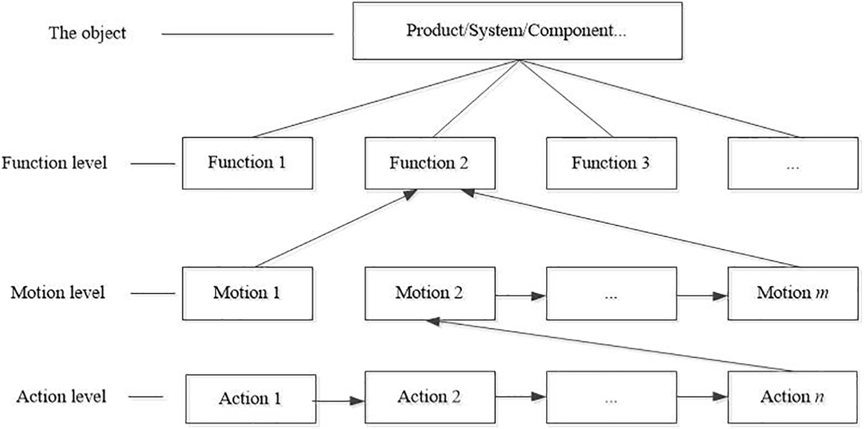
The modified FMA decomposition approach.
In Figure 2, the modified FMA decomposition approach has a four-layer structure. The first layer (top level) representing the object to be analyzed is the product/system/component/subsystem layer. The second layer (middle level) denoting the function decomposition of the object is the function layer. The third layer (middle level) decomposing the second layer from the view of motion is the motion layer including all motions to realize the function. In the third layer, we use the directed line to represent the relationship between motions, for example, the relationships of Motion 2∼m are in series and the relationship of Motion 1 and Motion 2∼m is in parallel. The fourth layer (bottom level) is the action layer representing all the actions called meta-actions to realize the motion. We also use the directed line to express the series relationship of the meta-actions.
Beginning with the function analysis, the FMA decomposition method can divide the object into a series of actions from the perspective of motion. Thus, reliability research of the object can be transformed into the study of these actions. Li 36 defined the action as meta-action that has the relatively independent controllable and analyzable structure, the ability to achieve a certain motion target or to achieve a certain goal and analysis, and cannot be decomposed into other actions.
Definition of MU
This article revises the definition of meta-action as the elementary mode of motion that can transmit the movement and momentum in the mechanical system. The revised definition includes three key points: the applicative range, the mode, and the effect of meta-action. The meta-action is used in the analysis of the mechanical system of the product. Its basic motions only include two types: the translation and the rotation. The effect of the meta-action is the transmission of the movement and momentum to realize the function.
From the view of the relationship between motion and structure, this article amends the definition of MU as the entirety of all parts in a stable structure to perform a meta-action. Figure 3 shows the basic model diagram of MU.

The basic model diagram of the meta-action unit.
In the dashed box shown in Figure 3, an MU contains five basic elements: the power input part, the middle part, the power output part, the strut member, and the fastener, the definitions and effects of which are shown in Table 2. The power source of MU can be a motor or the power output part of the last MU. Moreover, the directed lines starting from the power source and ending with the next MU express the flow direction of energy, force, and velocity among the different parts.
The definitions and effects of the basic elements of MU.

MU: meta-action unit.
When a mechanical system fault occurs, the process of fault location and fault reason analysis will be difficult due to the complex mechanical structure and the interactive relationships of the parts. To solve the problem, we decompose the mechanical system into a series of MUs by the modified FMA decomposition method. As the basic motion elements of the mechanical system, these MUs can transmit movement, force, and energy. Since the MUs have their own quality characteristics related to the function and performance of the mechanical system, we can perform the fault analysis of the MUs to achieve fault diagnosis of the mechanical system. The MUs usually have only two basic types: translation MU and rotation MU. The fault diagnosis model of MU is very simple and efficient because of its simple structure. In addition, the fault analysis of MU can be carried out due to its following features:
Integrity. The MU has a complete structure so that it can deliver motion, energy, and so on. The MU with an incomplete structure cannot be diagnosed as a separate module because the comprehensiveness of results cannot be guaranteed due to the omissions, which will affect the diagnostic quality.
Independence. Every MU is a relatively independent action unit because it can accomplish the specified motion function. It means that each MU can be diagnosed independently, which will support simultaneous fault analysis on multiple MUs to improve the efficiency. Independence does not mean that each MU is isolated. When we consider the power source and the output of each MU, they are associated.
Minimality. At the bottom layer of the FMA decomposition model of the mechanical system, the meta-action is the smallest motion and cannot be decomposed continuously. Therefore, the MU is the minimum fault analysis unit of a mechanical system.
The integrity guarantees the comprehensiveness of fault analysis, the independence guarantees the high efficiency, and the minimality guarantees the accuracy.
The MU-FTA model
The FTA method based on the structure of the product is a mature and effective fault analysis method. The FT of a complex mechanical system, in general, has many middle layers between the top and the bottom layer, which results in a sophisticated and enormous diagnostic model. Therefore, this article proposes an MU-FTA model that applies the FTA method to the MU instead of the mechanical system directly.
First, when it is determined that a certain fault of the product is caused by the fault of the mechanical system, we decompose the mechanical system into a series of MUs by the FMA decomposition method. Then, the MU-FTA model is constructed by analyzing the five basic elements of every MU. Compared with the electronic product, the MUs are connected by mechanical fit, for instance, the worm wheel rotation MU and the worm rotation MU are jointed by the engagement of the worm wheel and the worm. Therefore, the fault reason of the fit clearance should be considered when constructing the FTs of the adjacent MUs. In order to avoid the problem that a fault cause may exist in the FTs of the two MUs, we stipulate that this type of failure cause is only considered in one MU.
The advantages of the MU-FTA model are as follows:
Fewer levels. The clear and concise structure of MU facilitates fine modeling and accurate analysis. Thus, the MU-FTA model with less intermediate layer events is simple.
Clear and concise logical relationship. Compared with the traditional FTA model, the logic relationships of the MU-FTA model usually include two logical relations: “AND gate” and “OR gate.” Hence, it is relatively simple and easy to find the fault cause.
High efficiency. Fault analysis of MUs can be performed in parallel, which greatly improves the efficiency.
The MU-EN model
After the qualitative fault diagnosis by the MU-FTA method, the quantitative diagnosis can be conducted by combining the existing information to give a more reasonable diagnostic report and help the maintenance personnel. This article converts the MU-FTA model into the MU-EN model for quantitative diagnosis and uses Dempster’s combination rule to integrate the after-sale information and expert experience information.
A brief review of the D-S evidence theory is given because it is the theoretical foundation of EN. The D-S evidence theory37,38 generalizes the probability theory. It is a good way to settle the uncertainty problem by combining the imprecise information from different sources. It mainly includes the following four definitions.
Definition 1: BPA
Suppose that Ω is a mutually exclusive sample space, which is called the identification framework. It contains all possible assumptions of the event. In the frame of discernment Ω, the BPA function satisfies

where
Definition 2: belief function
The belief function is defined as the sum of the basic probabilities of all subsets in the set A, namely
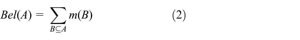
where the set B is the subset of A and m(B) is the basic probability number of B.
Definition 3: plausibility function
The plausibility function is defined as

Definition 4: Dempster’s combination rule
For

with
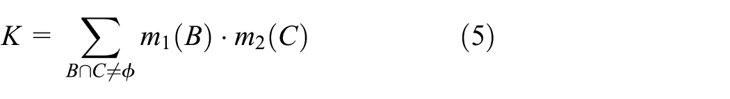
where B and C are both the focus elements,
The EN proposed by Simon et al.
29
to deal with cognitive uncertainty in reliability assessment and risk analysis is a directed acyclic graph (DGA), as well as the BN.
The EN diagnosis model mapped from the FTA model to realize quantitative fault analysis includes three activities: the model construction, the description of the conditional probability table (CPT) of EN parameters, and the acquisition of BPAs for network nodes.
Because of the similarities of the logical reasoning relationship between the EN model and the FTA model, we can map the FTA model to the EN model for quantitative diagnosis. Figure 4 shows the mapping relationships of “AND gate” and “OR gate” from the FTA model to the EN model. Figure 4(a) shows the mapping relationship of “AND gate,” and Figure 4(b) shows the mapping relationship of “OR gates,” where Ec is the child node variable, Ea and Eb are two parent node variables, and “AND” and “OR” represent the logical relationships of the two parent nodes, respectively.

(a) Mapping relationship of “AND gate” and (b) mapping relationship of “OR gate.”
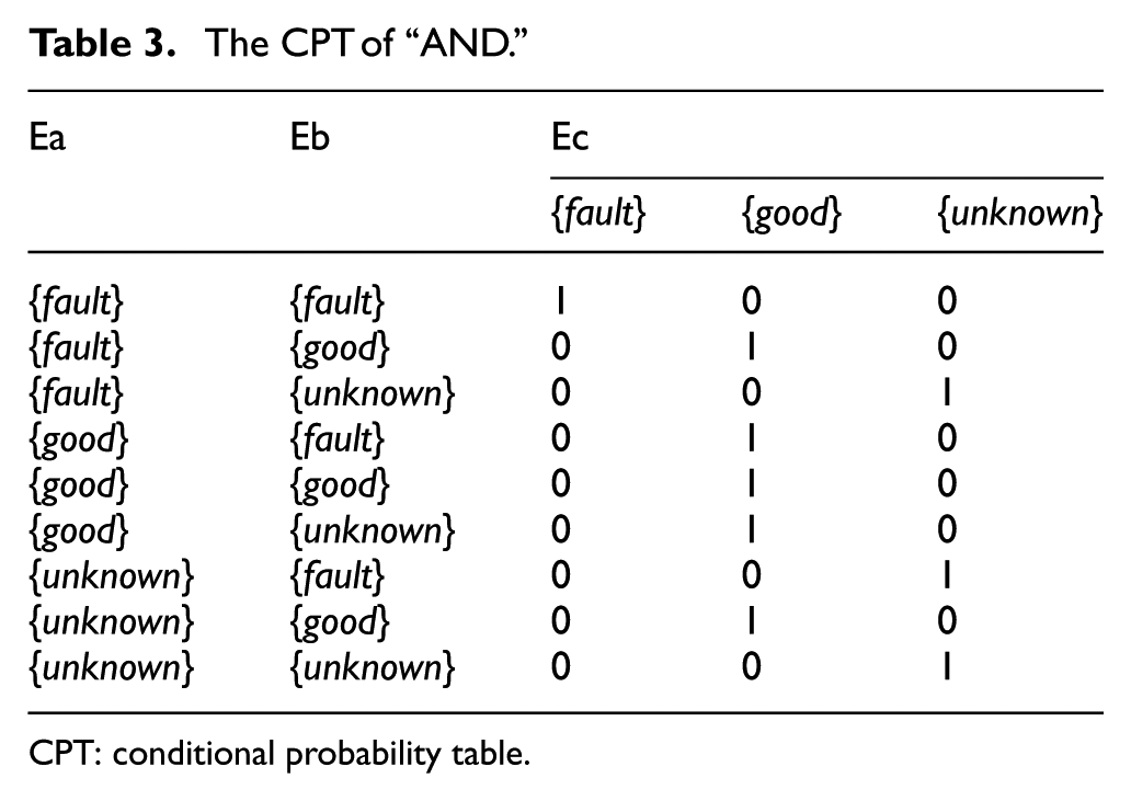
In the EN model, we suppose that each node has three states: {fault}, {good}, and {good, fault}; in other words, there will be three focal elements in the recognition frame. Here, we take {unknown} to substitute the focal element {fault, good} expressing uncertain information. The CPTs of the “AND/OR” relations in the EN model can be inferred from the logical relations represented by the logic gate in the FTA model. For example, in Figure 4(a), “AND gate” represents the logical relationship that the fault of Ec happens when Ea and Eb malfunction simultaneously. Based on the logical consistency between the two models, the CPT of “AND” in the EN model is shown in Table 3, and the CPT of “OR” is shown in Table 4.
The CPT of “AND.”
CPT: conditional probability table.
The CPT of “OR.”

CPT: conditional probability table.
In Table 3, the state of Ec is {fault} only when the states of Ea and Eb are both {fault}. If the state of Ea or Eb is {good}, the state of Ec is {good}. When the state of Ea is {unknown}, no matter whether the state of Eb is {fault} or {unknown}, the state of Ec is {unknown}. In addition, when the state of Ea is {fault} and the state of Eb is {unknown}, the state of Ec is also {unknown}.
When the logical relationship between Ea and Eb is “AND,” if the BPAs of Ea and Eb are obtained, the BPA of Ec can be calculated by equations (6)–(8) elicited from Table 3


In Table 4, the state of Ec is {fault} as long as the state of Ea or Eb is {fault}. The state of Ec is {good} only when the states of both Ea and Eb are {good}. When the state of Ea is {unknown}, the state of Ec is {unknown} whatever the state of Eb is {good} or {unknown}. When the state of Ea is {good} and the state of Eb is {unknown}, the state of Ec is {unknown}.
When the logical relationship between Ea and Eb is “OR,” if the BPAs of Ea and Eb are obtained, the BPA of Ec can be calculated by equations (9)–(11) elicited from Table 4


In this article, the data used to calculate the BPAs of the nodes in the EN model come from two sources: the after-sales data and the experience of experts. Due to the irregular, inaccurate, and omissive records, the after-sales data exhibit some uncertainties. Uncertainties also exist in the second type of data because of the knowledge level of the expert. Dempster’s combination rule can combine the two types of data to obtain the BPAs of the parent nodes. Before calculating the BPA of each parent node, we need to process the original after-sales data. For example, if the fault probability of Ea is 0.2, in general, the probability of {good} is 0.8. Then, there are
The case study
The numerical control (NC) rotary table is one of the important functional parts of various types of CNC borer, miller, and machining center. In this section, we take a certain type of NC rotary table as an example to demonstrate and verify the feasibility and effectiveness of the proposed approach. After the investigation into the fault data of the NC rotary table in a company, we find that the abnormal sound of the NC turntable is a frequent fault mode. Therefore, we diagnose this fault mode to find the fault position and the fault cause by the proposed method. Figure 5 shows the structure diagram of the NC rotary table and Figure 6 shows the FMA decomposition result.

The structure diagram of the NC rotary table.

The FMA decomposition structure of the NC rotary table.
As shown in Figure 6, the rotary indexing function of the NC rotary table is accomplished by the indexing motion and the brake/unclamping motion. The indexing motion is achieved by motor gear rotation meta-action, worm rotation meta-action, and worm wheel rotation meta-action. The brake/unclamping motion is conducted by the piston translation meta-action. Thus, we obtain four MUs: motor gear rotation MU (MU1), worm rotation MU (MU2), worm wheel rotation MU (MU3), and piston translation MU (MU4). Then, the abnormal sound fault analysis of the NC rotary table can be converted to the fault analysis of the four MUs with simple structures. The EN models are mapped from the FTA models of MUs. Taking the worm rotation MU as an example, the mechanical structure of MU2 is shown in Figure 7, the FTA model of the abnormal sound in Figure 8, and the EN model converted from the FTA model is shown in Figure 9. Coding instructions in the two models are presented in Table 5.
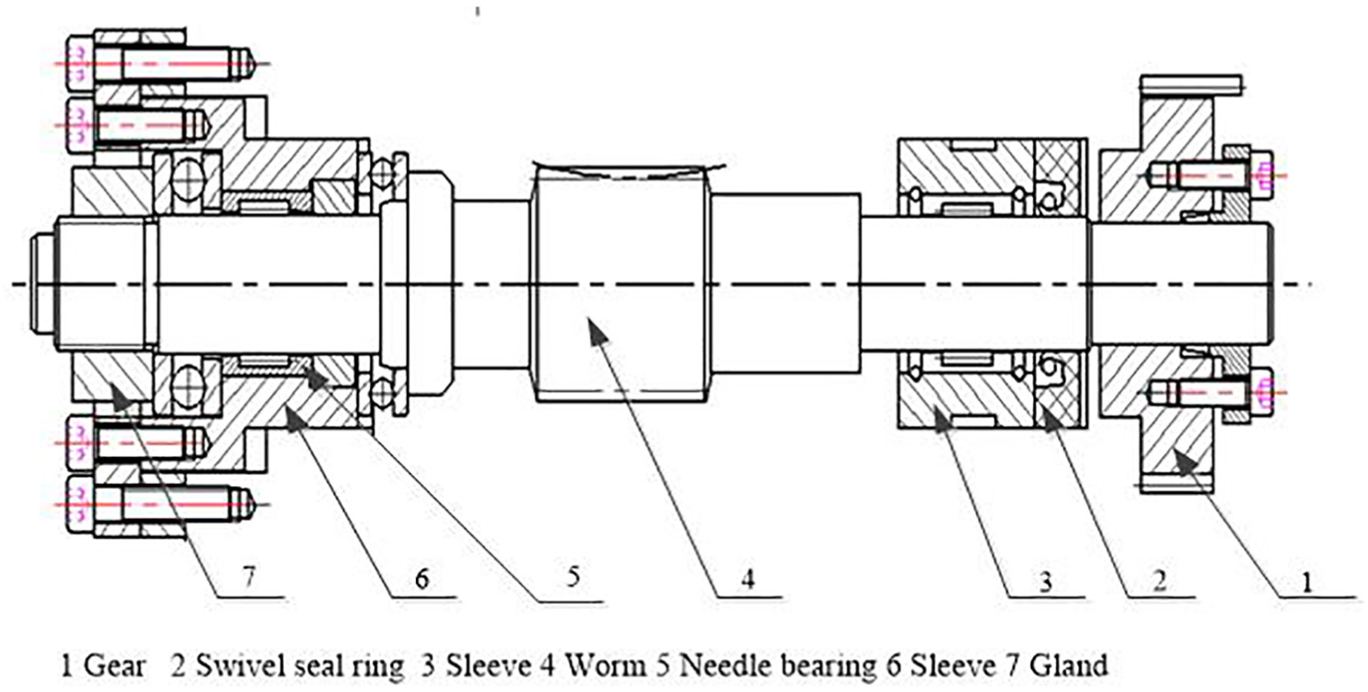
The mechanical structure diagram of MU2.

The abnormal sound FTA model of MU2.

The EN model of MU2.
Coding instructions of the two models.
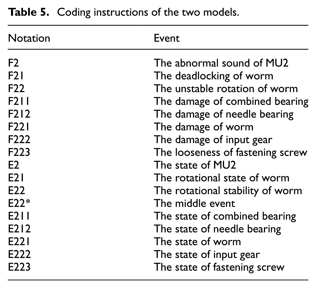
In Figure 9, the EN of worm rotation MU includes five parent nodes (E211, E212, E221, E222, E223) and four child nodes (E2, E21, E22, E22*). Each node has three states: {good}, {fault}, and {unknown}. Calculated from the after-sales data and expert experience information by equations (4) and (5), the BPAs of the five parent nodes are shown in Table 6. Then, according to the EN structure in Figure 9, the BPA of MU2 can be calculated by equations (9)–(11) as follows

The BPAs of the nodes of the worm rotation MU.

BPA: basic probability assignment; MU: meta-action unit.
Figure 10 comes from Table 6. In Figure 10(a), the credibility sequencing of the state {good} in MU2 is

The BPAs of the parent nodes in worm MU.
Similarly, the BPAs of MU1, MU3, and MU4 can be obtained from Table 7.
The BPAs of the four MUs.
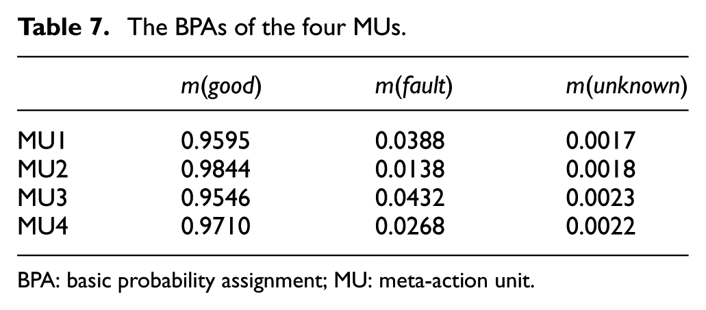
BPA: basic probability assignment; MU: meta-action unit.
All the data computations in this article are implemented in the software MATLAB 2010, Windows 10 system.
Figure 11 derives from Table 7. In Figure 11(a), the credibility ranking of the state {good} of four MUs is

The BPAs of the MUs in the NC rotary table.
Conclusion and contribution
This article applies the meta-action theory to the fault diagnosis activities of the complex mechanical system of product, and proposes a comprehensive qualitative and quantitative diagnostic method. First, we expand the FMA decomposition method into CFMA, SSFMA, and so on, and revise the definitions of meta-action and MU. Second, the MU-FTA method proposed to diagnose the mechanical fault qualitatively can transform the fault analysis of the mechanical system into the fault analysis of MUs. The MU-FTA model can greatly simplify the traditional FTA model. Third, we use the evidence theory to deal with uncertainties of quantitative diagnosis, apply Dempster’s combination rule to integrate the after-sales data and expert experience information to obtain the BPAs of network nodes, and map the MU-FTA model into the MU-EN model. The BPAs of MUs are obtained through network transmission. According to the credibility of the three states, the quantitative diagnosis of the complex mechanical system is accomplished. Finally, we take a certain type of NC turntable as an example to verify the feasibility and effectiveness of the proposed diagnostic method.
The proposed method is a comprehensive model–based and data-driven fault diagnosis method. Through researching the theory of meta-action deeply, we apply it to mechanical fault diagnosis activities of the complex mechanical system. Further research will focus on the fault propagation mechanism among the MUs and changes of the diagnostic method when considering the importance of different data sources.
Footnotes
Handling Editor: Xihui Liang
Declaration of conflicting interests
The author(s) declared no potential conflicts of interest with respect to the research, authorship, and/or publication of this article.
Funding
The author(s) disclosed receipt of the following financial support for the research, authorship, and/or publication of this article: This work was sponsored by the National Nature Science Foundation, China under Grant No. 51575070 and the National Major Scientific and Technological Special Project for “High-grade CNC Basic Manufacturing Equipment,” China under Grant No. 2016ZX04004-005.