
Abstract
In this article, a new particle tracking model is established through high temperature erosion modeling test. Based on the model, steam-particle flows in the governing stage cascade of a supercritical steam turbine are systematically investigated and the influence of oblique stator on the aerodynamic performance and erosion characteristics of governing stage blades is carefully studied. Results show that with the increase of nozzle oblique angle, the maximum load position gradually moves toward nozzle trailing edge. Consequently, secondary flow loss of nozzle cascade gradually decreases. Compared with the prototype structure of governing stage, stage efficiency increases by 0.8%, 0.35%, and 0.44%, respectively, when nozzle oblique angle increases to 15°, 30°, and 45°. Meanwhile, erosion at the trailing edge of nozzle pressure side and leading edge of rotor suction side gradually decreases, while erosion of rotor pressure surface increases. The maximum erosion position of nozzle pressure surface and rotor suction surface keeps constant, but the maximum erosion position of rotor pressure surface gradually moves forward. Comprehensive analysis shows that when nozzle oblique angle reaches 30°, erosion of nozzle trailing edge reduces by 14%, and stage efficiency increases by 0.35%; erosion resistance and aerodynamic performance of governing stage can be both well considered.
Keywords
Introduction
Solid particle erosion (SPE) of steam turbine components, including nozzles, rotors, valves, remains an intractable challenge for supercritical coal-fired power generation technology around the world. Erosion of steam flow path will first increase the roughness of cascade surface and then change the cascade profile, which have a great impact on the safety and efficient operation of steam turbines.1–3 Kawagishi et al. 4 indicated that aerodynamic performance of governing stage nozzles reduced by 3% because of SPE. Khaimov et al. 5 found that the unit efficiency decreased by 2.16% under part load operation due to SPE. With the development of ultra-supercritical technology, heat rate of units and the cost of electricity can be decreased in some extent by systematic thermodynamic analysis and structure optimization design. However, this economic advantage would be heavily discounted by SPE mentioned above.
Hard coating technology has been one of the most frequently used methods for enhancing the erosion resistance of turbine blade. Many relevant studies6–11 has been conducted in the past few decades, which show that thermal diffusion and thermal spraying are the most effective techniques for strengthening the surface of blades. However, hard coatings cannot always guarantee the protection of turbine blades12,13 due to the limited thickness and unavoidable coating defect.14,15 In fact, it was already proved by practical engineering that it is impossible to solve the SPE problem of turbine completely only through these passive anti-erosion measures.11,16 Therefore, initiative measures, such as optimizing the cascade profile, are adopted by different experts.
The essence of optimizing the cascade profile is to decrease the incidence velocity and angle of solid particles and reduce the amount of particles impinging on the trailing edge of blade. 17 Besides some studies4–6 from turbine manufacturers in the end of last century, Mazur et al.18,19 proposed that the erosion rate would be reduced by 50% if a small step is set near the nozzle trailing edge of pressure surface (PS). Dai et al. 20 and Wang et al. 21 indicated that with the employment of endwall contouring, erosion loss of nozzle decreases by 40%. With the continuous development of steam turbine design technology, a unique oblique stator structure, which is installed between the radial intake channel and axial turbine cascade in ultra-supercritical steam turbine high pressure cylinder and medium pressure cylinder, is proposed by some turbine manufacturers. This oblique stator intake structure not only plays as a diversion passage, but also reduces the problem of SPE of cascade.
Li et al. 22 studied the first-stage oblique stator in intermediate pressure cylinder of an ultra-supercritical steam turbine and found that with the increase of stator oblique angle, steam velocity and steam flow angle at stator outlet decreased; thus, erosion of the first-reheat stage cascade reduced. However, a depth analysis between the oblique stator structure and blade anti-SPE characteristic is lack of in the paper. Yang 23 pointed out that an oblique stator configuration of medium pressure cylinder can improve the distribution of pressure and reaction degree along the blade height direction, which is conducive to improving the economy of turbine stage. Based on the numerical research, Cai et al. 24 found that the reaction degree of the first-reheat stage cascade varies with the variation of stator oblique angle. As a result, blade erosion characteristics changes correspondingly. In addition, operation practice of some steam turbines in China also shows that steam turbine configured with oblique stator structure in high pressure first-stage cascade and medium pressure first-stage cascade exhibits better anti-erosion performance.
Summarizing the above literatures, it is found that steam turbines configured with oblique stator structure in high pressure first-stage cascade and first-reheat stage cascade may be the most effective method to reduce blade erosion. However, most of the above-mentioned references are qualitative studies; systematic quantitative results are lack of. Moreover, the specific anti-erosion mechanism of oblique stator structure is not yet fully understood. Based on the systematic high temperature accelerated erosion test results, a new particle tracking model is established in this article. Then, steam-particle flows in the governing stage cascade of a supercritical steam turbine are systematically investigated and the influence of oblique stator on the aerodynamic performance and erosion characteristics of governing stage blades are carefully studied. The relationship between nozzle oblique angle, blade erosion, and stage efficiency is first established. The precautions for the application of oblique stator structure are detailedly analyzed based on the combination of design and operating factors. The results of this study reveal the anti-erosion mechanism of oblique stator structure and provide a theoretical basis for preventing and reducing the erosion of high-parameter turbine blade.
Calculation scheme and numerical method
Calculation scheme
Figure 1 displays the schematic diagram of stage cascade meridian view. Oblique angle γ of nozzle is defined as the angle between the symmetry centerline of the nozzle (the dotted line in Figure 1) and the radial direction (axial Y in Figure 1). For governing stage cascade channel, construction process of oblique nozzle model is stated as follows.

Schematic diagram of the meridian view of a governing stage cascade.
Take the connection point O of the shroud line as the center of the circle, rotate the first-stage nozzle and its corresponding hub and shroud lines clockwise, so that different values of nozzle oblique angle γ can be formed. The arc segment S is approximately constructed by a segment of circular, which take point O as the circle center, and take blade height as the radius. This segment of arc is drawn so that the hub lines of oblique nozzle and rotating blade are connected smoothly. Through the above process, the oblique nozzle model of governing stage is obtained and displayed in Figure 2. In order to analyze the effect of oblique stator on the erosion characteristics and aerodynamic performance of governing stage cascade, four oblique angle working conditions, including γ = 0°, γ = 15°, γ = 30°, and γ = 45°are calculated in this article.
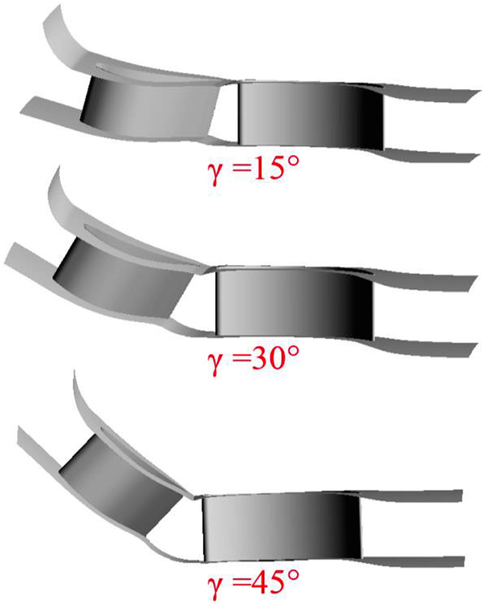
Oblique nozzle models of governing stage cascade.
Numerical approach
In this study, the time-averaged continuity equation, Navier–Stokes (N–S) equation, and energy equation are solved using a fully implicit discretization of the equations to simulate the three-dimensional viscous flow in steam turbine cascade. In view of the better performance in the simulation of flow with high strain rates, swirl, and separation, renormalization group (RNG) k–ε turbulent model is selected in this article to estimate the turbulence viscosity
Since the hub and shroud endwall of cascade channel are not straight after being tilted, especially the geometrical dimensions at the axial gaps between stator and rotating blades vary greatly from hub to shroud, it is difficult to guarantee the grid quality when discretizing the governing stage cascade with the HO-OH topology. Therefore, cascade channel with oblique stator structure is dispersed through O4H topology in this article. The minimum orthogonal angle of fluid domain is greater than 20°, and the maximum aspect ratio and expansion ratio are less than 300 and 3, respectively. The boundary layer mesh is refined and the dimensionless distance from the wall (
To validate the grid independence of numerical results on SPE of steam turbine blades, four meshes with the total number of 1 × 10⁵, 2 × 10⁵, 3 × 10⁵, and 4.5 × 10⁵ for one nozzle passage are studied and displayed in Figure 3. The cascade inlet mass flow and erosion weight loss on nozzle trailing edge are chosen as an assessment indicator. Simulation results under different grid number conditions are compared and shown in Table 1. It can be seen that the aerodynamic parameters of the turbine cascade are insensitive to the change of grid density. When the grid number of a single nozzle channel is refined from 1 × 10⁵ to 4.5 × 10⁵, the relative variation of the aerodynamic parameters of nozzle is less than 0.33%, while the relative change in erosion weight loss of nozzle trailing edge is close to 1%. When the grid number of nozzle channel is refined to 3 × 10⁵, the relative change in erosion weight loss of nozzle trailing edge is less than 0.06% when the grid density is further increased. At this time, it can be considered that the grid dependency of the computational result is negligible. In this article, total grid number of the entire governing stage cascade reaches 9 × 10⁵.

Mesh refinement process of governing stage nozzle.
Variation of mass flow and erosion loss with grid density in a single nozzle passage.

For the dilute particle phase of steam-particle flow in steam turbine cascade, one-way coupled dispersed particle group model is employed in the simulation. The main method is to integrate its instantaneous velocity vector

where

where

The total forces of the particles in the high-speed steam flow mainly include Stokes resistance, gravity and buoyancy, rotational force, additional mass force, pressure gradient force, Basset force, Magnus force, Saffman force, and thermophoretic force. In supercritical steam turbine cascades, because the particle density is much greater than the steam density, Stokes’ resistance force FD is two orders of magnitude higher than the other forces. Here, FD is proportional to the slip velocity

where

The particle Reynolds numbers

The validation of above aerodynamic performance and erosion computation method has been validated by Dai et al. 20 and Wang et al. 21
Boundary conditions
The boundary condition of this computation is set as follows. The total pressure and the total temperature at the inlet of the nozzle are 23.54 MPa and 813 K, respectively. The static pressure at the outlet of stage is 15.7 MPa. The design value of steam admission attack angle is 0°. The turbulence intensity is set to 5%. A no slip flow condition is set at all solid walls, and periodic conditions are applied on periodic boundaries of the passage. The surface roughness of a new blade is characterized with equivalent sand diameter Δ and is set to 1.8 μm. 25 The stage model, which performs a circumferential averaging of the fluxes through bands on the interface, is chosen as the frame change model.
Based on the investigations in literatures,3,5 the size of oxide particles in the flow path of steam turbine is usually smaller than 150 μm. Thus, totally seven kinds of particles, including 10, 20, 40, 60, 80, 100, and 120 μm, are seeded at the inlet of cascade. Meanwhile, particle concentration is set to 1 × 10⁻³ mg particles in per kilogram steam and a zero slip velocity for particles is chosen in the inlet of the cascade. Besides, particle shape factor
Erosion rate model and particle rebound model
In order to accurately simulate the motion and erosion behavior of flake oxide particles in turbine cascade channel, erosion rate model and particle rebound model must be established based on systematic high temperature test results. Besides, factors which will affect the test accuracy of particle erosion and rebound characteristics should be eliminated as much as possible in the test. Erosion rate model established through high temperature test results in the literature 3 is used in this article. During the erosion process, the differences in particle size and shape, the variation of surface morphology of the target, and the uncertainty of particle orientation on the wall surface result in a highly random motion behavior of flake particles. Therefore, establishment of particle rebound model requires extensive statistical analysis.
Based on the above considerations, following three measures are applied to improve the accuracy of particle rebound test. First, iron oxide particles with flaky characteristics are selected as erodent, and actual blade substrates are selected as targets. Through grade screening of particles, the concentration degree of particle size is improved, and the mutual interference between particles with difference size in the impact–rebound process is largely weakened. The morphology and size distribution of the erosion particles are shown in Figure 4.

Morphology and size distribution of the erosion particles: (a) flaky shape of erodent and (b) particle size distribution.
Second, following test conditions, including four particle impingement velocities (30, 60, 120, and 200 m/s) and six kinds of particle impingement angles (12°, 18°, 24°, 30°, 45°, and 60°) are selected in the test. The test temperature is in the range of 773–873 K. These test parameters are close to the impact parameters of oxide scales under actual steam turbine operation environment, which will guarantee the test effectiveness.
Third, a special narrow channel for particle rebound test is designed and set between the outlet of acceleration nozzle and target, as exhibited in Figure 5. This channel can filter the surrounding diffused particles and improve the orderliness of incident and rebound particles in the near wall region.
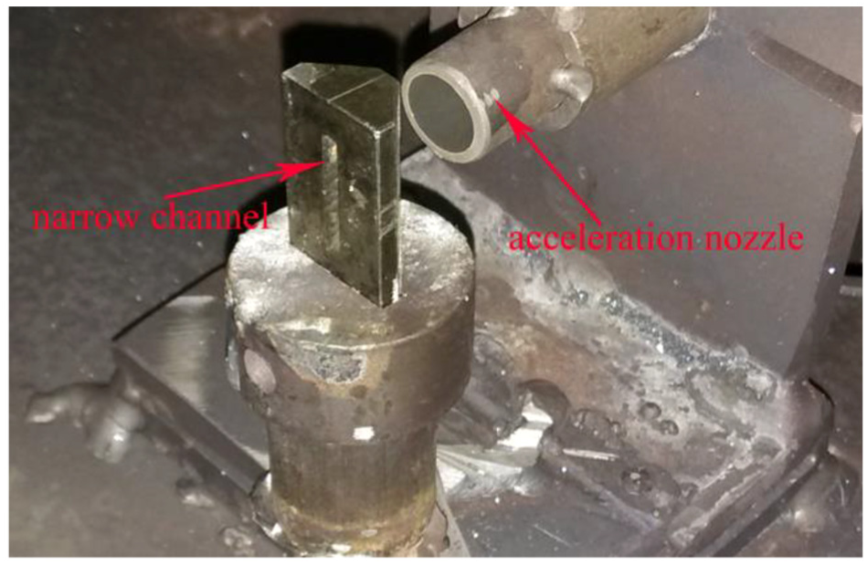
The special narrow channel in test chamber.
The basic test procedure is similar to that stated in the literature. 14 In the test, the compressed air is heated in the combustor to produce the required high-temperature gas. Then, the high-temperature gas flow is divided into two pipelines. Gas in one pipeline flows into the test chamber to heat the test target and establish the high temperature environment. Gas in the other pipeline enters the pneumatic nozzle to accelerate solid particles. Solid particles from the screw feeder are carried directly into the acceleration nozzle throat by the secondary air. After the acceleration by high-temperature gas flow, a uniform gas–solid mixture is produced in the nozzle, which will then pass through the special narrow channel and impinge the test target at an incidence angle β in the test chamber. During the process of interaction between particles and target surface, the particle velocity imaging (PIV) system is employed to measure particle velocity field. A region covering incident particles and rebounded particles is illuminated by the light sheet from the laser system; the motion information of particles is captured in the photos taken by the charge coupled device (CCD) camera.
Based on the statistical analysis on large amounts of test data, particle tracking model is finally established through least square fitting method. The fitting process is stated as follows. First, a statistical analysis on particle incident velocity and rebound velocity under different impact velocities and different impact angles is performed and the data anomalies are removed, so that the tangential restitution coefficient and normal restitution coefficient under different impact velocity and impact angle can be obtained. Second, the tangential restitution coefficient and normal restitution coefficient of particles at different incident velocities are averaged under the same impact angle, so that the average tangential restitution coefficient and the average normal restitution coefficient at different impact angles are obtained. Finally, the incident angle and tangential restitution coefficient, incident angle and normal restitution coefficient are fitted through least square fitting method, respectively, and the expression between incident angle and tangential restitution coefficient, the expression between incident angle and tangential restitution coefficient are obtained and shown in formulas (7) and (8)
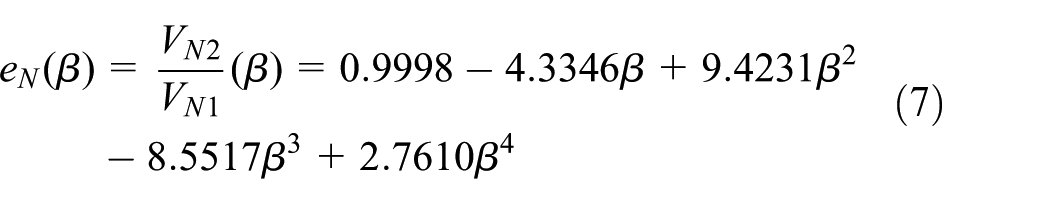

where β is the particle incidence angle and is measured by radians. VN1 and VT1 are the particle incident velocity, while VN2 and VT2 are the particle rebound velocity. The fitting error of particle rebound model is less than 5%.
Figure 6 shows the velocity restitution coefficient curves of different particles impacting on different plastic substrates. The rebound model in the figure represents the rebound characteristic of iron oxide particles impacting the 2Cr10MoVNbN substrate, which is also employed in this article. Tabakoff 26 model in the figure represents the rebound characteristics of 15 μm fly ash particles impacting 410 stainless steel; Forder et al. 27 model in the figure represents the rebound characteristic of quartz sand particles impacting AISI4130 steel. It can be seen that there is some difference in the velocity restitution coefficient value among the Rebound model, Tabakoff 26 model, and Forder et al. 27 model. However, the variation rule of velocity restitution coefficient with incidence angle is similar. In the test parameter range, tangential velocity restitution coefficient of the above three models decreases with the incidence angle first and then increases, which is shown in Figure 6(a). In Figure 6(b), normal velocity restitution coefficient of Tabakoff 26 model and Forder et al. 27 model gradually decreases with incidence angle, while normal velocity restitution coefficient of the Rebound model decreases with the incidence angle first at β = 12°–30° and then fluctuate in a certain range at β = 30°–60°.

Comparison of particle rebound models with different erodent–target combination: (a) tangential restitution coefficient curves and (b) normal restitution coefficient curves.
Careful analysis finds that the cutting of plastic targets from solid particles is mainly related to the change of particle tangential kinetic energy, while the normal kinetic energy of particles is mainly dissipated in the plastic deformation of target. Compared with fly ash particles used in Prof. Tabakoff 26 test and quartz sand particles used in Forder et al. 27 test, a stronger cutting force exerts on the target because of the distinct flaky characteristics of iron oxide particles used in this study. Therefore, the incidence angle corresponding to the lowest point (β = 18°) of tangential restitution coefficient (the maximum erosion rate point) is lower than that of the two other models (β = 30° and β = 45°). The magnitude of the normal restitution coefficient indicates that the rebound degree of flake oxide particles is lower than the particles tested in the two other models.
Results and discussion
SPE characteristics of governing stage blades
In order to analyze the steam-particle flow and erosion characteristics in governing stage cascade, relative surface coordinates (sr, hr) are defined in this article. Besides, the accumulated erosion weight loss
Figure 7 exhibits the trajectories of oxide particles with different sizes in the prototype governing stage cascade (γ = 0°). As is shown, trajectory of particles smaller than 10 μm in the cascade is close to the direction of stream flow, and a large amount particles escape without impacting cascade surface. With the increase of particle size, the impingement position on nozzle PS gradually moves forward; thus, particle impact probability increases, while the impingement velocity gradually decreases. In general, particles smaller than 100 μm will directly impinge the PS of nozzles and rotating blades in governing stage, and their maximum impingement velocity reaches up to 350 m/s.

Trajectories and velocity of oxide particles with different sizes under γ = 0° condition: (a) 5 μm, (b) 20 μm,(c) 40 μm, and (d) 100 μm.
Figure 8 further displays the contribution of particles with different sizes to erosion of governing stage nozzles PS under equal particle size distribution and measured particle size distribution. This two kinds of particle size distribution at the inlet of cascade can be found in Cai et al. 28 It is obvious that the region between sr = 0.7–1.0 at the trailing edge of nozzle PS is the most serious erosion area. Besides, particle size distribution at the inlet nozzle merely changes the specific value and proportion of the contribution of particles with different sizes to the erosion weight loss of nozzle trailing edge, while rankings of the contribution of each size particles do not change with the variation of particle size distribution. Under the condition of equal particle size distribution, particles in the range of 20–60 μm contribute about 56% to the erosion weight loss of nozzle trailing edge PS. In the measured particle size distribution, this proportion reached 85%. Obviously, if the high velocity impact on the trailing edge of the nozzle by small- and medium-sized particles can be mitigated, erosion condition of governing stage cascade will be greatly reduced.

Contribution of particles with different sizes to erosion of governing stage nozzle PS: (a) equal particle size distribution and (b) measured particle size distribution.
Effect of oblique stator on the erosion characteristics of governing stage
Figure 9 displays the erosion weight loss distribution along streamwise direction of governing stage nozzles and rotating blades at different oblique angles. It can be seen that compared with the prototype structure (γ = 0°), erosion weight loss on the PS of governing stage nozzles and rotating blades are all significantly changed under different oblique angles. With the increase of oblique angle, the maximum erosion location of nozzle PS is fixed near the nozzle trailing edge, and the erosion intensity is gradually reduced. However, the maximum erosion weight loss of rotating blade PS gradually increases with the increase of oblique angle, and the maximum erosion location gradually moves toward the leading edge of rotor. Furthermore, compared with the prototype structure (γ = 0°), erosion weight loss on the trailing edge of nozzle PS is reduced by 1%, 14%, and 15.2%, respectively, under γ = 15°, γ = 30°, and γ = 45° conditions, while the maximum erosion weight loss on the PS of rotating blade increases by 23.7%, 28.4%, and 48.1%, respectively. Meanwhile, the maximum erosion location on the PS of rotating blade moves from sr = 0.4–0.5 region to sr = 0.2–0.3 area. Correspondingly, erosion weight loss on sr = 0.0–0.2 of rotor suction surface (SS) leading edge decreases by 24.5%, 29.1%, and 64.4%, respectively.
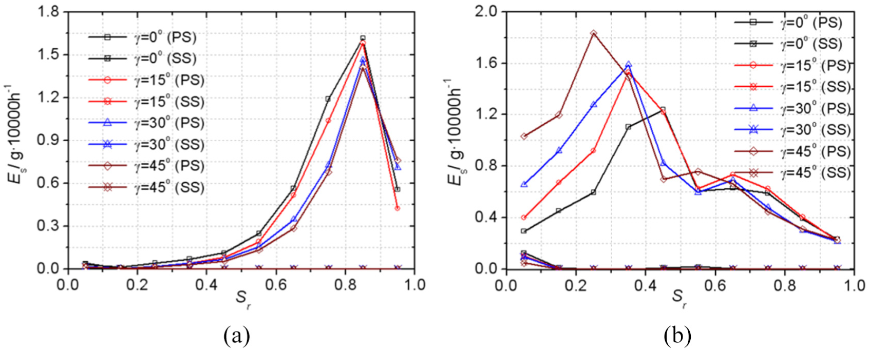
Erosion weight loss distribution of governing stage nozzles and rotating blades: (a) governing stage nozzle and (b) governing stage blade.
Figure 10 shows the particle impingement parameters on the surface of governing stage nozzles and rotating blades at different oblique angles. As is shown, the variation rule of particle impact parameters on the surface of the governing stage nozzles and rotating blades at different oblique angles is similar to that of erosion weight loss stated above. With the increase of the oblique angle, particle impingement velocity on nozzle PS gradually decreases, while particle impingement angle, which are all below 10°, changes a little. At the same time, particle impingement velocity and impingement angle on the PS (sr = 0–0.4) of rotating blades increase with the increase of oblique angle. Compared with the prototype structure (γ = 0°), particle impingement velocity on the PS of nozzle reduces by about 7.5%, while particle impingement velocity on the first half of rotating blade PS increases by about 13% under oblique angle γ = 30°.

Particle impingement parameters on the surface of governing stage cascade: (a) nozzle PS and (b) rotor PS.
Effect of oblique stator on the aerodynamic performance of governing stage
In order to reveal the mechanism of the effect of oblique stator on the erosion characteristics of governing stage cascade, aerodynamic performance of governing stage cascade is analyzed. Figure 11 displays the contour of Mach number distribution on the governing stage cascade at mid-span under different oblique angles. It is obvious that the maximum Mach number of steam flow in the cascades of governing stage gradually decreases as the oblique angle increases. Compared with the prototype structure (γ = 0°), the maximum Mach number of steam flow in the cascade channel decreases by 3.3%, 3.74%, and 3.86% respectively, under γ = 15°, γ = 30°, and γ = 45° conditions. Similarly, as the oblique angle increases, the range of local high velocity region near the leading edge of rotor SS gradually decreases, but the range of high velocity region in the rotating blade passage continuously expands, which is consistent with the change trend of particle impact velocity with oblique angle.
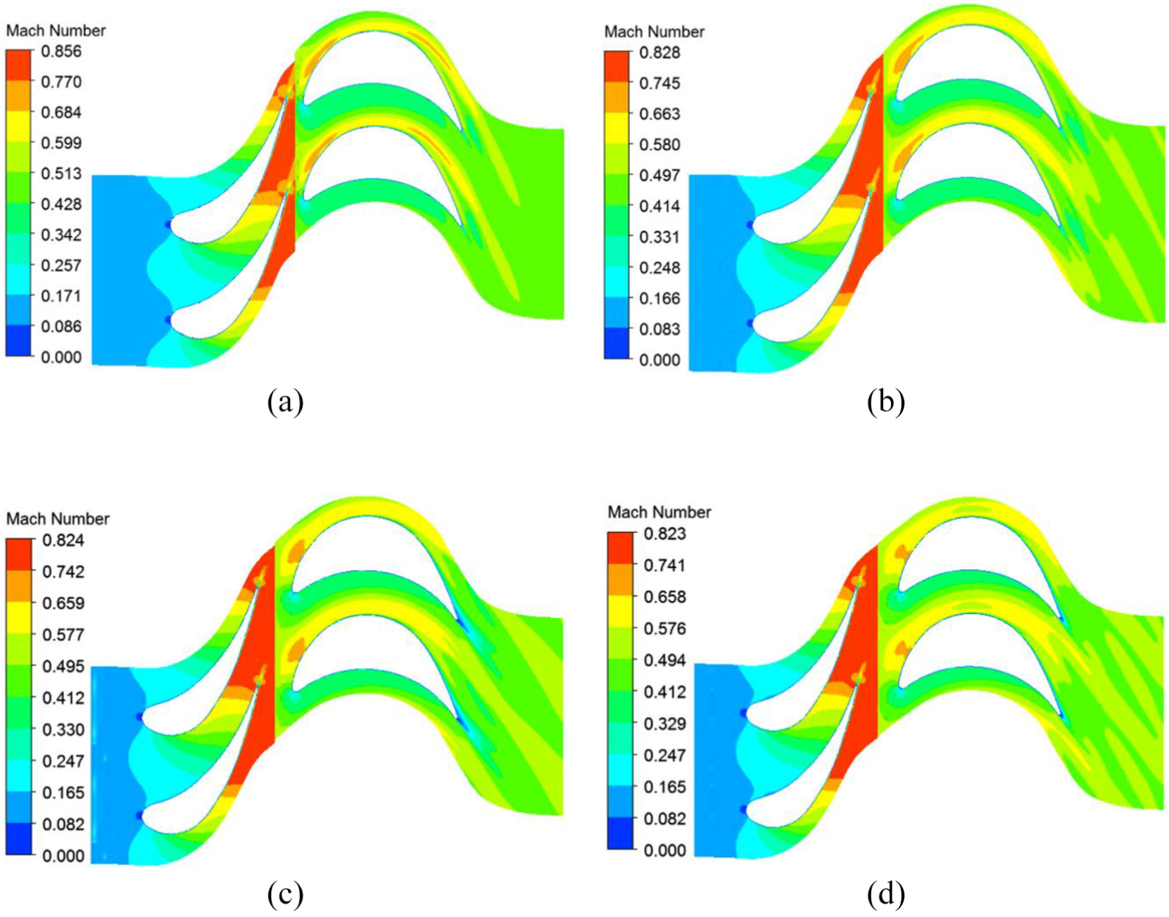
Contours of Mach number distribution on the governing stage cascade at mid-span: (a) γ =0°, (b) γ = 15°, (c) γ = 30°, and (d) γ = 45°.
Figure 12 shows the static pressure coefficient distribution on the governing stage cascade surface at mid-span. The horizontal coordinate represents the dimensionless streamwise location (X/B), and the vertical coordinate represents the aerodynamic parameter static pressure coefficient (Cps). The expression of Cps is shown in formula (9), where
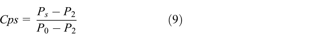

Static pressure coefficient distribution on the surface of governing stage cascade: (a) governing stage nozzle and (b) governing stage blade.
As can be seen, aerodynamic load in the nozzle passage gradually shifts backward with the increase of oblique angle, while the static pressure coefficient distribution on the rotating blade surface does not change greatly. The position of the lowest pressure point on nozzle suction side shifts from X/B = 0.8 to X/B = 0.843 when nozzle oblique angle increases from γ = 0° to γ = 45°. It is for this reason that the acceleration of steam flow is delayed in nozzle passage, and the average steam velocity in the oblique nozzle passage is reduced compared to the prototype nozzle structure.
Figure 13 exhibits the distribution of total pressure loss coefficient along blade height at the exit of governing stage. The vertical coordinate represents the relative blade height (hr), and the horizontal coordinate represents the aerodynamic parameter total pressure loss coefficient (
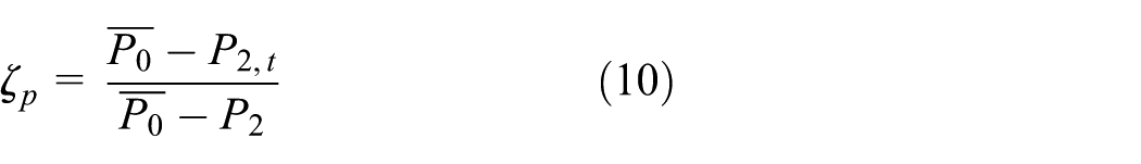

Distribution of total pressure loss coefficient along blade height at stage exit.
It can be seen that the difference of the massflow-averaged total pressure loss coefficient at the exit of governing stage under different oblique angle conditions is not very considerable. With the increase of nozzle oblique angle, the total pressure loss near the upper endwall of governing stage cascade is gradually reduced, while the total pressure loss at the middle span of governing stage cascade is slightly increased. Combined with the static pressure coefficient distribution on the surface of governing stage cascade, it can be found that with the increase of nozzle oblique angle, the aerodynamic load in nozzle passage shifts backward, and lateral pressure gradient between PS and SS of nozzle passage decreases. As a result, the development of endwall secondary flow is delayed and weakened. Therefore, the total pressure loss near the upper endwall slightly decreases.
Similarly, with the increase of nozzle oblique angle, delaying of steam flow acceleration in nozzle passage causes the boundary layer resistance loss on nozzle cascade surface gradually increase. At the same time, wake loss of nozzles gradually decreases due to the increase of the axial gap between governing stage nozzles and rotating blades. Under the combined effect of this two factors, profile loss of governing stage cascade increases slightly with the increase of oblique angle. Therefore, the total pressure loss coefficient in the main flow region of governing stage increases slightly with the increase of oblique angle in Figure 13. The calculation results show that the efficiency of governing stage increases by 0.8%, 0.35%, and 0.44%, respectively, when nozzle oblique angle increases from γ = 0° to γ = 15°, γ = 30, and γ = 45°.
Comprehensive analysis
Based on the analysis in the above two sections, it can be concluded that governing stage cascade with oblique stator structure can delay the acceleration of steam flow in nozzle passage, and the average steam velocity in nozzle passage is lower than that of the prototype governing stage cascade. Consequently, impingement velocity of particle with small and medium size on nozzle PS decreases. Meanwhile, with the increase of nozzle oblique angle, the axial gap between nozzles and rotating blades increases; kinetic energy of particles impacting the leading edge of rotating blades weakens; thus, erosion of the leading edge suction side of rotor is also reduced.
Compared with the prototype governing stage cascade structure (γ = 0°), governing stage cascade with γ = 30° nozzle oblique angle can reduce the erosion weight loss at the trailing edge of the nozzle by 14%, and the stage efficiency increases by 0.35%. When the nozzle oblique angle further increases to γ = 45°, erosion resistance of the nozzle enhances slightly, while erosion in the front half of rotor PS deteriorates rapidly. When the nozzle oblique angle decreases to γ = 15°, erosion resistance of nozzle is significantly reduced. Therefore, the computation results in this article show that governing stage cascade with γ = 30° nozzle oblique angle can ensure the erosion resistance and aerodynamic performance of governing stage cascade in a superior combination.
Although the oblique stator structure can reduce the erosion damage of governing stage blades to some extent, calculation results in this article show that erosion weight loss at the trailing edge of the nozzle is only reduced by 14% under the optimal nozzle oblique angle. Considering the supercritical steam turbine calculated in this article is designed in nozzle governing steam collection type, enthalpy drop in control stage is very large. If full admission steam intake mode and sliding pressure operations are applied to first stage, enthalpy drop distribution in each turbine stage is optimized. This not only greatly reduces the steam velocity in turbine cascade under each load condition, but also reduces the average concentration of oxide particles in a single nozzle passage. Therefore, in order to maximize the economy and advantages of SPE resistance, oblique stator structure must be applied with the optimization of enthalpy drop and full admission steam intake operation mode simultaneously in the designing of high-parameter steam turbine cascade.
Conclusion
Based on the erosion rate model and particle rebound model of blade material obtained through accelerated erosion test under high temperature, systematic numerical simulations of the effect of oblique stator on the aerodynamic performance and erosion characteristics of governing stage blades in a supercritical steam turbine are performed in this article. The main conclusions are as follows:
With the increase of nozzle oblique angle, erosion weight loss at the trailing edge of nozzle pressure side and leading edge of rotating blade suction side gradually decrease, while erosion weight loss on the PS of rotating blade increases. The maximum erosion weight loss position of nozzle PS and rotating blade SS keep constant, while the maximum erosion weight loss position of rotating blade PS gradually moves forward.
With the increase of nozzle oblique angle, the maximum load position gradually moves to nozzle trailing edge, and the average steam velocity in nozzle passage gradually decreases. As a result, secondary flow loss of nozzle cascade gradually decreases, while profile loss of nozzle slightly increases. Compared with the prototype structure of governing stage cascade, stage efficiency increases by 0.8%, 0.35%, and 0.44%, respectively, when nozzle oblique angle increases to 15°, 30°, and 45°.
Compared with the prototype governing stage cascade structure, governing stage cascade with γ = 30° nozzle oblique angle can reduce the erosion weight loss at the trailing edge of nozzle by 14% and increase stage efficiency by 0.35%. When the nozzle oblique angle increases to γ = 45°, erosion resistance of the nozzle enhances slightly, while erosion in the front half of rotor PS deteriorates rapidly. When the nozzle oblique angle decreases to γ = 15°, erosion resistance of nozzle is significantly reduced.
Governing stage cascade with γ = 30° nozzle oblique angle can ensure the erosion resistance and aerodynamic performance of governing stage cascade in a superior combination.
The results of this article will provide a theoretical basis for preventing and reducing the erosion of high-parameter turbine blade.
Footnotes
Appendix 1
Handling Editor: Jose Ramon Serrano
Declaration of conflicting interests
The author(s) declared no potential conflicts of interest with respect to the research, authorship, and/or publication of this article.
Funding
The author(s) disclosed receipt of the following financial support for the research, authorship, and/or publication of this article: The authors would like to thank for the financial support of Research Fund for the National Natural Science Foundation of China (NSFC) (no. 51606152) and Science and Technology Project of Huaneng Group Headquarters (no. HNKJ16-H09).