
Abstract
The Provincial Hospital Station of Guiyang Metro Line No. 2 in China is located on the upper-soft lower-hard stratum. In order to analyze the adaptability of primary support arch cover method for the project, the construction process of the main tunnel of the Provincial Hospital Station is simulated by virtue of numerical simulation. Meanwhile, the excavation process of the tunnel is simulated by the double-side drift method for comparison. The numerical simulation results show that the primary support arch cover method has advantages in settlement control, plastic zone distribution, and supporting structure safety. Only the primary supporting structure is relatively weak in the rock–soil interface and on the arch shoulders and vault, and liable to tension failure. However, the application of strengthened primary support can significantly improve this unfavorable situation. Therefore, it is suggested that the primary support arch cover method be adopted for the construction of the main tunnel of the Provincial Hospital Station. The numerical simulation results obtained by primary support arch cover method are consistent with the field data in terms of the change trend of surface settlement, and the final settlement value is also similar. On this basis, the influence of grade variation of underlying surrounding rock on surface settlement and surrounding rock plastic zone distribution caused by the two methods is further simulated, and the grade range of underlying surrounding rock suitable for primary support arch cover method is given in the article.
Keywords
Introduction
With the rapid development of economy and society and the accelerated process of urbanization, the exploitation and utilization of underground space has become an important measure to solve the three major crises, namely, urban population, resources, and environment, and a vital way to cure “urban syndrome” and to implement the sustainable development strategy in cities.1–7 As an important form of the exploitation and utilization of underground space, urban metro has been favored by people all over the world because of its safety, less pollution, punctuality, fast speed, large capacity, and low energy consumption.8–14
Metro construction always encounters the upper-soft lower-hard stratum, and the tunnel vault is usually located in the upper-soft soil layer of such compound stratum. However, due to the poor arching effect and low self-stability of soft soil, large deformation and surface settlement are easy to be induced. In order to solve the above problems, an arch cover method has been gradually formed recently based on the traditional large section construction method. Depending on the strength and stability of the arch structure, arch cover method can give full play to the bearing capacity of the underlying surrounding rock (the hard layer of the upper-soft lower-hard stratum). There are two types of the newly emerged arch cover method, namely, primary support arch cover method and two-lining arch cover method, both of which are relatively less used in engineering. At present, only a few cities such as Dalian, Qingdao, and Chongqing in China have been reported to have preliminarily applied the method to metro construction. 15 Ji and Jia 16 used large-scale model test to research the stress, deformation, and failure characteristics of the surrounding rock as the overload increase. They found that the damage zone mainly concentrated in the vault and it is the main source of lining structural damage and rock collapse load, as the extent of damage from dome to arch foot gradually increases. Shang et al. 17 adopted numerical simulation method to investigate the effect of different supporting measures’ combination in arch cover method on the control of the surrounding rock deformation during construction. The results showed that the method using double-layer primary support and additional big arch feet had the best control over surface settlement. Zhang et al. 18 analyzed the change trend of surface settlement caused by arch cover method during construction. They pointed out that the method caused the occurrence of surface settlement when the pilot tunnel face was constructed to about 20 m in front of the monitoring section. The settlement rate increased continuously with the decrease in the distance between the tunnel face and monitoring section. It reached the peak value after the pilot tunnel face penetrated the monitoring section for 5–10 m, and then decreased gradually until it became stable when the penetration distance was over 20 m. Song and He, 19 by virtue of numerical simulation method, analyzed the loosening features of surrounding rock around large-span tunnel in the upper-soft lower-hard rock stratum and the mechanical characteristics of supporting structure and secondary lining during construction using arch cover method. They identified main factors affecting the size of disturbed zone of surrounding rock and found that the superimposed bearing arch structure could depend on the stacked arch primary support to bear all the stratum load during construction. Lv 20 expounded on the key construction technologies of arch cover method and made detailed comparison between three construction sequences determined by the sequence of secondary lining, middle plate, and floor construction after the completion of the primary support in arch cover method. They suggested that full reverse construction sequence be chosen if without the assistance of abundant experience and relevant data. Besides, by numerical simulation method, Liu et al. 21 studied the effect of the sequence of dismantling temporary shoring and its single length on tunnel deformation during construction using arch cover method. The results indicated that alternate sequence and single length of 6 m exerted less influence on surrounding environment and thus provided a safer construction condition. The above studies have introduced the preliminary application of arch cover method in upper-soft lower-hard stratum, but the newly emerged method is far from popular in engineering. In addition, current research also has the following drawbacks: (1) the mechanical characteristics of surrounding rock and supporting structure during construction using arch cover method has not been compared with those of traditional construction methods, thus failing to demonstrate the advantages of arch cover method and (2) the influence of underlying surrounding rock grade on the applicability of arch cover method has not been clearly identified.
The Provincial Hospital Station of Guiyang Metro Line No. 2 in China is located on the upper-soft lower-hard stratum. In order to analyze the adaptability of primary support arch cover method for the project, the construction process of the main tunnel of the Provincial Hospital Station is simulated by virtue of numerical simulation method. Meanwhile, the excavation process of the tunnel is simulated by the double-side drift method characterized by effective settlement control and universal application for the purpose of comparison. Furthermore, the mechanical response of surrounding rock and supporting structure caused by the two construction methods are compared based on numerical results. The influence of grade variation of underlying surrounding rock on surface settlement and surrounding rock plastic zone distribution caused by the two methods is further simulated, and the grade range of underlying surrounding rock suitable for the primary support arch cover method is given in the article.
Overview of construction project
Overview of station
The Provincial Hospital Station, located on the north side of the intersection between South Baoshan Road and Dusi Viaduct in Guiyang, China, is the 23rd station of Guiyang Metro Line No. 2. The station is an underground two-layered island structure arranged in the north–south direction along Baoshan South Road. Within the range of the station site, the newly built outpatient building of Guizhou Provincial People’s Hospital lies on the northwest quadrant, about 50 m away from the main body of the station; both YishanBiyu Court and Guiyang Highway Administration Bureau lie on the northeast quadrant, around 16 m away from the main body of the station; rows of self-built half-uphill two/three-story houses lie on the southeast quadrant, about 10.4 m away from the main body of the station; Pantao Palace Overpass lies on the southern side of the station, around 39.3 m away from the main body of the station. The detailed location of the Provincial Hospital Station is given in Figure 1.
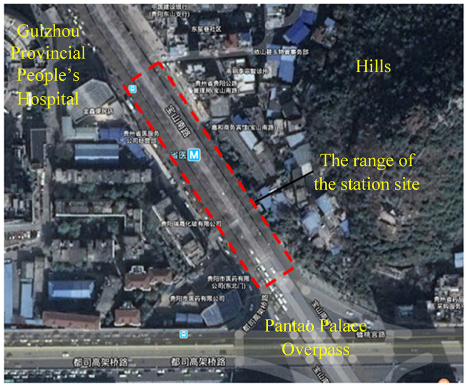
Location of the Provincial Hospital Station.
The main tunnel of the station is 200 m in length and 20.9 m in width. The buried depth of rail surface reaches 25.2–27 m, the area of the maximal section reaches 334 m2, and the thickness of overlying earth above the vault is about 7–11 m. Arguably, the tunnel can be called as a large-span shallow-buried super-large section tunnel.
Within the range of the station site, South Baoshan Road, with five fast lanes and four auxiliary roads on the two directions, is an arterial road in Guiyang. Due to heavy traffic, a pedestrian overpass has been built. According to the information provided by the municipal government, there is a dense pipeline network below the station site. For example, Φ1000 sewage pipe is a controlling pipe with a buried depth of 5.3 m, which cannot be moved during construction. If the excavation leads to large stratum deformation, important buildings and the underground pipeline network will be heavily damaged. Therefore, a suitable excavation method should be chosen to control the settlement in the safety range.
On the basis of the data from an onsite geological survey, the stratigraphic cross section consists of 3 m thick miscellaneous fill, 13.2 m thick red clay, and medium-weathered dolomite from top to bottom, in line with the “upper-soft lower-hard” characteristic. The station is mainly located on the medium-weathered dolomite layer, with the surrounding rock in grade IV. Most vaults are covered by weathered rock layer in the thickness of 0.5–5 m. Besides, some parts of the station lie on the red clay layer.
Construction method
In view of the upper-soft lower-hard stratigraphic characteristic of this large-span embedded station and enormous municipal pipelines, large traffic flow, and strict settlement requirement above the main tunnel, the primary support arch cover method might be adopted for construction.
Primary support arch cover method, on the basis of open cut method, cover excavation method, and pile-beam-arch (PBA) method, is an excavation construction method aimed at upper-soft lower-hard strata and rock–soil composite strata. When this method is applied, the tunnel cross section is divided into upper and lower parts and excavated separately. The upper part is subdivided into pilot tunnels on both sides and rock pillars in the middle. The upper rock mass of the arch cover is pre-supported in advance according to the situation before excavation. Then the pilot tunnels are excavated. After the excavation, primary support is carried out. Big arch foot vertical beams are set up, and surrounding rock bolts are used to reinforce weak surrounding rock. After forming a complete cross section of the arch cover, the construction of primary support is strengthened. The excavation of the lower half section is based on the strengthened primary support in the upper part. First, the middle rock mass is excavated without protection. Next, the rock mass on both sides is excavated. The construction procedure of the primary support arch cover method is shown in Figure 2. The basic construction steps are as follows:
Large pipe sheds and small leading conduits are filled with concrete to reinforce the weak surrounding rock.
Soil mass ①–④ in Figure 2, namely, the upper left and right pilot tunnels, are excavated and provided with primary support (bolts, small conduits, steel frames, shotcrete, and temporary support).
Soil mass ⑤, namely, the upper middle pilot tunnel, is excavated and provided with primary support (bolts, small conduits, steel frames, shotcrete and temporary support).
Soil mass⑥–⑦, another two pilot tunnels, are excavated and provided with transverse braces.
Feet-lock bolts are built on big arch feet (ensure that there is about 0.5 m of anchoring to improve the primary support), the upper shotcrete of temporary support is chiseled, and the primary support concrete is strengthened by mode construction, three of which are conducted cyclically.
When the strengthened primary support concrete reaches the design strength, both the temporary support and transverse braces are removed and the upper core soil mass ⑧ is excavated.
The lower middle soil mass ⑨ is excavated. After adding shotcrete, the lower left and right soil mass ⑩–⑬ are excavated and provided with sidewall primary support.
The lower central soil mass ⑭ is excavated. After offering inverted arch primary support, the lower left and right soil mass ⑮–⑯ are excavated and provided with sidewall primary support. The primary support is completely closed. The waterproof layer is laid and the secondary lining is poured.
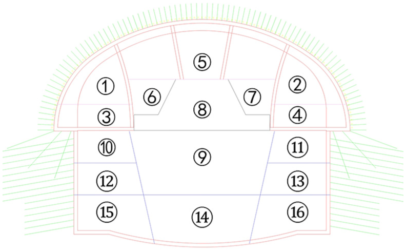
Construction procedure of primary support arch cover method.
In accordance with the previous analysis, the Provincial Hospital Station needed a large-span excavation construction method to ensure the stability of underground space and control surface settlement. In fact, the double-side drift method has been widely used in large-span tunnel because of its good control of surface settlement and safe construction. Therefore, the double-side drift method was chosen as the method compared with the primary support arch cover method for the construction of the Provincial Hospital Station.
Numerical simulation and analysis
With the rapid development of computer technology, numerical simulation has become an important method of studying the stability of surrounding rock in underground projects.22–27 To contrastively analyze the settlement of surrounding rock, the stress of supporting structure and the plastic zone of surrounding rock caused by excavation following the primary support arch cover method and double-side drift method, the numerical simulation method was used in this article.
Geological model and boundary conditions
After selecting the representative cross section of the station, a three-dimensional geological model of the Provincial Hospital Station to be excavated via the primary support arch cover method was established based on the large finite element software Midas GTS NX, as shown in Figure 3. The red grid denoted the controlling sewage pipe. The model consisted of 205,086 units and 36,693 nodes. The model of the main tunnel was depicted in Figure 4, and the Y direction was the direction of tunnel excavation.

Overall model of the Provincial Hospital Station.
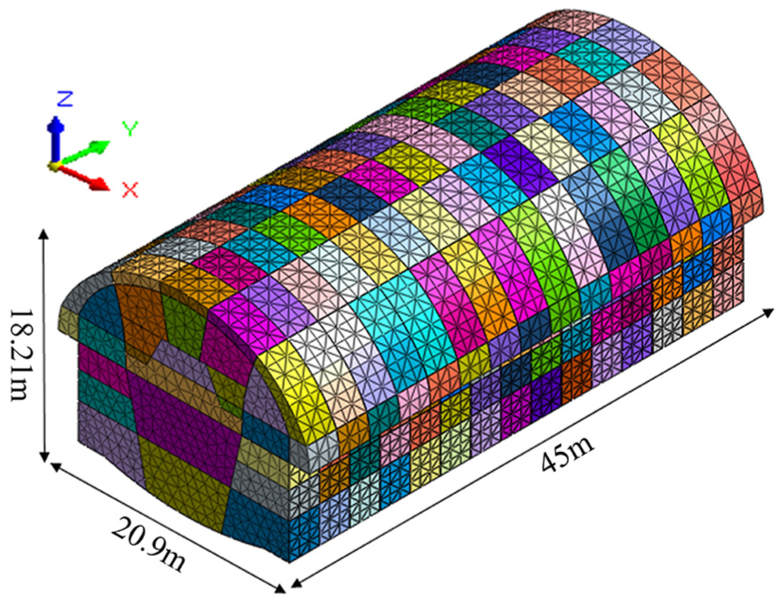
Model of the main tunnel.
To eliminate the influence of boundary size on the numerical test results, the left and right boundaries were set as five times the tunnel diameter (R = 10.45 m) away from the midline of the station tunnel, that is, 50.25 m; the lower boundary was set as four times the tunnel diameter away from the midline of the station tunnel; the upper boundary was selected according to the buried depth of the metro station. The buried depth reached 28.2 m, so the length of the boundary in the X, Y, and Z directions was 104.5, 45, and 70 m, respectively. The surrounding rock and strengthened primary support were simulated by solid elements with a Mohr–Coulomb model as the constitutive model.28–31 The primary support, temporary support, and secondary lining were simulated by plate elements with an elastic structure as the constitutive model. The sewage pipe was simulated by embedded beam elements with an elastic structure as the constitutive model. The front, back, left, and right facades and the lower boundary of the model were constrained by normal displacement, while the ground surface was a free boundary. All construction steps in each construction method were closely linked. There was a footage of 3 m every excavation.
Parameters of materials
According to the geological survey report, the values of physical and mechanical parameters of studied strata were shown in Table 1.
Physical and mechanical parameters of rock and soil layers.

The support was in the form of steel arch shotcrete. The elastic modulus of C25 shotcrete, C30 shotcrete, and steel arch was 23, 31.5, and 210 GPa, respectively. According to the stiffness equivalence method 32 and equation (1), the elastic modulus of steel arch was converted to that of concrete, and the elastic model of primary support was calculated equivalently. The mechanical parameters of supporting structures after calculation were demonstrated in Table 2
Physical and mechanical parameters of supporting structures.


where Ec referred to the elastic modulus of the concrete after conversion; E0, the elastic modulus of the original concrete; As, the sectional area of the steel arch or grille; Es, the elastic modulus of the steel; and Ac, the area of the concrete.
Analysis of calculation results
Surface settlement and vault settlement
The excavation of a metro station tunnel in cities will inevitably disturb the stress field of the original land, causing the redistribution of stress and the settlement of surface and important buildings.8,33,34 Therefore, it is highly important to predict the possible settlement during construction. After the construction based on the two methods, Figures 5 and 6 described surface settlement trough curves when Y = 20.45 m and vertical displacement diagrams of the sewage pipe, respectively.

Surface settlement trough.

Vertical displacement of the sewage pipe: (a) Primary support arch cover method and (b) double-side drift method.
Judging from Figure 5, the horizontal surface settlement caused by the primary support arch cover method was smaller than that by the double-side drift method, with the maximal settlement value at 19.99 and 24.65 mm, separately. In addition to the larger settlement, the double-side drift method also resulted in slight uplift of the surface beyond the 30 m range away from the station center; afterward the settlement near the midline of the tunnel developed rapidly, showing the characteristic of “broad and deep.”
Figure 6 showed that the maximal settlement value and the uplift value of Φ1000 sewage pipe were 23.345 and 0.213 mm after the construction based on the primary support arch cover method, and 29.557 and 0.468 mm after the construction based on the double-side drift method, suggesting that the primary support arch cover method had less influence on the controlling pipe.
Figure 7 displayed the variation of surface settlement and vault settlement with changing excavation steps above the midline of the tunnel at 8 m away from the initial excavation face by the two construction methods. Generally speaking, both surface settlement and vault settlement caused by the primary support arch cover method were smaller than those by the double-side drift method. Concerning the surface settlement, the settlement process incurred by the primary support arch cover method was short, especially in the rapid settlement stage. Although the settlement developed at an average rate of 2.14 mm/excavation step after the second excavation step (S2), the growth rate slowed obviously after starting to improve the primary support (S10) on the arch, and basically no longer increased and gradually stabilized after finishing strengthening the primary support (S11). On the contrary, although the excavation steps were fewer and the procedure was simpler during the construction based on the double-side drift method, the whole settlement process lasted for a longer time. On the contrary, the vault settlement was in line with the surface settlement in the very beginning for both construction methods. Afterward, the vault settlement incurred by the primary support arch cover method tended to differ from the corresponding surface settlement earlier and then developed quickly, but the settlement rate was lower and the duration was shorter in comparison with the double-side drift method. Finally, the growth rate after S10 slowed down; the vault settlement gradually became stable and consistent with the surface settlement.
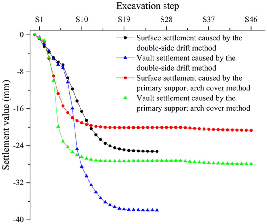
Surface settlement and vault settlement.
Internal force of supporting structures
As a part of the tunnel structure bearing system, primary support and surrounding rock constrain each other and bear all the loads jointly during the construction. Primary support is of great significance to fully play the stability of surrounding rock and to ensure the safe and normal construction. Plate units in the middle of primary support were chosen for research, as shown in Figure 8. Figure 9 gave a diagram of horizontal (X-axis) and vertical (Y-axis) axial force of primary support, in which positive values represented tension stress while negative values represented pressure stress.
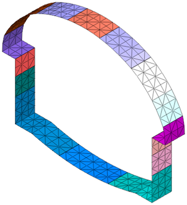
Primary support.
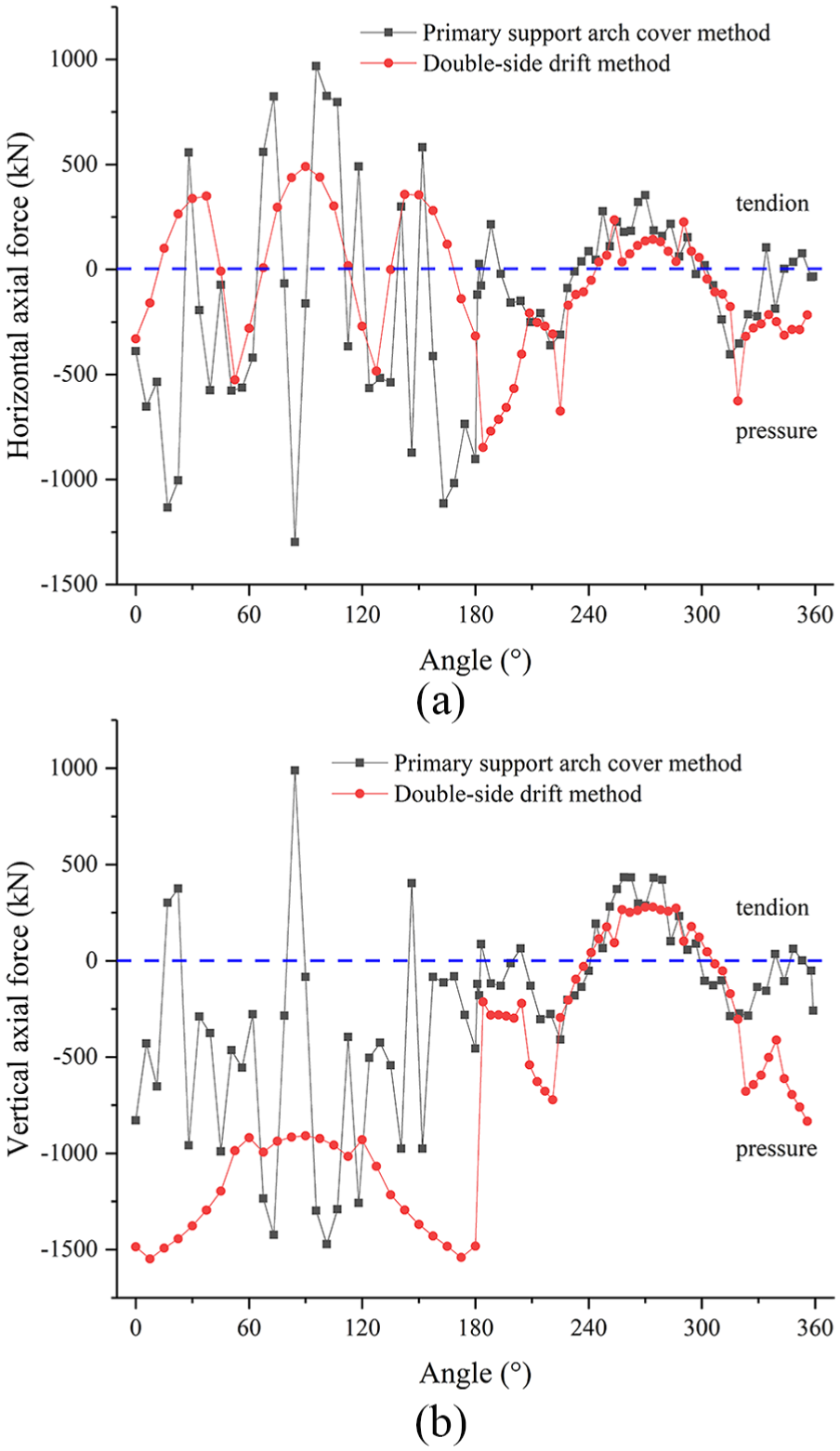
Axial force of primary support: (a) Horizontal axial force and (b) vertical axial force.
As could be seen from Figure 9, the maximum horizontal tension and pressure and the maximum vertical tension caused by primary support arch cover method were all greater than those caused by double-side drift method, while the vertical maximum pressure brought about by the former was slightly smaller than that by the latter. In addition, the horizontal and vertical axial forces caused by the former method varied more frequently than those by the latter, resulting in frequent shift between the tension and pressure zones which would affect the safety of the primary support. This is mainly because the upper half section excavation procedure of the primary support arch cover method is cumbersome, and there are many guide holes which influence each other, leading to the multi-stage closure of the supporting structure. Therefore, the “arch cover” caused by the primary support arch cover method could be easily damaged, thus highly demanding the stability of supporting structures. Hence it was necessary to further calculate the safety coefficient of the structure to determine its safety and possible damage forms.
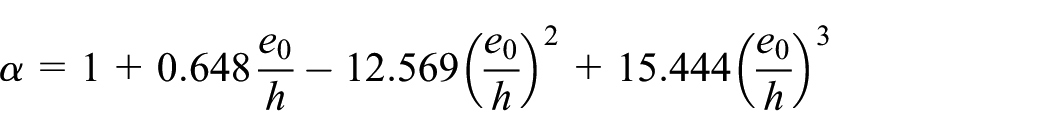
According to the regulations, 35 the safety coefficient of an arch unit could be calculated through formulae (2) and (3). The results were shown in Table 3.
Safety coefficients of supporting structures.

When e0 = M/N ≤ 0.20 h, the compressive strength of the material was in control

When e0 = M/N > 0.20 h, the tensile strength of the material was in control

where k was the safety coefficient; φ, the vertical bending coefficient of the component, with φ = 1; Ra, the ultimate compressive strength of the material; R1, the ultimate tensile strength of the material; b, the width of the section, with b = 1; h, the thickness of the section; α, the coefficient influencing the eccentricity of axial force, as could be calculated by the following formula
The calculation results in Table 3 indicated that the safety coefficient of primary supporting structures used in the primary support arch cover method varied greatly, which was consistent with the axial force variation, and that the structure was affected by uneven stress. Although the average safety coefficient was relatively large, the safety coefficient at the interface between rock and soil, on both sides of arch shoulders and vault was smaller than that caused by the double-side drift method, making the structure liable to tension failure. After strengthening the primary support, the safety coefficient of supporting structures was significantly improved, thereby ensuring the safety and stability of the structure.
Plastic zones of surrounding rock
The distribution of plastic zones of surrounding rock can directly reflect the safety and stability of surrounding rock and support system of underground structures. 32 Figure 10 showed the plastic zone distributions of surrounding rock after the construction, respectively, via the two methods. It could be seen that both the plastic zones caused by the two methods were distributed at the arch feet and two abutments, but the plastic strain values and plastic zone distribution brought about by primary support arch cover method were relatively smaller. This was because strengthened primary support was built near the arch cover. The load of soil column was mainly borne through big arch feet and then transferred to the medium-weathered dolomite, which fully exerted the bearing capacity of medium-weathered dolomite.

Distribution of plastic zones: (a) Primary support arch cover method and (b) double-side drift method.
According to the above analysis, the primary support arch cover method had advantages in settlement control, plastic zone distribution, and supporting structure safety. Only the primary supporting structure was relatively weak in the rock–soil interface and on the arch shoulders and vault, and liable to tension failure. However, the application of strengthened primary support could significantly improve this unfavorable situation. Therefore, it was suggested that the primary support arch cover method be adopted for the construction of the Provincial Hospital Station in Guiyang Metro Line No. 2.
Field monitoring
According to the numerical simulation results, the main tunnel of the Provincial Hospital Station of Guiyang Metro Line No. 2 was constructed via the proposed arch cover method. The surface settlement was monitored during the construction for security reasons. The layout of monitoring points for the four sections (I, II, III, and IV) within the numerical simulation range of the Provincial Hospital Station was given in Figure 11 where the red double solid line denoted the contour of the station, and the blue dotted line denoted the contour of numerical simulation sections. The distance was 10 m between every two monitoring sections, and monitoring point #1 was located above the central axis of the tunnel. The distance from the left boundary of the numerical simulation section to monitoring section I was 8 m, while that from its right boundary to monitoring section IV was 7 m.

Layout of certain monitoring points of the Provincial Hospital Station.
Analysis of monitoring results
The settlement data of two monitoring points #1 and #2 in monitoring section I in Figure 11 were selected for analysis. The curves of cumulative settlement values of monitoring points #1 and #2 with the increase in time were shown in Figure 12 which revealed similar change trends of the two monitoring points. The settlement process could be divided into five stages, namely, stage 1—initial settlement, stage 2—rapid settlement, stage 3—settlement stop, stage 4—secondary settlement, and stage 5—stable settlement. Stage 1—initial settlement: at this stage, the two monitoring points began to settle as a result of the excavation of the left and the upper right pilot tunnels ①-④ (see Figure 2). The settlement rates gradually increased as the tunnel face advanced forward. However, the influence of construction disturbance on the deformation of surrounding rock was relatively small due to the large distance between the two points and the tunnel face. Therefore, the settlement values of the two points at this stage were generally small, the final values being 1.02 and 1.07 mm, respectively. Stage 2—rapid settlement: at this stage, the settlement of the two monitoring points lasted for a short period of time with a great rate. The reason was that the increasingly short distance between the tunnel face and monitoring section I due to the continuous excavation of the left and the upper right pilot tunnels ①-④ exerted increasing influence on surrounding rock deformation. Consequently, the settlement values of the two points increased dramatically until it became stable when the pilot tunnel face penetrated monitoring section I for some distance. The cumulative values of the two points at this stage reached 9.41 and 10.65 mm, separately. Stage 3—settlement stop: the settlement of the two points basically remained unchanged at this stage. The reason was that the monitoring section I was certain distance behind the left and upper right pilot tunnels ①-④ and was far enough from the upper middle pilot tunnel ⑤ (see Figure 2), thus unaffected by their excavation. The cumulative settlement values of the two points at this stage remained in the range of 7.74–9.41 mm and 9.84–10.65 mm, respectively. Stage 4—secondary settlement: the settlement values of the two points increased again at the stage due to the excavation of the upper middle pilot tunnel ⑤ which shortened the distance between the tunnel face and the monitoring section I and thus enhanced the influence on surrounding rock deformation. Besides, the excavation of pilot tunnels ⑥ and ⑦ (see Figure 2) also showed some effect on the deformation. Therefore, the settlement of the two points lasted longer at this stage, and the values reached 22.03 and 19.94 mm, respectively. Stage 5—stable settlement: the settlement of the two points gradually stabilized at this stage. The main reason was that the monitoring section I was far enough from the left and upper right pilot tunnels ①-④ and from the upper middle pilot tunnel ⑤, and the strengthened primary support had been completed and played the major bearing role. Thus, the continuous excavation of pilot tunnels almost exerted no influence. The final settlement values of the two measuring points were 23.18 and 19.99 mm, respectively, both within the limit of surface settlement value (30 mm) prescribed by the project design.

Curves of cumulative surface settlement values:(a) Monitoring point #1 and (b) Monitoring Point #2.
Comparison of field monitoring and numerical simulation results
Figure 12 revealed the change trends of cumulative settlement values of monitoring points #1 and #2 with excavation steps obtained by numerical simulation. Furthermore, Figure 13 showed the comparison between the measured surface settlement curves and the numerical simulation results of the five monitoring points with stable settlement in section I (see Figure 11). Judging from Figures 12 and 13, the field monitoring results shared the similar settlement trend with the simulation results. However, there was a settlement stop stage (see stage 3 in Figure 12) in monitoring results, while the surface settlement curve obtained by numerical simulation was relatively smooth without stop stage. This was mainly because ideal situation in numerical simulation was considered and construction steps were thought as closely linked. In addition, compared with the monitoring data, the numerical simulation results were generally smaller. The deviations between the simulated final settlement values of points #1 and #2 and the field data were 2.55 and 2.43 mm, respectively, and the average deviations of the five monitoring points in section I were 2.17 mm. The reason was that the rock (soil) material was assumed as homogeneous and isotropic continuous medium while conducting numerical calculation, ignoring the influence of mechanical behavior of joints and cracks in rock (soil) and resulting in smaller numerical simulation results than the field data. Nonetheless, the correctness of the general law would not be affected. Therefore, the above comparison demonstrated that primary support arch cover method could effectively control surface settlement during the construction of the main tunnel of the Provincial Hospital Station, and the construction method was reasonable and feasible.

Comparison of settlement in section I.
Discussion
As could be seen from the above analysis, the primary support arch cover method had notable advantages in settlement control, plastic zone distribution, and supporting structure safety, owing to the fact that vertical beam bearing was formed by the construction of big arch feet and the main load was transferred to the medium-weathered dolomite with high stability and bearing capacity.
Tunnel surrounding rock can be divided into different grades according to rock strength, rock mass integrity, and structural state, and its physical and mechanical parameters can be used as the classification index of surrounding rock grade. To further clarify the primary support arch cover method’s applicable stratigraphic conditions and strength requirement for underlying surrounding rock, the physical and mechanical parameters of underlying surrounding rock (medium-weathered rock) in Figure 2 were changed (changes in surrounding rock grades was characterized by changes in surrounding rock parameters), and both surface midline settlement and plastic zone distribution caused by the two construction methods were comparatively analyzed by the numerical simulation method.
According to the range of physical and mechanical indicators of surrounding rock at all grades recommended by relevant regulation, 35 the average values of other parameters were taken as the physical and mechanical parameters of surrounding rock in a certain grade with bulk density unchanged. For example, for grade III surrounding rock, the elastic modulus ranged between 6 and 20 GPa, the internal friction angle ranged between 39° and 55°, the cohesive force ranged between 700 and 1500 kPa, and the Poisson’s ratio ranged between 0.25 and 0.3. Accordingly, the average values of these parameters were set as 13 GPa, 44.5°, 1100 kPa, and 0.275, respectively. This method of determining the parameters also went for surrounding rock in other grades. The physical and mechanical parameters of surrounding rock in different grades were shown in Table 4.
Physical and mechanical parameters of surrounding rock in different grades.

Figure 14 gave the distribution of 12 measuring points which were in increasing arrangement according to the direction of excavation in the surface midline. Using the parameters in Table 4, surface midline settlement values under the condition of underlying surrounding rock in various grades were compared based on numerical calculation, as shown in Figure 15.

Distribution of measuring points.

Surface midline settlement comparison of underlying surrounding rock in different grades: (a) Grade III, (b) Grade IV,(c) Grade V, and (d) Grade VI.
It could be inferred from Figure 14 that the settlement values caused by the primary support arch cover method were smaller than those caused by the double-side drift method concerning surrounding rock in all grades. Arguably, the primary support arch cover method enjoyed considerable advantages in terms of surface settlement control. The surface midline settlement value caused by the two methods tended to be small in the middle while large on both ends with changing location of measuring points, which was mainly related to the application of temporary support and the time of demolition. To go into detail, the settlement value was larger in the point close to the excavation face, given that temporary support could not be applied timely in the early stages of excavating pilot tunnels; the surface settlement value began to decrease after the temporary support was applied; the surface settlement value increased again when the temporary support was gradually demolished in the later stages of construction. Therefore, it was necessary to grasp the opportunity of temporary support application and demolition in the process of construction.
To vividly compare the surface settlement caused by the two construction methods under the condition of surrounding rock in different grades, the maximal, minimal, and average values of surface midline settlement were summarized in Table 5.
Surface midline settlement of surrounding rock in different grades.

As shown in Table 5, the maximum, minimum, and average values of the surface midline settlement under the condition of surrounding rock in different grades caused by the primary support arch cover method were smaller than those caused by the double-side drift method. With decreasing surrounding rock grade, the difference in the average settlement caused by both methods first increased and then decreased. In general, the primary support arch cover method had better control of surface settlement than the double-side drift method did.
Figures 16–18 showed the plastic zone distributions of surrounding rock in grades III, V, and VI after construction by the two methods, respectively. Besides, the plastic zone distribution of grade IV surrounding rock after construction was displayed in Figure 10. Judging from Figure 10 and Figures 16–18, the plastic strain values and plastic zones of surrounding rock caused by primary support arch cover method were all smaller than those by double-side drift method when the underlying surrounding rock was in grades III and IV. By comparison, when the surrounding rock was in grades V and VI, the plastic strain values and plastic zones of surrounding rock on the arch caused by primary support arch cover method were still smaller, but those of underlying surrounding rock were larger than those by double-side drift method. Moreover, the plastic zone caused by the two construction methods gradually increased with decreasing surrounding rock grade, and the primary support arch cover method showed a larger growth degree.

Plastic zones of grade III surrounding rock: (a) Primary support arch cover method and (b) double-side drift method.

Plastic zones of grade V surrounding rock: (a) Primary support arch cover method and (b) double-side drift method.

Plastic zones of grade VI surrounding rock: (a) Primary support arch cover method and (b) double-side drift method.
In summary, when the underlying surrounding rock was in grades III and IV, the primary support arch cover method was suggested to be adopted; when the underlying surrounding rock was in grade V, the emphasis of station construction requirements should be weighed and the construction period and cost be analyzed when determining the favorable construction method; when the underlying surrounding rock was in grade VI, the primary support arch cover method was not recommended.
Conclusion
In view of the characteristics of the upper-soft lower-hard stratum on which the main tunnel of the Provincial Hospital Station of Guiyang Metro Line No. 2 in China is located, numerical simulation method has been employed in this article to respectively simulate the construction process of the tunnel via primary support arch cover method and double-side drift method. The surface settlement, arch settlement, vertical displacement of pipeline, plastic zone distribution, and supporting structure safety have been comparatively analyzed, and the simulated surface settlement results have been compared with the field data. Finally, the influence of the grade variation of underlying surrounding rock on surface settlement and surrounding rock plastic zone distribution caused by the two methods has been investigated, and the grade range of underlying surrounding rock suitable for primary support arch cover method been given in the article. The main conclusions are as follows:
Compared with the double-side drift method, the primary support arch cover method can effectively control surface settlement, vault settlement, and vertical deformation of the sewage pipe. Moreover, due to the setting of big arch foot vertical beams, the plastic zone range caused by the primary support arch cover method is relatively small and concentrated above the big arch feet near the rock–soil interface. Therefore, it is suggested that the primary support arch cover method be adopted in building the Provincial Hospital Station of Guiyang Metro Line No. 2.
The numerical simulation results obtained by primary support arch cover method is consistent with the field data in terms of the change trend of surface settlement, and the final settlement value is similar. Thus, the adoption of primary support arch cover method for the construction of the main tunnel of the Provincial Hospital Station is reasonable and feasible.
Judging from the numerical simulation results, the influence of grade variation of underlying surrounding rock on surface settlement and surrounding rock plastic zone distribution caused by the two construction methods show that when the underlying surrounding rock was in grades III and IV, the primary support arch cover method was recommended; when the underlying surrounding rock was in grade V, the determination of the construction method for station construction should be weighed and the construction period and cost be analyzed; when the underlying surrounding rock was in grade VI, the primary support arch cover method was not recommended.
Footnotes
Handling Editor: MA Hariri-Ardebili
Declaration of conflicting interests
The author(s) declared no potential conflicts of interest with respect to the research, authorship, and/or publication of this article.
Funding
The author(s) disclosed receipt of the following financial support for the research, authorship, and/or publication of this article: This study is supported by the National Natural Science Foundation of China (Nos. 51578447, 51404184), the Youth Science and Technology Nova Program of Shaanxi Province (No. 2018KJXX-061), and the Natural Science Basic Research Program of Shaanxi Province (No. 2016JQ4009). The financial supports are gratefully acknowledged by the authors.