
Abstract
The cutterhead driving system of a tunnel boring machine may easily get jammed in fault zones driven by electro-motors of low torque capacity. To improve the geological adaptability, this work presents a novel electro-hydraulic hybrid cutterhead driving system to control high-torque hydro-motors as followers under the torque master–slave strategy together with electro-motors. Specific half closed-type pump–motor system is designed, the work pressure of the hydro-motor is regulated by proportional overflow valve to track the torque of the main electro-motor, and a variable displacement pump is controlled to track the expected speed of the main electro-motor with stable overflow via the proportional overflow valve. Feed-forward control principles are derived via the inner mechanism analyses of the proportional overflow valve and variable displacement pump, and proportional and integral separated feedbacks are also introduced to build compound controllers for the tracking of pressure and pump displacement, respectively. The hybrid driving experiments on a Φ2.5 m tunnel boring machine rig indicate that the hydro-motor could track 1.5 times the main electro-motor torque with error within ±15.2 N m against load change and system oscillation, and the error ratios of hydro-motor and slave electro-motor are similar at normal load and fixed speed. Furthermore, jammed cutterhead could be restarted with each hydro-motor supplying double torque of the main electro-motor, and the required assembly power is only 25% of alternative electro-motors.
Keywords
Introduction
Driven by population explosion and resource scarcity, we human beings have shown ever-increasing interest in the exploitation of underground space. Tunnel is a typical underground infrastructure used in water diversion, railway construction, and mine. The automation requirement of tunnel construction is certainly rising for the sake of safety and efficiency, so tunnel machines that could realize boring, step changing, initial supporting, and dust removal have been used in tunnel projects worldwide,1,2 and proper design and selection of the tunnel machine could significantly improve the excavation rate and decrease the risk.3,4
There are two typical kinds of tunnel machines against different geological conditions: press balanced shield tunnel machine (STM) for unstable soft soil and open-type tunnel boring machine (TBM) for self-stable hard rock; the latter is mainly concerned in this article. A parallel gear transmission system is used in the cutterhead driving system (CDS) of both kinds to combine the torques of multiple driving sources. The torque load of STM is mainly composed of the frictions generated by the unstable soft soil attached on the front, rear, and circular planes of the open cutterhead, 5 so a closed-type pump–motor system with high torque capacity is used against this heavy load, as shown in Figure 1(a). Equipped with disk cutters, the cutterhead plane of TBM is separated with self-stable tunnel face, and the torque load mainly composed of the shear forces of cutters is of a relatively small value, 6 so variable-frequency electro-motors (EMs) with high efficiency are used, as shown in Figure 1(b). However, when TBM encounters fault zone and rock cave-in, especially together with water inflow, the mixture may generate axial and radial pressure upon the normal and profile faces of cutterhead and bring heavy extra rolling resistance. 7 This is quite problematic for TBM driven by EMs of low torque capacity, the excavation rate and efficiency would be badly decreased, and the cutterhead may even get jammed.7,8
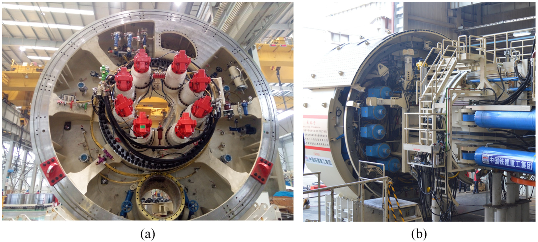
Cutterhead driving systems in different tunnel machines: (a) cutterhead of the shield tunnel machine driven by hydro-motors and (b) cutterhead of the tunneling boring machine driven by electro-motors.
For the overactuated CDS, dynamics of the multi-point gear meshing system should be first studied. The dynamic models with nonlinear time-varying meshing features and spring-damping vibration of bearings were established via various approaches,9,10 the performances with different loads and model parameters were studied via simulation, 11 and new algorithms like Newmark were introduced to accelerate solving. 12 Subsequently, based on Floquet–Lyapunov theory, the parameters that may affect the load sharing behavior and system stability, such as meshing frequency, bearing stiffness, and the variation amplitude of meshing stiffness were also studied.13,14 For the torque synchronization control of rigidly connected driving sources, the work pressures of hydro-motors (HMs) in STM are nearly identical with parallel oil pipes, so efficiency improvement with specific displacements under different load and speed conditions is mostly concerned, 15 and the existing pressure control researches on tunnel machines were commonly for cylinders in the open-type system. 16 For EMs in TBM, the torque master–slave strategy (TMSS) is a practical solution for torque synchronization and was investigated against impact load via simulation. 17 A torque allocation technique was also proposed, the required torque for the speed loop of cutterhead was calculated by adaptive robust control and then allocated to each EM, and the simulated performances of both speed tracking and torque synchronization were significantly improved compared with speed parallel or master–slave strategies. 18 Meanwhile, TMSS could be modified by loop coupling strategy for better load sharing performance, which was validated on a mini CDS rig. 19
The studies analyzed above are mainly deep mechanism studies or advanced control of existing CDS, which are of great value to system improvement. However, the off-stuck of CDS is also of equal importance but rarely studied. This article presents torque synchronization control between HMs and EMs of different mechanical features to accelerate or restart cutterhead in fault zones. For this purpose, a novel half closed-type pump–motor system is designed to control HM like slave electro-motor (SEM) under TMSS, and the hybrid CDS is established on a Φ2.5 m TBM test rig in the upcoming chapter. Based on the modeling of proportional overflow valve (POV) and variable displacement pump (VDP), compound controllers for work pressure and pump displacement to track torque and speed of a main electro-motor (MEM) are proposed in the next chapter respectively. Subsequently, the hybrid CDS is validated to drive cutterhead for acceleration and off-stuck purposes under different speed and load conditions. Finally, conclusions are summarized.
The operating principle of the novel cutterhead hybrid driving system
Structure of the experimental platform
Considering the high reliability requirement in tunnel equipment, the newly designed system should be verified before field application. After our co-simulation research, 20 the hybrid driving system is established on the test rig shown in Figure 2 for further experimental verification. A Φ2.5 m scaled TBM is enfolded by a shell structure, which plays the roles of constraint, support, and load simulation by assembled cylinders and load HM. Pump–valve station and electric control cabinets build the automatic control and driving system.

The Ф2.5 m scaled TBM test rig.
As a part of the whole test rig, the mechanical structure of the hybrid CDS and the corresponding load simulation system is shown in Figure 3. Six driving sources, including four variable frequency EMs and two fixed displacement HMs, are installed parallel through the meshing of pinions and gear ring. A universal telescope coupling is used to connect the cutterhead plane and the input axis of the increaser, so the advancing, rotation, and posture degrees of freedom of the cutterhead could be simulated simultaneously. The tooth number of pinions and gear ring are, respectively, 17 and 131, the module is 10, and the pressure angle is 20 degrees. The transmission ratios of reducers are all designed to be 48.3, while for the increaser it is almost 280.

Mechanical structure of the hybrid cutterhead driving system and the corresponding load simulation system.
Cutterhead hybrid driving based on a novel half closed-type pump–motor system
Figure 4 presents the schematic diagram of the hybrid driving system. A personal computer (PC) is used as the upper computer and communicates with the programmable logic controller (PLC), the middle computer, via industry PROFINET Ethernet. WinCC software installed in PC is used as the human–machine interface. An Open Platform Communications (OPC) server is also built so that data transferred by PLC could be accessed by MATLAB for further control and storage. A frequency converter acts as the lower computer to follow the command of PC and control the speed or torque of the connected EM. The operational data of the converter, including the real-time torque, current, and the speed signal from the encoder, can also be read by PC via the Ethernet, while the inner communication between converters is realized by high-speed optical fiber. Considering that there has not been an accurate and brief load model for TBM, POV and proportional direction valve (PDV) are separately used to simulate the constant and viscous load characteristics.
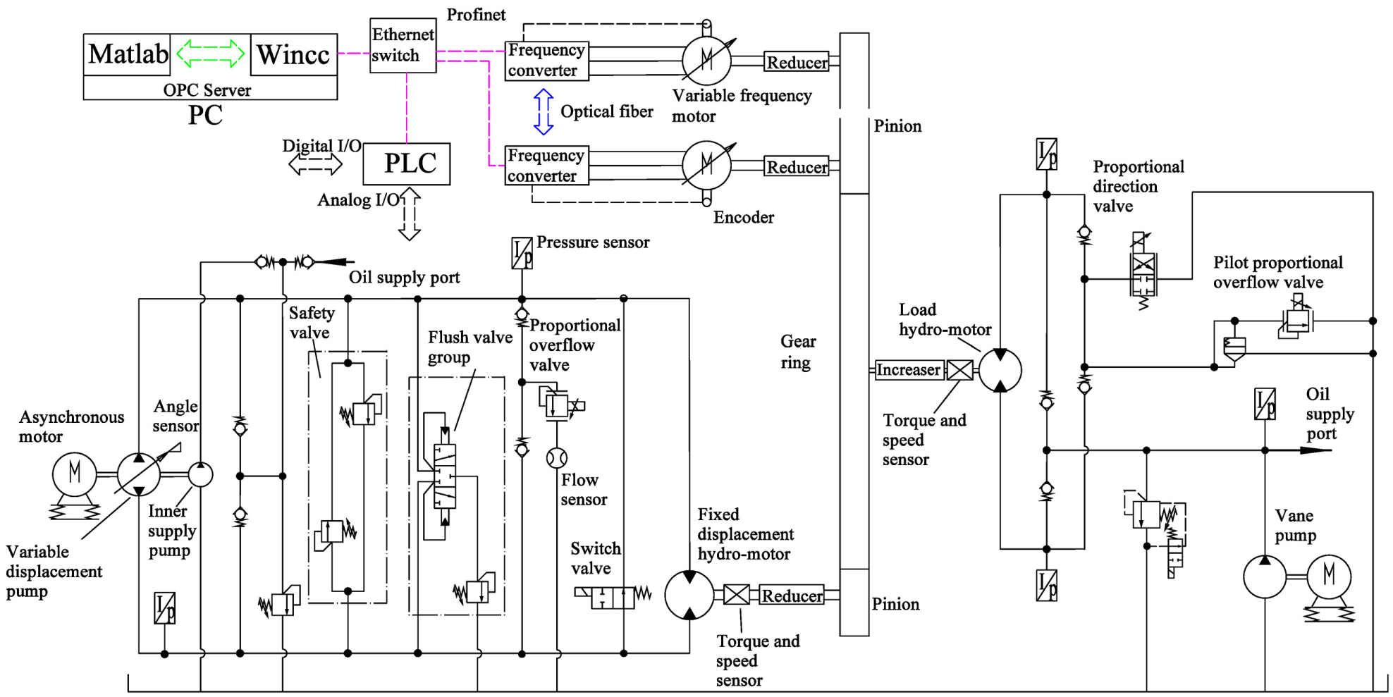
Schematic diagram of the proposed cutterhead hybrid driving system and the load simulation system.
Vector control is a mature solution for speed or torque control of variable frequency EM.
21
According to our latest study on the dynamics of traditional CDS, TMSS could realize torque synchronization against disturbance and parameter deviations between redundant EMs, but the system vibration at the meshing frequency is evitable due to the radial component of pinion meshing force.
22
The simplified structure of TMSS is shown in Figure 5, only the speed of the first EM (MEM) is controlled to track target speed

Simplified schematic diagram of torque master–slave strategy.
Note that the HMs are also parallelly connected around the gear ring like the SEMs and are of minority, so they should be controlled as followers to track the torque of MEM with adaptive speed and flow, and the work pressure with faster response and lower disturbance should be controlled instead of displacement. Thus, a novel half closed-type pump–motor system is designed adding a POV for pressure and torque control and VDP is also used to suit target speed. Instead of the mechanical clutch with strong conjunction impact, large-diameter switch valve parallelly connected between two oil ports of HMs is used to switch the operation modes of CDS and absorb the impact. To be exact, when the load is within the capacity of EMs, HMs are short connected by the switch valve and the VDP does not work (Mode 1), and TBM could work at a relatively high rotation and advancing speed to improve the excavation efficiency. When TBM needs to go through fault zones or restart from jammed condition but the load tends to exceed the capacity of EMs, VDP starts to work at the displacement corresponding to the expected speed and overflow, switch valve shuts off after pump is stable, and POV is enabled to regulate HMs to track the torque of MEM (Mode 2). Driving HMs of fixed displacement are used in the test rig for cost consideration; for further field application, variable HMs are recommended to reduce the flow waste through the switch valve in Mode 1 with minimum displacement. The parameters of key control and monitor components are listed in Table 1.
Specification of key components of the experimental system.

PLC: programmable logic controller; HM: hydro-motor.
Modeling and control of the novel half closed-type pump–motor system
According to previous analyses, the theoretical overflow pressure controlled by the POV, which is also the higher pressure of the half closed-type pump–motor system, should be specified as

where pB is the lower pressure supplied by the oil pump within VDP, λ ≥ 1 is the expected load sharing ratio of HMs compared with MEM, TMEM is the torque of MEM, VHM is the displacement, and ηmHM is the mechanical efficiency of driving HMs. For direct-acting overflow valve, the pressure regulation characteristic is badly affected by the overflow and pressure, so a two-stage POV is selected in Table 1. Figure 6 depicts its simplified schematic structure, and the pressure drop of the irregular orifice Rc with specific flow qc is defined as

where mm, Am, Bm, and dm are separately the equivalent mass, area, damping coefficient, and displacement of the main stage, respectively, pc is the pressure of the spring chamber, km is the spring stiffness, and Fp is the preload spring force. When neglecting the spring and dynamic force changes due to the motion of the main stage, p(Rc, qc) could be assumed as a fixed value decided by Fp alone. Subsequently, qr is nearly equal to qc with qd → 0, and the pressure drop p(Rr, qr) of the orifice Rr is also approximately fixed. Neglecting the dynamic characteristics of the pilot stage, pA finally satisfies

where Ar is the acting area of the pilot stage, Fe is the electromagnetic force, and pr = Fe/Ar is the pilot pressure. Now pA in stable condition is roughly proportional to the control signal after proper dead-band compensation of the almost fixed pressure drops at orifice Rc and Rr. Meanwhile, the open-loop dynamic accuracy is affected by the main overflow and target pressure, which would result in displacement variation of the main stage and consequent pilot flow change.

Equivalent schematic structure of the two-stage proportional overflow valve.
Considering that the target pressure is decided by the load and sharing ratio and is always changeable, the overflow should be stabilized, so the expected displacement of VDP is specified as
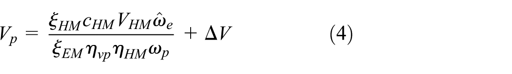
where cHM is the amount of driving HMs, ωp is the fixed speed of VDP, ηvp and ηHM are the volume efficiencies of pump and HMs, and ξEM and ξHM are the transmission ratios of the reducers of EMs and HMs, respectively. Fixed ΔV corresponds to the expected overflow within the rated range of POV, so the linear pressure regulation characteristic of POV could be furthest guaranteed.
For the selected VDP, its inner structure shown in Figure 7 is of typical displacement direct feedback type. Regardless of the dynamics of the pilot cylinder, its displacement proportionally controlled by the inner proportional relief valve should be

where ks is the spring stiffness, Aps is the acting area of the pilot cylinder, and psn and psp are the pilot pressures acting separately in the opposite quadrants. Obviously, x is also the spool displacement of the inner PDV, and the displacement of the valve body is equal to the displacement of the main cylinder y, so the open degree of the inner PDV is (y – x). Based on Laplace transformation for this symmetrical valve–cylinder system, the final transfer function between x and y could be easily derived as

where y is proportional to the swash-plate angle and Vp, Kq is the flow gain of inner PDV, Kc is the flow pressure coefficient, Ctp is the total leakage coefficient, Kce = Kc + Ctp, Ap is the acting area of the main cylinder, mt is the equivalent mass of the main cylinder and swash-plate assembly, Bp is the damping coefficient, FL is the equivalent load force, kp is the spring stiffness of the main cylinder, V is the equivalent volume, and Be is the elastic modulus. For this high-order system with multiple unknown parameters, model-based advanced control is really hard to achieve, and the angle sensor of the swash-plate is of low resolution. Fortunately, according to equation (4) the accuracy demand in pump displacement regulation is quite tolerant because the POV has a wide overflow range. Thus, an approximate form could be derived from equations (5) and (6) neglecting the dynamics of VDP

which means that the stable displacement of VDP is also approximately proportional to the control signal after dead-band compensation of FL, just like POV.

Inner structure of the displacement regulation system of the pump.
Now the expected work pressure of driving HMs and displacement of VDP are derived and are both roughly proportional to the control signal with inner mechanical feedback, and thus the corresponding feed-forward control signals could be designed according to the linearity and dead-band of POV and VDP, respectively. To eliminate the error occurred within POV and VDP due to electromagnet hysteresis and valve dynamics, the feedback controller should also be introduced. Considering the hardware capacity and system complexity, a classical proportional and integral separated controller is established. 23 A large integral factor will not act until the tracking error e is within the preset bounds, so faster and more accurate tracking could be achieved without the risk of overshoot. The structure of the designed compound controller is shown in Figure 8, where kP and kI are, respectively, the proportional and integral parameters and D(e) is the integral separated function satisfying


Structure of the proposed compound controller.
Obviously, this structure is suitable for both overflow pressure and pump displacement regulation utilizing different parameters.
Experimental research
Cutterhead hybrid driving for acceleration application under variable load and speed conditions
In this section, the hybrid driving system is utilized to accelerate the cutterhead against variable loads simulated by POV for higher excavation efficiency, and the load signal is scaled from the common field data. Two EMs and two HMs under TMSS are used and the control loop rate of PLC is 30 ms, so does in next section.
MEM first accelerates from the initial 150 to 450 r/min within 5 s to prepare for the first-stage excavation, as shown in Figure 9. VDP is started in the beginning with the expected displacement of 46.6 mL/r at the first stage, as shown in Figure 10. The switch valve is cut off at 16 s; however, effected by the long tube and valve dynamics, almost 1.5 s is essential for HMs to build 1.5 times torque of MEM, as shown in Figure 11, so the switch valve should be cut off few seconds before the thrust cylinders accelerate. The conjugation brings inlet pressure overshoot of driving HMs in Figure 12 and the corresponding MEM speed overshoot with load drop, and the outlet pressure of driving HMs, which is the overflow pressure of the inner supply pump, has a slight drop with part flow back to the tank through the POV. Then MEM accelerates to 750 r/min for 40–50 s with HMs proportionally sharing the load, and the pump displacement also increases to 64.3 mL/r simultaneously to supply enough oil for the second-stage excavation. With more flow through the load HM, similar pressure drop also occurs to the vane pump. Slow response of pump displacement brings overflow oscillation in the acceleration process, as shown in Figure 13, and the overflow is also unstable under fixed speed condition due to the poor resolution of the swash-plate angle sensor. The switch valve is connected at 80 s, MEM starts to decrease, and the pump displacement also decreases to almost zero. Finally, the experiment ends at 90 s.
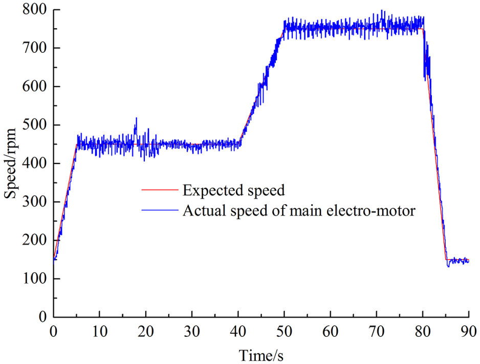
Speed of the main electro-motor in acceleration application.

Tracking performance of pump displacement in acceleration application.

Torques of electro-motors and hydro-motor in acceleration application.

Pressures of load and driving hydro-motors in acceleration application.

Overflow in acceleration application.
Two EMs under TMSS have good torque synchronization performance against varying speed and load, as shown in Figure 11. Considering the large rotation inertia and the diversity between different driving sources, the speed response is also acceptable. With the compound pressure controller, HM could track 1.5 times MEM torque with a maximum error of ±15.2 N m against system vibration. Specifically, the tracking performance under normal load and fixed speed condition (50–65 s) is as good as a mature converter, as shown in Figure 14. However, caused by a larger control period, the tracking error of HM at the moment of conjugation (17–23 s) and heavily decreasing load (68–72 s) is larger than SEM; the overflow fluctuation during the acceleration procedure also generates an adverse impact to the tracking performance of HMs.
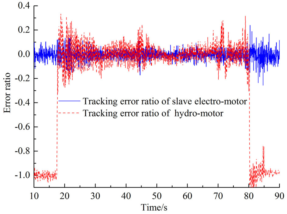
The comparison of tracking error ratios of the slave electro-motor and hydro-motors.
Cutterhead hybrid driving for off-stuck application against different load features
In order to simulate cutterhead off-stuck with the help of HMs, EMs need to work in a locked condition for a while. The temporary current would be 1.5 times the rated value and the power factor is nearly zero, which means that the input power is totally converted into heat and may bring unrecoverable damage to EM without efficient cooling. Natural cooling is clearly inadequate, and a specific water cycle cooling system is disposed in field application for this situation. In order to simulate the locked condition safely in the test rig with the independent cooling fan of EM, the maximum output torque of EM is manually limited to be 40% of the rated value by the converter to decrease the current and heat power. Meanwhile, the load is first regulated by PDV to simulate the viscous load characteristics in soft soil, so cutterhead may not work at expected safety speed but would not be strictly jammed. Since all preceding off-stuck processes were achieved by manual work without data storage, the off-stuck load signals in this section are manually designed.
With limited torques shown in Figure 15, EMs could not reach the expected minimum safety speed of 150 r/min until the switch valve shuts off and HMs begin to supply duple torque of MEM, as shown in Figure 16, and the conjunction brings large speed overshoot to the jammed MEM. After off-stuck, the load pressure shown in Figure 17 decreases from 18 to 23 s and brings a consistent load drop of proportionally regulated EMs and HMs. Then MEM accelerates to 300 r/min for higher excavation efficiency and the pump displacement also increases from initial 22.2 to 31.0 mL/r, as shown in Figure 18, bringing overflow oscillation shown in Figure 19 and viscous load increment shown in Figure 17. Subsequently, the load decreases from 35 to 40 s again and is finally within the capacity of two EMs alone at 300 r/min. Thus, the switch valve is short connected at 42 s and cutterhead speed could be maintained after the impact. Finally, MEM decelerates to 150 r/min from 45 to 50s and cutterhead is unloaded at 50 s, EMs stop at 53 s, and the experiment ends at 55 s. The pressures of the inner supply pump and vane pump both have similar responses as in previous section.

Torques of electro-motors and hydro-motor in off-stuck application against viscous load.

Speed of main electro-motor in off-stuck application against viscous load.

Pressures of load and driving hydro-motors in off-stuck application against viscous load.

Tracking performance of pump displacement in off-stuck application against viscous load.

Overflow in off-stuck application against viscous load.
The cooling efficiency of the forced air system is inversely proportional to the circumstance temperature, so the off-stuck experiment with static friction simulated by POV is also carried out in cold winter of north China to restart the strictly jammed cutterhead. Caused by the limited torque capacity, MEM decreases to nought as long as the backlash of the gear transmission system is overcome and EMs are rigidly connected with the cutterhead, as shown in Figure 20. The cutterhead could be restarted with HMs supplying the double torque of MEM, as shown in Figure 21. The time settings under the two load conditions are identical, so the other responses such as pump displacement and overflow are also similar. This hybrid CDS is proved to be able to restart the jammed cutterhead and is of significant field application value, and the torque tracking error of HMs is within ±13.2 N m.

Speed of the main electro-motor in off-stuck application against static load.

Torques of electro-motors and hydro-motor in off-stuck application against static load.
In the off-stuck process at 150 r/min, at least two four-pole EMs of 15 kW are needed to generate equal torques as HMs, while for the hybrid system the pump driving EM only needs to be 7.5 kW to drive two HMs and supply adequate overflow. Hydraulic transmission has shown significant advantage in low-speed and high-torque application to supply equal torque with 25% assembled power.
Conclusion
A novel CDS of high torque capacity is proposed in this study with EM and HM hybrid driving. Based on the experimental results of a Ф2.5 m test rig, the following conclusions can be drawn:
Vector-controlled EMs under TMSS have good torque synchronization against variable loads and speeds. This phenomenon should be referenced to the control HMs as torque followers with adaptive speed and flow.
With the compliance of POV, the novel half closed-type pump–motor system has high tolerance to the inevitable control error of pump displacement and speed vibration under TMSS.
With the compound controller including model-based feed-forward and integral separated feedback, the torque synchronization performance of HM could approach SEM under normal load and fixed speed condition, and the tracking error is within ±15.2 N m against load change and system oscillation.
The hybrid CDS could restart the jammed cutterhead with HMs supplying double torque of EMs, and the required assembly power is only 25% of EMs.
The proposed hybrid CDS could accelerate or restart the jammed cutterhead in abominable stratum conditions, which will certainly improve the excavation efficiency and help pass the high-risk region quickly. In the future, the performance of the system in terms of pump displacement control to reduce the adverse overflow oscillation via POV, and specific coordinated control between HMs and EMs for better torque synchronization and system stability will be studied and improved.
Footnotes
Appendix 1
Handling Editor: Elsa de Sa Caetano
Author note
Tong Liu is also affiliated with The 14th Institute of China Electronics Technology Group Corporation, Nanjing, China.
Declaration of conflicting interests
The author(s) declared no potential conflicts of interest with respect to the research, authorship, and/or publication of this article.
Funding
The author(s) disclosed receipt of the following financial support for the research, authorship, and/or publication of this article: The authors would like to offer their gratitude to the National Basic Research Program of China (973 Program; Grant Nos 2013CB035400 and 2015CB058103) and the National Natural Science Foundation of China (Grant Nos 51675472 and 51521064).