
Abstract
When a low-cost micro-electro-mechanical system inertial measurement unit is used for a vehicle navigation system, errors will quickly accumulate because of the large micro-electro-mechanical system sensor measurement noise. To solve this problem, an automotive sensor–aided low-cost inertial navigation system is proposed in this article. The error-state model of the strapdown inertial navigation system has been derived, and the measurements from the wheel speed sensor and steer angle sensor are used as the new observation vector. Then, the micro-electro-mechanical system inertial measurement unit/wheel speed sensor/steer angle sensor–integrated system is established based on adaptive Kalman filtering. The experimental results show that the positioning error of micro-electro-mechanical system inertial measurement unit/wheel speed sensor/steer angle sensor is 94.67%, 98.88%, and 97.88% less than the values using pure strapdown inertial navigation system in the east, north, and down directions, respectively. The yaw angle error is reduced to less than 1°, and the vehicle velocity estimation of micro-electro-mechanical system inertial measurement unit/wheel speed sensor/steer angle sensor–integrated navigation system is closer to the reference value. These results show the precision of the integrated navigation solution.
Keywords
Introduction
A micro-electro-mechanical system (MEMS) sensor has the advantages of small size, low energy consumption and low price, but it has a large measurement error. 1 The MEMS inertial measurement unit (MIMU) has a wide range of applications in vehicle navigation. The MIMU contains a three-axis accelerometer and a three-axis gyroscope. The estimation of the attitude, velocity, and position of the vehicle can be obtained by integrating the acceleration and angular velocity of the body in the navigation frame. Thus, when the MIMU is used for position estimation, the positioning accuracy is low in a short time and rapidly accumulates with time. The combination of the global positioning system (GPS) and MIMU has been proposed in earlier studies,2,3 which use the GPS to assist the strapdown inertial navigation system (SINS) to obtain the vehicle position, velocity, and attitude information. Then, the information is applied to the vehicle navigation systems, and the MIMU/GPS is currently widely used in common automotive products. However, the GPS signal is easily disturbed and relies on the satellite information signal, which makes the MIMU/GPS system incomplete and not self-contained. There are common automotive sensors, such as the wheel speed sensor (WSS), acceleration sensor (GX, GY), yaw rate sensor (YRS), and steering wheel angle sensor (SAS), which can be combined with the MIMU to improve the navigation system accuracy and reliability. Abdel-Hafez et al. 4 and Yan 5 proposed a method to correct the drift error of the SINS using WSSs. This method can solve the positioning accuracy problem of vehicle navigation systems when the GPS signal is invalid. The experimental results show that the combination of MIMU/WSS can provide more accurate navigation and positioning information when the GPS fails.
Although the SINS can estimate the vehicle speed and attitude, the integral error will appear in the measurement process. 6 A longer duration of time measurement will result in a larger error, and these integral errors cannot be independently eliminated. Therefore, the SAS of the vehicle is used to provide a new measurement to prevent the gyroscope measurement error in the direction of vehicle travel. The SAS is a common vehicle sensor, which was originally used only in the electronic stability program (ESP) of the vehicle; currently, it is used in various electronic control and auxiliary driving systems, such as the electric steering system, adaptive cruise system (ACC), and automatic driving system. 7 Guo, 8 through a simulation experiment, proposed the combination of MIMU, SAS, and WSS individually to provide navigation information for the vehicle and concluded that the MIMU/SAS combination method and MIMU/WSS combination method had an increase in positioning accuracy of 62% and 75% compared with the SINS and both have better combination navigation performance. Salmon and Bevly 9 combined the vehicle dynamics model with the SAS and WSS sensors to obtain similar positioning data to assist the inertial navigation system (INS)/GPS for vehicle navigation and demonstrate that the combination of low-cost sensor and vehicle model based on real experimental data can increase the positioning accuracy for the vehicle.
The usual method of reducing the INS error is to establish the error-state system model first; then, the appropriate observation is found, and the observation equation is established, particularly through the adaptive Kalman filter (AKF) and other data fusion methods to estimate the error; finally, the attitude, speed, and position estimation information are corrected.10,11 The WSS in the real driving environment will produce an error because of vehicle skidding, yaw, and other factors, so the AKF is used to correct the wheel speed in real time in this article. Cheng et al. 12 and Davari and Gholami 13 describe the application of the AKF in the MEMS/GPS vehicle-integrated navigation and underwater vehicle navigation. Sebesta and Boizot 14 proposed a real-time adaptive high-gain extended Kalman filter (EKF) for a quadcopter INS. Adaptive Kalman filtering is a filtering method with suppression filter divergence. On one hand, it can constantly correct the predicted value in the filter calculation process. On the other hand, the AKF can estimate and correct the unknown system model parameters and noise statistics parameters. 15 In this article, this type of filtering method is used to fuse the signal data of the MIMU/WSS/SAS vehicle-integrated navigation system. Compared to the Kalman filter, the system noise and measurement noise matrix are initially fixed or known. The AKF can correct the inaccurate measurement noise in the actual situations, and this method can achieve better navigation performance.
Based on the existing research, this article uses the combination of odometer and INS, that is, the combination system of MIMU/WSS and uses the steering angle measurement as the new observation to construct the MIMU/WSS/SAS-integrated navigation system. This method integrates SAS and WSS into one system, and the measurements of the sensors are used as observations, which can increase the navigation accuracy. The article structure is as follows. The first part introduces the positioning algorithm of the INS. The second part analyzes the error-state model of each sensor. The third part deduces the observation equation of the system and the theory of AKF. The final part verifies the analysis using actual vehicle experiments and draws the conclusions.
Positioning algorithm
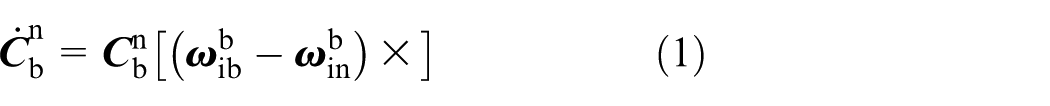
The principle of the SINS is to integrate the angular velocity into the attitude, integrate the acceleration into the velocity, and subsequently integrate the velocity into the position information. The local geographic frame East-North-Up (ENU) is selected as the navigation frame (n frame). The body frame is defined by the vehicle-fixed body frame (the VBF frame (b frame), which is aligned with its longitudinal, lateral, and vertical axes), assuming that the MIMU is exactly located at the center of the vehicle. The acceleration measured by the MIMU is the acceleration of the body frame relative to the inertial frame. The angular velocity is the angular velocity of the body frame relative to the inertial frame. The angular velocity and acceleration are integrated in the navigation frame. The change rates of the attitude, velocity, and position of the vehicle body can be obtained 16 as follows


where

where
Using formulas (1)–(3), we can deduce the equations of the attitude, velocity, and position in the discrete case. When the initial alignment is complete, the current attitude, velocity, and position information of the vehicle can be obtained using the integral operation. 17
Error-state model
In practical applications, it is necessary to estimate and compensate for the errors caused by the accelerometers, gyroscopes, WSSs, and SASs. The error propagation equations of the attitude, velocity, and position in the navigation frame system are expressed as follows


where


Equations (4)–(6) describe the propagation process of the pure inertial system error, and the measurement error should be considered when the WSS and steering wheel sensor are used to assist the navigation system. The speed of the WSS is the product of the angular velocity and the rolling radius of the vehicle tire, and the rolling radius is affected by the ambient temperature and road roughness. Therefore, the error source is the change in scale factor, which is mainly caused by the difference between the rolling radius and the vehicle tire radius. In the calibration process, because the effect of the scale factor is more stable in a short time, it can be used as a constant. We assume that the incomplete constraint of the vehicle is satisfied, and the scale factor error of the WSS is

Ashrafi et al.
18
analyzed the principle and error source of the measurement of the SAS. The measurement error of SAS consists of the following two parts: random error


Through the above analysis, the MIMU/WSS/SAS-integrated navigation system error-state model can be established. The error-state vector contains 18 parameters as follows

The system-state equation is

where
Integrated navigation system
Observation equation
In general, when an MIMU/WSS-integrated navigation system is built, the difference between the measured speed and the calculated inertia using the WSS is used as the measure.20,21 Assuming that the vehicle does not slip and does not leave the ground, the speeds of the vehicle in the lower axis (x-axis) and vertical axis (z-axis) are

The speed measured by the WSS can be converted to the navigation coordinate system using the attitude matrix

where
Extending equation (14) and ignoring the second-order small quantity

According to equation (15), the residual speed between the velocity of the inertia output

where
Using equation (16), the difference between the speed of the vehicle measured by the WSS in frame n and the speed output of the inertial guidance system in frame n is taken as the observation quantity, and the navigation system accuracy can be improved. The measurement error of the SAS does not accumulate over time and can also be used to improve the SINS navigation system accuracy.
Most vehicles are front-wheeled vehicles. When the vehicle turns, the steering wheel angle can be converted into the deflection angle

where s is the scale factor, and
Considering error

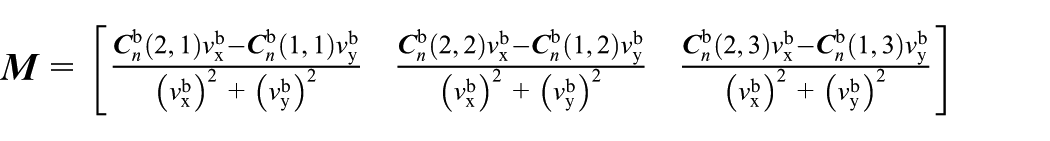
In addition to using the steering wheel angle, the front wheel angle can also be obtained from the speed in the vehicle coordinate system

where
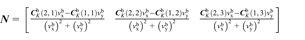
Considering the attitude error

By extending equation (20) and ignoring the second-order small quantity

The observation error

Combining equations (21) and (22), we obtain equation (23)

where

The angle residual can be obtained from equations (18) and (22)

Therefore, with equations (16) and (24), the measurement vector is

Then, the measurement equation is

where
AKF
An AKF is designed to better determine the position, velocity, and attitude of the vehicle. The brief structure of the integrated system is shown in Figure 1. Consider the following linear discrete system

where

Structure of the MIMU/WSS/SAS.
In the conventional Kalman filter, the measurement noise covariance matrix
where
The estimation error and its corresponding covariance accumulate during the propagation stage. The propagated covariance matrix

where
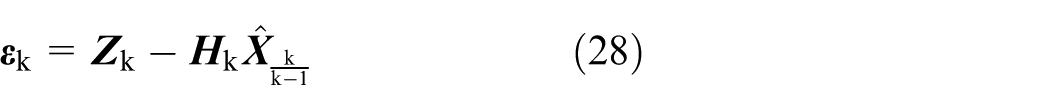
According to the Kalman filter theory,

where
Using the above equations, the measurement noise matrix at time k is

where N is the number of samples.
Then, the measurement noise covariance matrix can be estimated online, and the unexpected bias on the odometer and electric compass can be detected.
In the MIMU/WSS/SAS-integrated navigation system, the MIMU measures the acceleration and angular velocity in the body frame at the time of k and updates the attitude, velocity, and position after switching to the navigation frame. Simultaneously, the car ESP system reads the WSS and SAS output, which are converted to the vehicle speed and front wheel angle. The WSS and SAS provide the following two observations for the combined navigation system: (1) the difference in speed of the WSS output and INS output in the n frame; (2) the difference between the wheel angle and the front wheel angle, which is calculated using the inertial output. The AKF calculates the gain matrix by observing the vector and error model and estimates the error to constantly correct the attitude, velocity, and position during the update process. The recursive principle of AKF is shown in Figure 2.10,19

Flow chart of the adaptive Kalman filter.
Experimental testing
To test the accuracy of MIMU/WSS/SAS-integrated navigation system, the actual vehicle experiment was performed. The trajectory of the actual vehicle experiment is shown in Figure 3. A Xiens MTi-30 sensor and Vector CAN bus test equipment were installed on the vehicle, and the installation of each device is shown in Figure 4. MTi-30 is an attitude-heading reference system with an internal integrated tri-axial accelerometer, a tri-axial gyroscope, and a tri-axial magnetometer. The MTi-30 can produce the original data of the accelerometer, gyroscope, and filtered posture information. The MTi-30 performance specifications are shown in Table 1. The Vector bus test equipment includes CANoe, CANcope, and CANStreessDR. In the measurement process, the sampling frequency of MTi is 100 Hz, the sampling frequency of SAS and WSS is 50 Hz, and the frequency of the filter update is 50 Hz.

Path taken by the vehicle.

Installation of the equipment in the vehicle.
Specifications of MTi-30. 20

The MTi-30 determines the vehicle attitude using an accelerometer, a gyroscope, and a magnetometer and removes the magnetic interference of the vehicle before performing the attitude measurement. The attitude of the vehicle in the quiescent state as the result of the initial alignment, latitude, and longitude of the starting position was known, and the height was set to 0 m. The WSS is mounted on the front wheel, and its final output data take the average of the right and left wheel speeds. The SAS was installed in the steering column below the steering wheel with the steering column coaxial installation, and the output data were the steering wheel angle data. The MTi sensor and CANoe were connected to the same computer by USB. The corresponding PC software programs were MT Manager and Vector CANape, respectively. To ensure the synchronization of the sensor measurements, the system time was added to the measured data as the time axis. After the experimental testing, the data are sent to MATLAB for offline simulation, and the experimental results are shown in Figures 5, 6, and 7. During the testing, the total vehicle driving time was 150 s, and the driving distance was approximately 1 km.
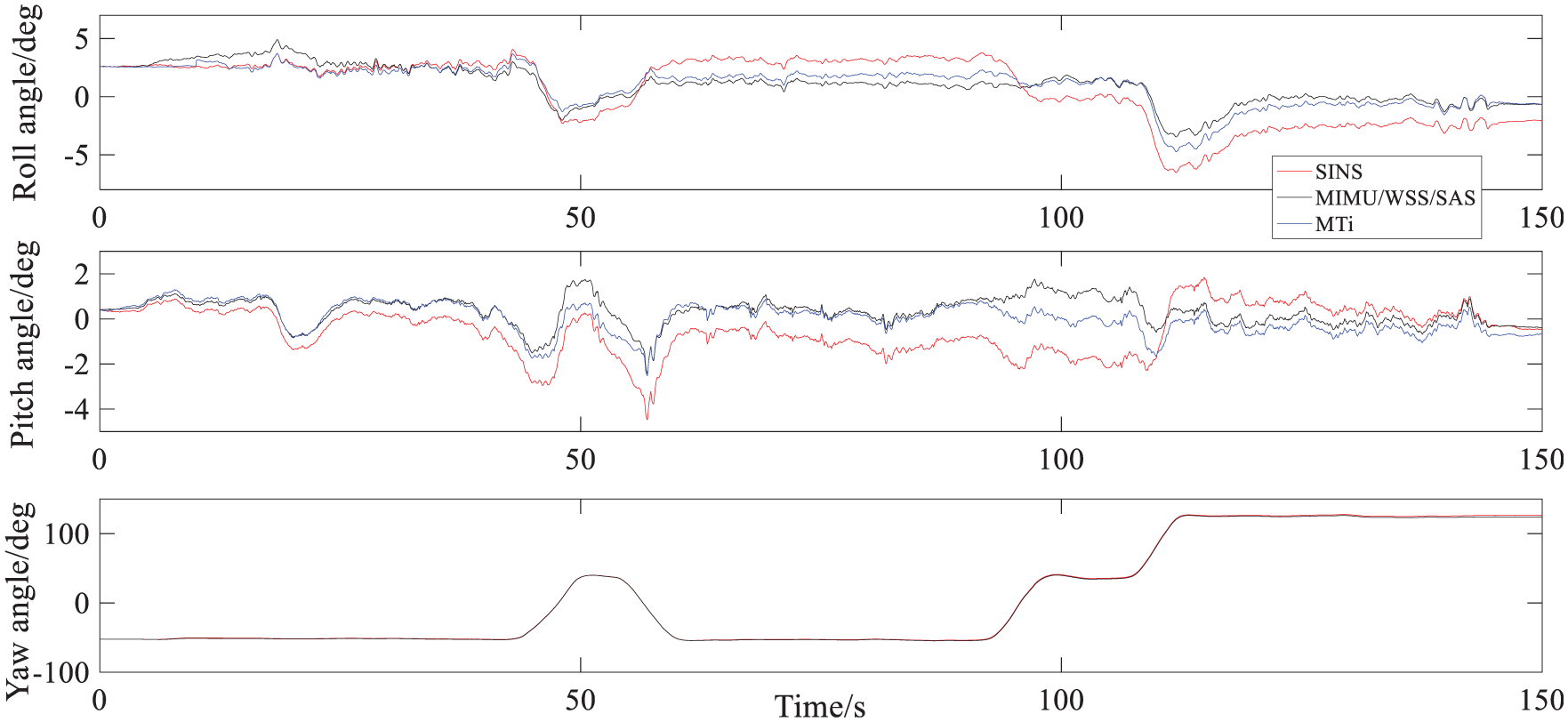
Attitude estimation results of three different navigation systems.

Speed estimation results of different navigation systems.
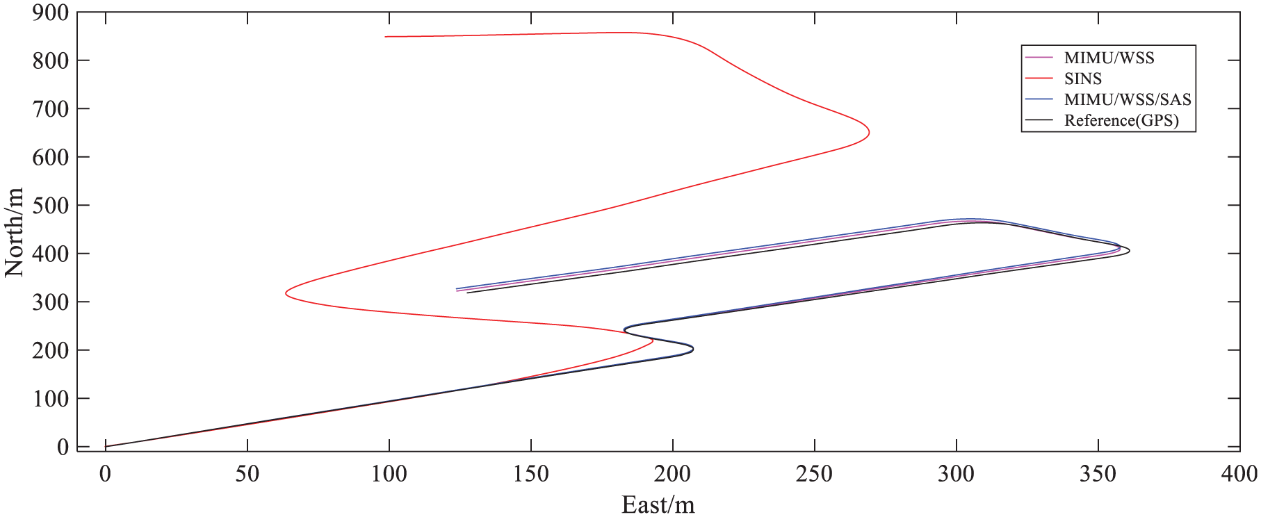
Navigation results of the integrated navigation system.
Figure 5 shows the results of three different navigation modes to estimate the vehicle attitude. The blue line shows the output curve of MTi. The red line shows the vehicle attitude angle output of the SINS. The black line shows the MIMU/WSS/SAS-integrated navigation system to the vehicle attitude estimation results. Table 2 shows the contraction of the absolute value of maximum attitude estimation error in three navigation methods. The results show that the MIMU/WSS/SAS-integrated navigation system can well estimate the vehicle roll angle and pitch angle. The output error is within 0.5° and 1° compared with MTi and SINS, respectively, and the yaw angle of the estimated error is controlled within 1°. The speed estimation results of different navigation systems are shown in Figure 6. The blue line shows the output curve of the GPS, which serves as a reference curve. The red line represents the vehicle speed output of the SINS. The black line shows the estimation of the vehicle speed using the MIMU/WSS/SAS-integrated navigation system. The speed estimation of the MIMU/WSS/SAS-integrated navigation system is clearly closer to the actual value. Hence, the MIMU/WSS/SAS-integrated navigation system has a higher accuracy in the speed estimation; therefore, the navigation and positioning accuracy are improved.
Absolute value of the maximum attitude estimation error.

MIMU: micro-electro-mechanical system; WSS: wheel speed sensor; SAS: steering wheel angle sensor; SINS: strapdown inertial navigation system.
Figure 7 compares the results of the MIMU/WSS/SAS-integrated navigation system data, SINS data, MIMU/WSS-integrated navigation system data, and real path route data. The real path route is measured by the GPS and can be used as a reference route. As shown in Figure 6, the method of using MIMU output data to directly predict the path has better accuracy in the first 20 s. However, because of the accumulated MIMU measurement error over time, rapid divergence appears, which affects its accuracy. Table 3 shows the positioning error using the pure INS and integrated navigation system within 150 s, where the east error rate decreases by 92.25% and 94.67% using the MIMU/WSS-integrated navigation and MIMU/WSS/SAS, respectively, and the error rate increases by 2.42% compared to that without the SAS. Thus, the use of the SAS can effectively improve the positioning accuracy. The north error rate decreases by 98.65% and 98.88% using the MIMU/WSS-integrated navigation and MIMU/WSS/SAS, respectively, compared to that without the SAS; the error rate increases by 0.23%, and the horizon error-reduction rate also increases. Considering the three directions of ENU; the error-reduction rate of MIMU/WSS/SAS is 95.68% higher than SINS, which proves that the MIMU/WSS/SAS can provide more accurate and completely autonomous navigation for vehicles. In addition, the combination of the MIMU/WSS/SAS-integrated navigation mode also improves the positioning accuracy compared to the MIMU/WSS-integrated navigation, which shows that the steering wheel sensor and WSS can assist the INS with better navigation effect.
Positioning error of the MIMU/WSS/SAS.

MIMU: micro-electro-mechanical system; WSS: wheel speed sensor; SAS: steering wheel angle sensor.
Conclusion
When the low-cost INS with the MIMU is used for the SINS, considering the positioning accuracy of such INSs and the fact that the gyroscope cannot eliminate the integral error in the process of using the gyroscope, an MIMU/WSS/SAS-integrated navigation system is proposed in this article. Based on the new observations provided by the sensor, the system error-state model and observation equation are deduced, and the effect of the complex situation on the measurement noise in the actual driving process is considered. The AKF algorithm is designed to integrate the navigation system. This filtering method can estimate the measurement noise in real time, so it can correct the data in the navigation process in real time and realize online estimation. The real vehicle experiment shows that the MIMU/WSS/SAS-integrated navigation system can provide higher positioning navigation accuracy than the INS and the integrated navigation method of odometer and INS. The WSS and SAS are the necessary sensors for the vehicle ESP and other systems compared to the GPS, which has the disadvantages that the signals are vulnerable to block and shield. Such sensor information is completely independent of the information source; therefore, the proposed method of the integrated navigation system can provide better vehicle status estimation and navigation information for the vehicle autonomous navigation, unmanned systems, anti-collision systems, and so on.
Footnotes
Handling Editor: António Mendes Lopes
Declaration of conflicting interests
The author(s) declared no potential conflicts of interest with respect to the research, authorship, and/or publication of this article.
Funding
The author(s) received no financial support for the research, authorship, and/or publication of this article.