
Abstract
The sensitivity of key structural parameters to the hydraulic response characteristics in an electronic fuel injector is investigated. First, the hydraulic response characteristic is defined in detail (the opening/closing delay and the opening/closing time). Second, the key structural parameters influencing the hydraulic response characteristics are derived. Finally, the importance and effects of key structural parameters on hydraulic response characteristics are examined, by using the design of experiments method and the range analysis. Results show that the fuel inlet passage diameter is the primary influencing factor to the opening delay and closing delay, while the control piston diameter has the dominant effect on opening time and closing time. A small opening delay and a small opening time prefer a little fuel inlet passage diameter and control piston diameter; however, they contribute to a large closing time and closing delay. The fuel outlet passage diameter is the secondary influencing factor in opening delay, but the second factor that affects the opening time is the diameter of needle.
Introduction
With the depletion of fossil fuels and the growing environmental problem, diesel engines’ performance and emissions attract more and more attentions. Among the components of modern diesel engine, the high-pressure common rail (HPCR) system is the core, which is aimed at enhancing fuel burning and at optimizing NOx and particulate matter (PM) engine-out emissions, as well as fuel consumption and combustion noise.1–4 As the most complex core component of HPCR system, the performance of electronic fuel injector directly affects the performance and emission of diesel engine. Therefore, so many investigations pay attention to this field, by using one-dimensional (1D) simulation analysis method.5–11
The structure parameters of electronic fuel injector can affect the performance of the whole HPCR system, thereby affecting the performance of diesel engine. Therefore, many researchers have carried out a lot of research work around the structural parameters of electronic fuel injector.12–20 These studies focus on the nozzle area. The effect of nozzle hole arrangements and structural parameters on the performance of the electronic fuel injector is discussed. The hydraulic response characteristic refers to the opening and closing speed of the injector needle valve and represents the rapidity of the response of the electronic fuel injector. It is an important index to evaluate the performance of electronic fuel injector. Many of the research performed on hydraulic response characteristic in HPCR system have dealt with the fuel properties (fuel density, volume modulus and viscosity) and temperature.21–23
However, few studies have mentioned the relationship between structural parameters and hydraulic response characteristics of electronic fuel injector in the literature. Hu et al. 24 defined the hydraulic response as opening delay and closing delay and built a complete and detailed one-dimensional (1D) model of the electronic fuel injector, which integrated into an optimization model. They pointed out that the control piston diameter, fuel inlet passage diameter, fuel outlet passage diameter and their interactions are influential factors to the opening delay, while the fuel inlet passage diameter has the dominant effect on the closing delay. Jia et al. 25 focused on some of the structural parameters of the control valve in injector. Their research showed that these key structural parameters of the control valve, such as the diameter of the feeding orifice, the diameter of the discharge orifice and the hole diameter of the fuel diffusion hole, had a great influence on the establishment of the control chamber pressure and the action of the needle valve. Within a certain range, when the control chamber volume was small, the control chamber pressure changes rapidly, the needle moves quickly and the system responds quickly.
In this article, the relationship between structural parameters and hydraulic response characteristic has been investigated in more detail. First, the hydraulic response characteristic is defined by four key time points in the course of needle valve movement. These four key time points are the valve opening delay, the valve opening time, the valve closing time and the valve closing delay. Second, the key structural parameters influencing the hydraulic response characteristic are derived, which is according to the hydraulic response control equation of the electronic fuel injector. If the electric fuel injector is regarded as a system, the key structural parameters are taken as the input of the system and the hydraulic response characteristics are taken as the output of the system. The relationship between hydraulic response characteristics and key structural parameters is thus constructed. Next, a one-dimensional (1D) electronic fuel injector model is built with AVL-Hydsim and is validated with injection rate data. Then, the sensitivity of hydraulic response characteristics of injector to every key structural parameters is studied. On this basis, the test scheme is established by using the design of experiments (DOE) method. The parameter sensitivity calculation formula is given by introducing the method of range analysis. Through parameter sensitivity, the influence order of the every key structural parameters on the hydraulic response characteristics is shown.
Definition of hydraulic response characteristic
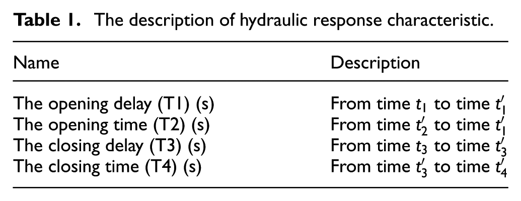
The injector hydraulic response characteristic refers to the needle valve opening/closing delay and needle valve opening/closing time. Theoretically, hydraulic response refers to the time of the displacement of the needle valve and control signal time difference, but the electromagnetic valve response itself has lag; therefore, in this article, hydraulic response is defined as shown in Figure 1 and Table 1.
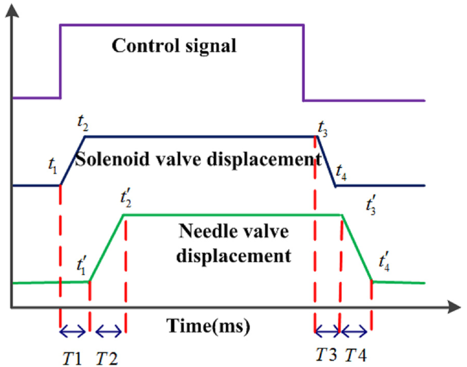
Schematic diagram of the definition of the hydraulic response.
The description of hydraulic response characteristic.
The key structural parameters
The hydrodynamic equation of the electric fuel injector is expressed as
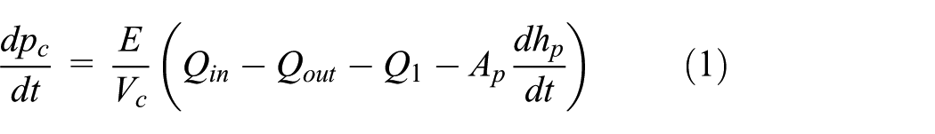


where


In which
According to the hydraulic response control equation (equations (1)–(8)) of the electric fuel injector, it can be seen that the key structural parameters of the hydraulic response are the IPD, OPD, CPD and DN, which can be seen in Figure 2. The opening and closing of the electric fuel injector depend on the pressure difference between the control chamber and the accumulation chamber.

The structure diagram of injector.
If the electric fuel injector is regarded as a system, the key structural parameters are taken as the input of the system and the hydraulic response characteristics are taken as the output of the system, and then, the relationship between the system input and output is shown in Figure 3.

Relationship between the key structural parameters and the hydraulic response in injector.
Simulation conditions and model validation
The injector model can be built either by a set of ordinary differential equations or some advanced tools, that is, AVL-Hydsim and AMESim software. In this article, the fuel injector simulation model was built in AVL-Hydsim software, as shown in Figure 4, and its main parameters are shown in Table 2. The model includes nozzle, needle valve, control piston, control chamber, two orifices, sump, solenoid valve and the leak of needle valve and control piston.
The main parameters of injector.

In this model, some assumptions were made: (1) all the variations are isothermal, and therefore, the fuel temperature and the fuel properties were assumed to be constant along the injector and equal to those at the injector inlet; 10 (2) the pressure feeding the model is constant; therefore, it ignores the pressure fluctuations caused by the cyclical oil supply from the high-pressure pumps. 21

One-dimensional fuel injector model.
The model was validated with the experimental injection rate of 160 MPa rail pressures. Figures 5 and 6 represent the principle of fuel injector test system and the experiment environment, respectively. Figure 7 shows the comparison of the injection rate between experimental and simulation. In the process of opening and closing the injector, the injection rate curves of simulation and experimental coincide. In the intermediate stages of injector opening, there exist a little error in the simulation curves and experimental curves. The average relative error is 5.2%. The main reason is the simulation model directly takes the model of the injector rail pressure as constant pressure of 160 MPa and does not consider the rail pressure fluctuations. The injector dynamic response is mainly decided by the injection rate slopes, so these tiny differences in the injection rate can hardly have an impact on it.10,21

Systematic configuration of injector test system.
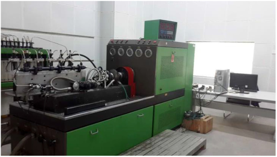
Experiment environment.

Model validation.
Results and discussion
Influential factor analysis
The mathematical expression between the input and output of the system can be expressed as

The relationship between system output and input can be written as

When the input of system changes slightly

The output of the system is considered as

The system output Taylor series expansion form is
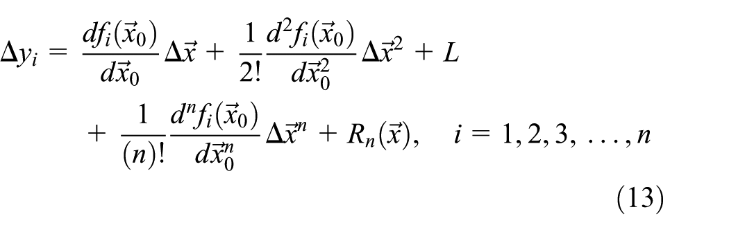
So, the sensitivity

When
The system output is affected differently by each input of the system; therefore, this article first analyses the system output sensitivity on a single input. It means only one input is changed at a time, while other inputs are kept constant. At the same time, in order to better display the change rule of the system output

The relationship between system output and changes in a single input can be seen from Figure 7.
The IPD mainly affects the fuel volume of the oil injector. When other parameters remain the same, a larger IPD can inject a larger amount of fuel into the injector after the solenoid valve is opened. As a result of the oil outlet discharge rate remains the same, the pressure reduction rate of the control chamber is lower than the small IPD, which increases the time of the control chamber pressure to be reduced to the critical pressure of the needle valve opening and decreases the time of the control chamber pressure to be increased to the critical pressure of the needle valve closing. So, the opening delay will be increased, and the closing delay will be decreased. At the same time, a lower pressure reduction rate in control chamber will reduce the acceleration of the needle valve in the process of needle valve rising, which will augment the acceleration of the needle valve during needle valve descent. Therefore, a larger IPD can enhance the opening time and weaken the closing time. Proof can be seen in Figure 8(a). T1 and T2 are sensitive to the positive direction of the IPD; however, T3 and T4 are sensitive to negative direction. It can be seen from the sensitivity value that T1 and T2 are more sensitive to the increase in the IPD than the decrease in the IPD, but T4 is the opposite of T1 and T2.

The variation rule and sensitivity of hydraulic response characteristics are affected by (a) the IPD, (b) the OPD, (c) the CPD and (d) the DN.
The OPD mainly affect the control cavity pressure relief capacity. A larger OPD means more fuel can be discharged from the control chamber at the same time, ceteris paribus. Therefore, compared with the small OPD, a larger OPD can reduce the pressure in the control chamber to the opening pressure of the needle valve in a short time. It also increases the acceleration of the needle valve during the rising process. So, for a larger OPD, the opening delay and the opening time will be reduced. The closing process of needle valve is not affected by the OPD. So, it does not affect the closing time and closing delay. These can be seen in Figure 8(b).
The CPD mainly affects the top surface area of the control piston, and a larger CPD means a larger pressure force being exerted on control piston. Since the pressure force working on the lower part of the needle valve remains the same, when the solenoid valve is energized, the needle valve is subjected to a smaller net force during lifting. However, it is exactly this net force that causes the needle valve to move upwards to start fuel injection. In this condition, the smaller net force surely slows up the needle valve opening velocity and climb acceleration. When the solenoid valve is deactivated, a larger opposite net force pushes the needle valve downwards, which promoted the needle valve closing velocity and descending acceleration. So, a larger CPD can result in a longer opening delay and opening time and a shorter closing delay and closing time. The sensitivity of needle valve opening process to the CPD is higher than that of closing process. Proof can be seen in Figure 8(c).
The DN mainly affects the stressed area of the lower part of the needle valve, and a larger DN will increase the critical pressure of opening/closing of the needle valve. In the solenoid valve opening stage, the time for the pressure in the control chamber to drop to the critical pressure of the needle valve opening is reduced. However, in the solenoid valve, closing stage is the opposite. A larger DN will increase the acceleration during the rising process of the needle valve and reduce the acceleration during the falling process of the needle valve. So, a larger DN can result in a longer closing delay and closing time and a shorter opening delay and opening time. Proof can be seen in Figure 8(d).
Parametric sensitivity analysis
The previous work has studied the sensitivity and variation rule of system hydraulic response characteristics to each key structural parameter of the system, which is a qualitative analysis. In any process or experiment, there are a finite number of parameters which define the output of the system. The influence of each parameter on the output is different. Therefore, it is necessary to quantitatively analyse the relationship between response characteristics and key structural parameters of the system. It can be achieved by studying the combination of key structural parameters that affect the hydraulic response characteristics of the system. For four key structural parameters, with five levels each,
The range analysis was carried out for the test results, and the parameter sensitivity relation between the system hydraulic response characteristics and the key structural parameters was deduced.
The range of system output

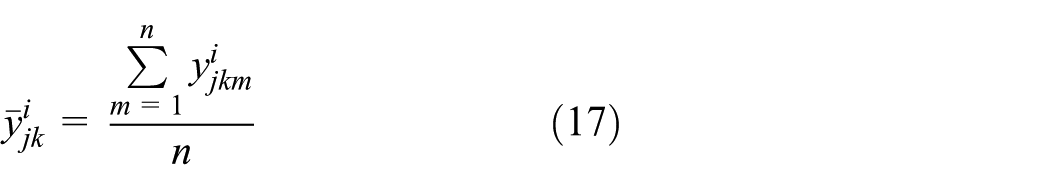
In which
The parameter sensitivity relation between the system hydraulic response characteristics and the key structural parameters can be expressed as

where
From Figure 9(a), it can be clearly seen that a small IPD, a small CPD, a big OPD and a big DN bring about a short opening delay. However, small DN, small OPD, large CPD and IPD increase the opening delay dramatically. This means that the opening delay is sensitive to the positive direction of the IPD and CPD, which is sensitive to the negative direction of the OPD and DN. The degree to which key structural parameters affect the opening delay:

(a) The parameter sensitivity of opening delay to the key structural parameters. (b) The parameter sensitivity of opening time to the key structural parameters. (c) The parameter sensitivity of closing delay to the key structural parameters. (d) The parameter sensitivity of closing time to the key structural parameters.
Figure 9(b) shows that a small opening time is achieved with a small IPD, a small CPD, a large OPD and a large DN. And it shows that the opening time is sensitive to the positive direction of the IPD and CPD, which is sensitive to the negative direction of the OPD and DN. In terms of the magnitude of the impact,
The closing delay is sensitive to the positive direction of the DN, and it is sensitive to the negative direction of the IPD and CPD, as shown in Figure 9(c). A small IPD, a small CPD and a big DN together lead to increase the closing delay. The same is true for closing time in Figure 9(d).
The main sequence of the influence of the key structural parameters of the electronic fuel injector on the hydraulic response characteristics is shown in the following
The opening delay: IPD > OPD > CPD > DN;
The opening time: CPD > DN > IPD > OPD;
The closing delay: IPD > CPD > DN > OPD;
The closing time: CPD > IPD > DN > OPD.
Conclusion
The above research focuses on the sensitivity of the hydraulic response characteristics of the electric control injector to the key structural parameters. The hydraulic response characteristics of the electric fuel injector (opening/closing delay, opening/closing time) are defined. The key structural parameters are obtained according to the control equation of the electric control injector. The key structural parameters and hydraulic response characteristics are regarded as the input and output of the electric control injector system, respectively, and the relationship between them is constructed. Then, a numerical simulation model of the electric control injector was built using AVL-Hydsim software, and it is validated with the experimental injection rate. The sensitivity of hydraulic response characteristics of injector to single structural parameters was studied. The test scheme is designed with DOE method, and the parameter sensitivity calculation formula is given by introducing the method of range analysis, and the parameter sensitivity of the key structural parameters on the hydraulic response is obtained. The main conclusions are as follows:
The most important structural parameters affecting the hydraulic response of the injector are the IPD and CPD. The main structural parameters that affect the opening delay and closing delay is the IPD, but for opening time and closing time, it is the CPD.
Both the valve opening delay and the valve opening time increased with the increase in the IPD and CPD; however, they decreased with the increase in the OPD and DN. These are sensitive to the positive direction of the IPD and CPD, which is sensitive to the negative direction of the OPD and DN. The closing delay and closing time are reversed.
The OPD is one of the main influencing factors for opening delay. However, it is significantly weaker than the other structural parameters for the opening time, closing delay and closing time.
The opening time is more sensitive to DN than the closing delay and closing time. The sensitivity of the opening delay to the DN is minimal in the key structural parameters.
Footnotes
Handling Editor: Anand Thite
Declaration of conflicting interests
The author(s) declared no potential conflicts of interest with respect to the research, authorship and/or publication of this article.
Funding
The author(s) received no financial support for the research, authorship and/or publication of this article.