
Abstract
The flow field around supersonic aircraft is usually accompanied by complex flow phenomena, such as shock wave and shock wave/boundary layer interaction, which cause some adverse effects on aircraft performance. Seeking effective flow control methods has been a hot topic for many researchers. As an important method to improve the flow characteristics in supersonic flows, micro jet technology and its control mechanism have been paid much attention. In this article, we used compression corner calculation model and conducted detailed numerical investigations in the supersonic flow field with different injection pressure ratios, various actuation positions, and different nozzle types. The interaction between the micro jets and supersonic upstream flows generates complex flow structures, which contain bow shocks, barrel shocks, Mach disk, counter-rotating vortex pairs, and so on. The flow characteristics with micro jet schemes are superior to those in the no-control case. The controlling performance of micro jet is mainly determined by the following aspects. First, the downwash effect of counter-rotating vortex pairs can bring high-energy fluid into the bottom of the boundary layer to activate low-energy fluid and then strengthen the ability of resisting the flow separations. Second, the bow shock, which is generated upstream of the micro jet, significantly decelerates the downstream flows. Thus, the shock intensity at the corner is weakened and the characteristic of shock wave/boundary layer interaction is improved. In addition, the effective function range of MJ, that is, the distance between the counter-rotating vortex pair and the wall surface, is also an important factor. When both the counter-rotating vortex pairs and the bow shock are further from the wall, the flow characteristics around the corner in a larger area can be improved. Research shows that the micro jet scheme with Laval nozzle gives better controlling effect on shock wave/boundary layer interaction when the injection pressure radio is set to be 0.6, with the actuation location being 20 times the jet outlet diameter upstream of the corner.
Keywords
Introduction
Shock wave/boundary layer interaction (SWBLI) exists in the flow field of transonic, supersonic, and hypersonic aircrafts. It not only increases the air resistance but also induces boundary layer separation and unstable flow instability which will seriously affect the aircraft performance. Although there has been a lot of research conducted for studying the SWBLI, still there are a number of unsolved technical problems for its formation mechanisms and controlling methods.1,2 In recent years, active flow control techniques, for example, micro jet (MJ), and other methods have demonstrated a unique advantage and wild applications because of their good performance under variable working conditions.
MJ technology is based on the chaos theory and the nonlinear complex system instability theory. Initiative microscale disturbances injected on the controlled fluid field obviously influence the macroscale flows. 3 Due to its small outlet diameter, typically from 0.2 to 1 mm, and small stress concentration with low weakened wall strength, it is called MJ. In addition, MJ can also be turned off when it is not necessary and it does not affect the aircraft’s aerodynamic shape.
Early in the mid-20th century, the Australian scholar Wallis and colleagues4,5 began to apply jet technology to control the boundary layer separation which was induced by shock wave and verified that it could suppress flow separation. Due to the limit of experiment conditions and the level of calculation, until the 1980s there was further study of jet control methods, initially mainly for jets with aperture greater than 1 mm. In 1989, the jet was named jet vortex generator by Johnston and Nishi, 6 and he used a 6.35-mm diameter jet in the mainstream with the speed of 15 m/s to experimentally control the flow separations. He suggested that the flow rate ratio exceeding 0.8 reduced the separation size. In this experimental condition, they found that jet with an inclination angle between 45° and 90° produced larger streamwise vortex intensity. 7 Taking into account the spatial arrangement, concentrated stress, and other issues, this kind of jet starts to be micro-oriented and the exit aperture is no more than 1 mm in the 21st century, namely, MJ technology.
Comprehensive study of MJ has been carried out in the subsonic flow field. Low-speed MJ in supersonic flow is easily submerged and cannot work well. Therefore, in this study, MJ with sonic outlet flow is used. Figure 1 shows the interaction between the jet and supersonic flow, 8 including the complex shock structures such as the λ shock wave, bow shock, barrel shock, the streamwise vortexes, and horseshoe vortexes. How does such a complex flow structure influence the downstream SWBLI? Will it bring negative effect on the flow field by adding the MJ? How do we optimize MJ parameters to achieve the best controlling performance? All of the issues mentioned above will be discussed below.

Flow structures within transonic flow field coupled with MJ. 8
Doerffer and Szwaba first put forward vortex, induced by the steady MJ flow, to control the SWBLI.9–11 Experiment has verified that MJ with Mach numbers 1.25, 1.35, 1.45, and 1.35 and 0.5 mm diameter can obviously reduce the size of separation zone and damp the low-frequency oscillation amplitude of shock wave. To further understand the controlling effects of parameters such as the jet angles and diameters, they continue to study the jets effects with 90° pitching angle, 45° yaw angle, 0.5 mm diameter, and 0.8 mm diameter. In their recent study, Szwaba 12 focused on the influence of the vortex generator diameter on the separation region. It presented the results of experimental investigations and provided new guidelines for the design of air-jet vortex generators to obtain more effective separation control. Verma and colleagues13,14 then compared the performance of the vertical jet and inclined jet with 45°. It showed that the vertical jet had better controlling effect on pressure fluctuation in the separation zone than the inclined jet. However, the controlling effect would be weakened by the strong interactions from relatively compact vertical jets. Souverein and Debiève15,16 also showed that the MJ can effectively weaken the separation caused by SWBLI.
In addition to optimizing MJ geometric parameters, locations, and array parameters, there is another important factor called MJ injection pressure. By using the particle image velocimetry (PIV) and background-oriented schlieren technology, Ali et al.17,18 studied the vertical MJ with 0.4 mm diameter and different injection pressure ratios (MJ injection total pressure/flow total pressure) in main flow (Ma = 2 with 24° flat corner). It was found that the increase in injection pressure could move the separation shock upstream and further damp the separation zone pressure oscillations. When the injection ratio increased to 3, the wall pressure fluctuations can be reduced by about 50% in separate area.
Young et al. 19 applied the jet technology to the supersonic inlet flow control. The jet with 1.5% inlet flow in the normal shock bifurcate zone could increase the total pressure by 3.5%, reducing the distortion by 35%. Chen 20 did a relatively comprehensive research about flow direction and pitch and yaw angles and aligned the holes’ effect on SWBLI with MJ. The study found that an increase in injection pressure could improve the controlling effect, but not the higher the better. And it was a pity that the detailed values were not given. Jet position and separation area should maintain a distance to ensure the blending process of the streamwise vortex. When the pitch angle is set to 45°, co-injection MJ with aligned holes has better controlling effect than the reverse MJ.
In conclusion, the MJ aerodynamic parameters, geometric parameters, locations, and array parameters have significant influence on controlling effect; thus, we must carry on with the advanced optimization design. With the aid of comprehensive optimizations of MJ, we can suppress the flow separation, improve SWBLI flow performance, and weaken the pressure oscillations. Although the studies mentioned above verified the MJ flow control measure is promising, the controlling mechanism is not yet clear. In addition, there should be different SWBLI controlling effects with various types of nozzles, such as the convergent nozzle and the Laval nozzle.
Based on the compression corner simulation model, this article studied the performance of MJ with different injection pressures, positions, and nozzle types. The boundary layers and shock waves around the corner in supersonic flow field were analyzed to explore the MJ flow control mechanisms.
The numerical method and validations
The numerical method and case designs
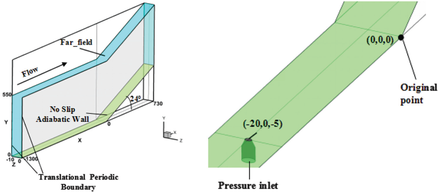
The conventional compression corner is used as the calculation model, which is shown in Figure 2. X is the streamwise direction and Z is the spanwise direction, and all sizes are listed in the figure. There are two forms of MJ: one with the convergent nozzle and the other with the Laval nozzle. The detailed size is shown in Figure 3. MJ outlets are located in different positions upstream of the corner with the injection direction perpendicular to the main flow.
Compression corner with MJ.

Geometries of MJ: (a) MJ with convergent nozzle and (b) MJ with Laval nozzle.
In the simulation, the inlet flow Mach number is 2.9 and the total pressure is 6.8 × 10⁵ Pa. The total temperature is 265 K, with the resulting Reynolds number being 6.5E + 7. The inlet boundary layer displacement thickness is 15.4 mm. The corner surface is set to be a non-slip adiabatic wall with both the lateral sides of the computational region set under translationally periodic boundary condition. The detailed parameters of the MJs are shown in Table 1. Here, the injection compression ratio P0j/P0 refers to the ratio of injection total pressure to the total pressure of main flow, and D is the diameter of the MJ outlet.
Flow control scheme setting with MJs.
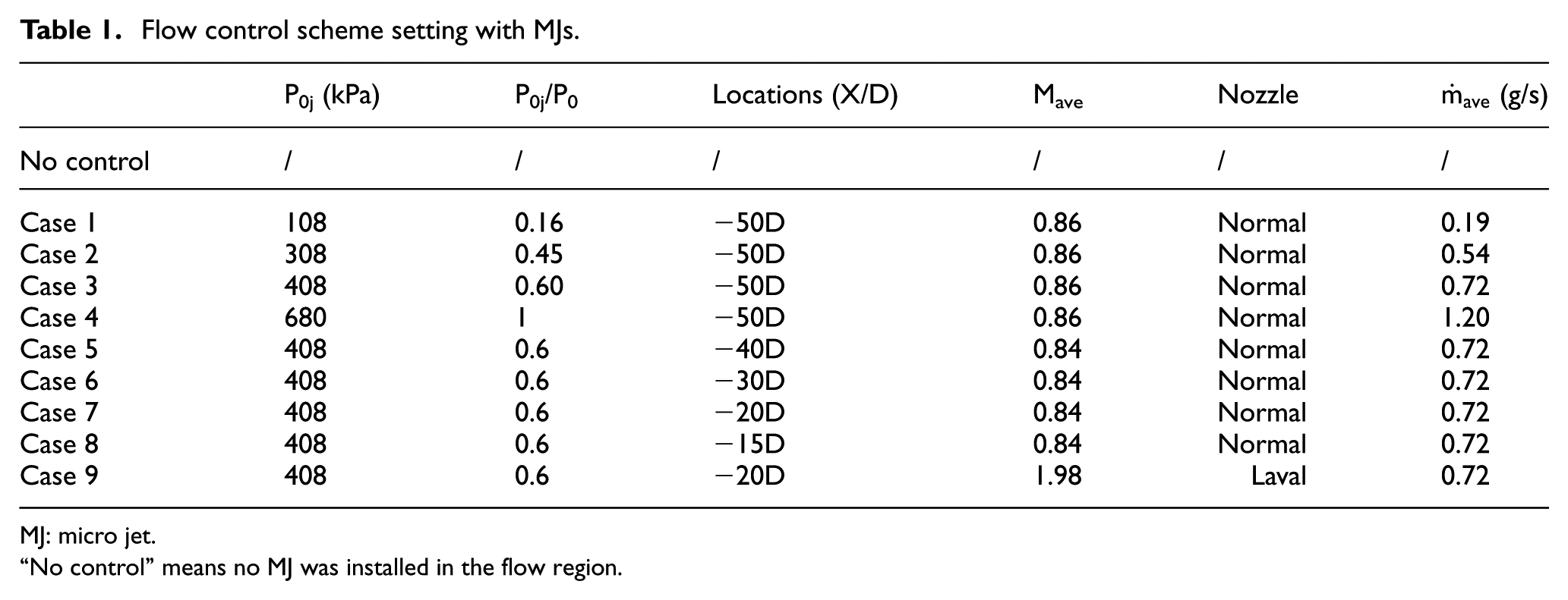
MJ: micro jet.
“No control” means no MJ was installed in the flow region.
The ANSYS/Fluent 16.1 has been used to solve the Reynolds-averaged Navier–Stokes (RANS) equations. The turbulent flow was simulated by k–ε turbulence model coupled with enhanced wall treatment wall function. The distance between the first layer node and the wall was set to be 0.001 mm to ensure y+≈1 for accurately solving the viscous sublayer. The multigrid initialization technology was used to accelerate the calculations. All cases adopt the same layout of structured grid, as shown in Figure 4.

Grid scheme.
Validations
Matthew et al. 21 have carried out a detailed experimental research in the flow field of compression corner. The experimental model is the same as that used in this article and is relatively representative. To eliminate the influence of grid number, grid schemes with number of 0.6 × 10⁶, 1.0 × 10⁶, and 1.6 × 10⁶ were used. The wall pressure and the boundary layer flow velocity distributions are shown in Figure 5 (δ is the boundary layer thickness, P∞ is the flow static pressure, U∞ is the flow velocity). The figure shows that the grid schemes with number of 1.0 × 10⁶ and 1.6 × 10⁶ have a similar trend about the calculation results. This verifies the reliability of the calculation method. To cut down the computing costs, grids with a total number of 1.0 × 10⁶ are selected in this article.
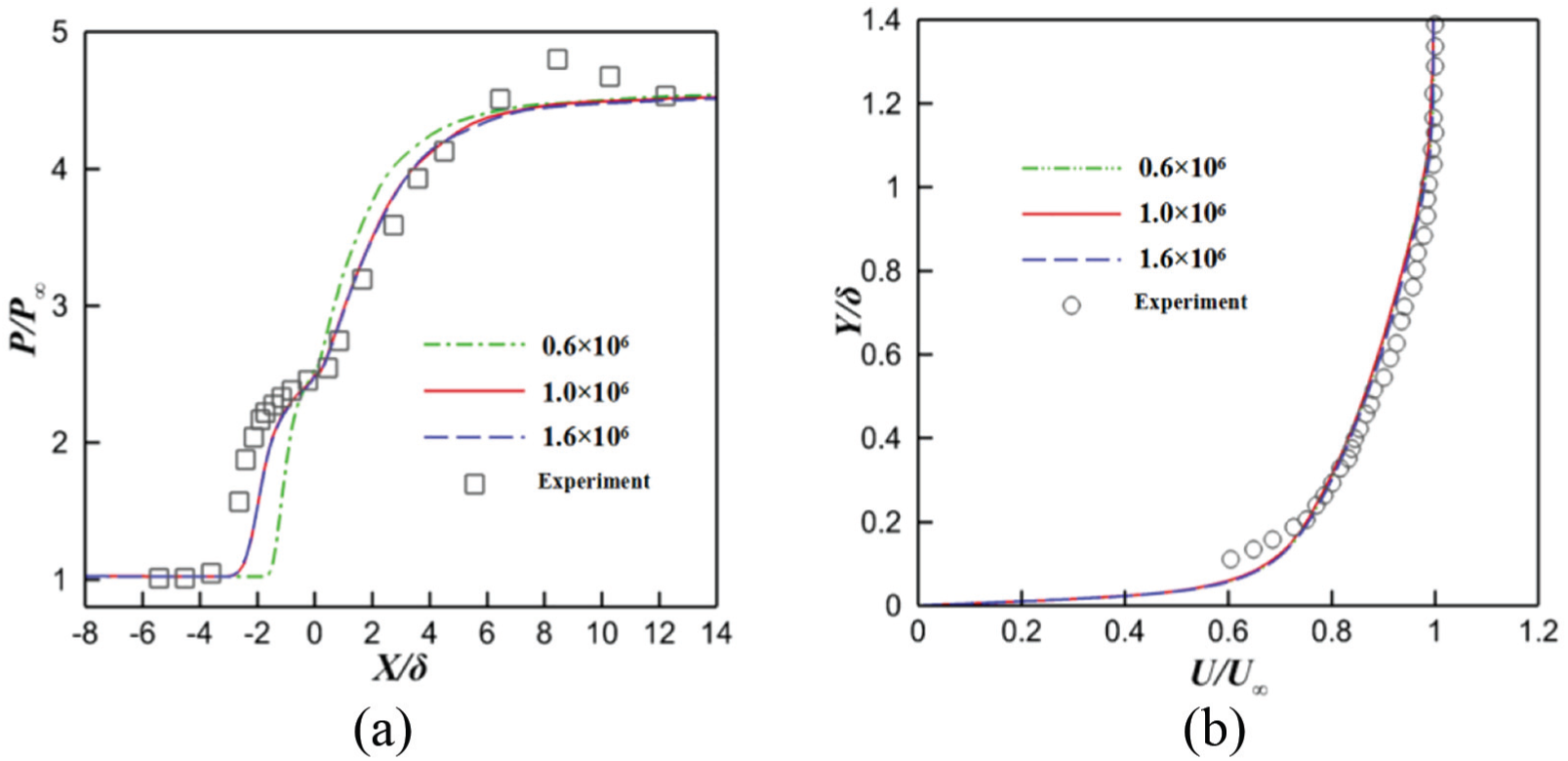
Comparison of simulation and experiment results: (a) comparison of static pressure distributions and (b) comparison of streamwise velocity distributions.
Results and discussion
The interaction between MJ and supersonic mainstream results in a complicated flow structure in the orifice, which affects the downstream boundary layer flow and the characteristics of SWBLI. This article focuses on the flow control mechanism of MJs in supersonic compression corner flow field.
Flow characteristics around MJ
Figure 6 shows the Mach number contours and streamlines with different MJ designs on spanwise plane. The complicated flow structure is formed at the MJ outlet. (1) Bow shock wave occurs due to the obstruction effect from MJ. The resulting bow shock wave leads to larger adverse pressure gradient, causing flow separation I in the upstream area of MJ. The flow velocity decreases across the shock wave, which reduces the shock wave strength downstream. (2) The jet flow expands to the outlet and ends up at the barrel shock wave and Mach disk. (3) It forms an obvious flow boundary between jet flow and mainstream. (4) The barrel shock wave leads to the downstream flow separation II.

Mach number contours and streamlines with different MJ designs: (a) Case 1, (b) Case 2, (c) Case 3, (d) Case 4, (e) Case 5, (f) Case 6, (g) Case 7, (h) Case 8, and (i) Case 9.
The vortex structures around typical MJs are shown in Figure 7; they are mainly composed of three pairs of vortex: the horseshoe vortex pair which is formed by the jet flow obstruction effect near the wall; the counter-rotating vortex pair (CVP), a rotational vortex pair which is formed by mixing shearing between the jet flow and mainstream; and the secondary vortex pair, which is formed by shearing stress between CVP and the wall. CVP is the main factor in influencing the SWBLI characteristics due to its larger vortex intensity and wider function range.

The vortex structures around MJs: (a) Case 7 and (b) Case 9.
Different injection pressures
Various MJ injection pressure ratios lead to different jet outlet flow expansions. It has different effects on downstream flow and SWBLI. As shown in Figure 6(a)–(d), with an increase in injection pressure ratio, jet outlet flow expansion and the resulting bow shock wave strength and flow separations have been enhanced. As shown in Figure 6(d), Case 4, which responds to the higher injection pressure ratio, the strongest expansion, and the obstruction effect on the mainstream, leads to a larger distance from interaction boundary to wall relative to other cases, thus resulting in a larger function range on the mainstream. At the same time, Figure 6(a)–(d) validates that the increase in injection pressure ratio also aggravates separation II.
It can be concluded that MJ injection with higher pressure ratio leads to stronger obstruction effect, jet expansion, and flow separations.
Different injection positions
As shown in Figure 6(c), (e)–(h), because the jet inlet total pressure in each case is the same, the overall flow situation around the MJ is similar. The pressure downstream of the MJ is relatively low and increases gradually in the streamwise direction. In Case 8, low Mach number area extends to the edge of downstream due to the relatively smaller distance from MJ to compression corner. As a result, separation II is connected to the corner separation area, as shown in Figure 6(h). In addition, the smaller distance leads to the combination of bow shock wave and the corner shock wave, decelerating the downstream flow velocity and resulting in low Mach number area.
Different injection nozzle geometries
MJ with the same injection pressure ratios and locations but different nozzle types will inevitably produce a different velocity and expansion at the outlet, thus forming a different flow structure at the orifice (shown in Figure 7). It also influences the downstream SWBLI and produces a different controlling effect. This article studies MJ controlling effect on SWBLI at compression corner by comparing two types of MJs, that is, one with the convergent nozzle (Case 7) and the other with the Laval nozzle. Study shows that the Laval nozzle outlet produces higher flow velocity, lower outlet pressure, and weaker under-expansion compared with the convergent nozzle. As for the Laval nozzle, high velocity at the gas outlet leads to a larger normal extent when it interacts with the mainstream and a larger distance from the jet boundary to the wall.
In addition, at the location X/D = −15, the CVP vorticity in Case 9 (23.2 × 10⁴) is slightly smaller than that in Case 7 (28.4 × 10⁴). This is mainly because the degree of expansion is weaker in Case 9. CVP is produced by the shear mixing between the outlet expansion jet flows and the mainstream. In the same inflow condition, more expanded jet flow leads to stronger CVP. In addition, the MJ shows larger effective range in Case 9, and it is considered that the controlling effect in Case 9 is better than that in Case 7.
Flow characteristics downstream of the MJs
Figure 8 shows the distributions of vorticity and streamline at different streamwise locations when the CVP moves downstream. During the evolution process of the CVP, the vorticity decreases and the vortex core positions appear to be of three-dimensional characteristics: both of the relative distance from the vortex cores to the wall surface and the vortex core spacing increased along the streamwise direction.

Vorticity contours and streamlines of CVP downstream of MJs (Case 3).
Different injection pressures
Figure 9 shows the developing trends of CPV in the streamwise direction. The maximum vorticity, the distance between vortex core and wall, and the vortex core spacing are quantitatively analyzed. As shown in Figure 9(a), CVPs in Cases 2 and 3 have larger vorticity value, while Case 1 has the minimum vorticity. It shows that higher injection pressure ratio is beneficial for producing CVP, but it does not mean that the higher the better. Thus, there exists an optimal injection pressure ratio. In all cases, the CVP movement leads to vorticity dissipation, and the outlet vorticity around the MJ orifice is the most significant factor. In Cases 1–4, compared with that at X/D =−40, the vorticity dissipations at X/D =−25 are, respectively, 78%, 75%, 73%, and 72%, which proves that streamwise CVP dissipates slower when MJ has higher injection pressure.

Characteristics of CVPs: (a) maximum vorticity versus streamwise distance, (b) distance between the vortex cores to the wall versus streamwise distance, and (c) vortex pair spacing versus streamwise distance.
In addition, Figure 9(b) shows the location changes of CVP vortex cores along the Y direction. The CVP is dissipated along the streamwise direction and it goes away from the wall gradually, which leads to a wilder controlling scope. The MJ introduces fluid with higher energy close to the wall, and it can be beneficial to activate the low-energy fluid at the bottom of the boundary layer. As shown in the picture, the CVP cores have the largest distance from the wall in Case 4, while minimum spacing for Case 2 and Case 1.
Figure 9(c) shows the changes of the vortex core spacing. The gap becomes larger because of the dissipation of CVP downstream. For the high pressure ratio case, CVP is so strong that a larger gap is created between vortex cores and a wider function range. The same conclusion can be obtained in Figure 10. The spanwise wall shear coefficient becomes larger with the increase in pressure ratio injection. (In this figure,

Distributions of wall shear coefficients at location X/D = −35.
Figure 11 shows the flow velocity in different locations at Z/D = −1 near the wall boundary layer. The distributions of streamwise velocity become full within the boundary layer when the MJ is used, and this trend is becoming more obvious with increasing injection pressure ratio. A similar situation occurs with the streamwise MJ position moving closer to the corner separation. The status of the boundary layer is mainly associated with the CVP strength, disturbance range, and the degree of dissipation. The cases with higher injection pressure ratios show an advantage (such as Case 3 and Case 4) in controlling effect. It should be noted that Figure 11 shows the enlarged graph of velocity distribution between U = 0.4U∞ and U = 0.5U∞. And horizontal x-axis (U/U∞) represents the ratio of flow velocity near the wall boundary layer to the far-field velocity, while vertical y-axis (Y/D) stands for the ratio of the vertical distance on the wall to the nozzle outlet diameter.

The distributions of streamwise boundary layer velocity at different locations. (a) X/D = −35, (b) X/D = −30, and (c) X/D = −25.
Different injection positions
Figure 12 shows the contour of vorticity at different downstream cutting planes. Due to the same injection pressure ratio, Cases 5–8 have a similar CVP intensity, as shown in Figure 13(a). But in each case, CVPs show different distances relative to the corner and various degrees of dissipation downstream. CVP produced by MJ near the corner separation zone alleviates SWBLI with weaker attenuation; thus, it has better controlling effect, which is shown in Figure 12(c). However, it does not mean that the closer distance between MJ and the corner guarantees better controlling effect. When the location of MJ is too close to the corner, the controlling effect of CVP on SWBLI is not good. This is because both the CVP strength and height do not have enough time to fully develop. As shown in Figure 13(a), the controlling effect is not in perfect status for Case 8 because of the short distance between CVP and the wall. Also, CVP is sensitive to the influence induced from the corner separation zone and the shock wave. In Figure 13(a), Case 3 and Cases 5–7 have similar CVP situation. However, the Mach number downstream of MJ in Case 8 is lower than that in other cases, resulting in weaker CVP vorticity—approximately 87% in other cases. It can be concluded that the controlling effect would not be good enough when MJ is too close to the corner. Case 7 gives the best controlling effect at the location X/D = −20.

The contours of vorticity at different downstream cutting planes: (a) Case 5, (b) Case 6, (c) Case 7, and (d) Case 8.

Characteristics of CVPs: (a) maximum vorticity versus streamwise locations and (b) distance between vortex spacing versus wall surface.
The downstream flow is also improved with the applications of MJ. Figure 14 shows the distributions of streamwise velocity at location Z/D =−1 andX/D =−10. It shows that there exists low-energy fluid near the wall in no-control case. There is an improvement in boundary layers and the velocity distributions become full when applying MJs. Cases 6 and 7 show robust boundary layers, while Cases 3 and 5 show poor status.

Distributions of streamwise velocity at location(Z/D = −1 and X/D = −10).
Different injection nozzle types
Figure 15 shows the vorticity contours with various schemes at locations X/D = −15, X/D = −13, and X/D = −10. The convergent nozzle in Case 7 and the Laval divergent nozzle in Case 9 show similar vorticity distributions, vortex core positions, and effective ranges. As for Case 9, the vorticity is more concentrated and the vortex spacing is bigger. Thus, the CVP is dissipated more slowly and shows wider controlling range in normal direction.
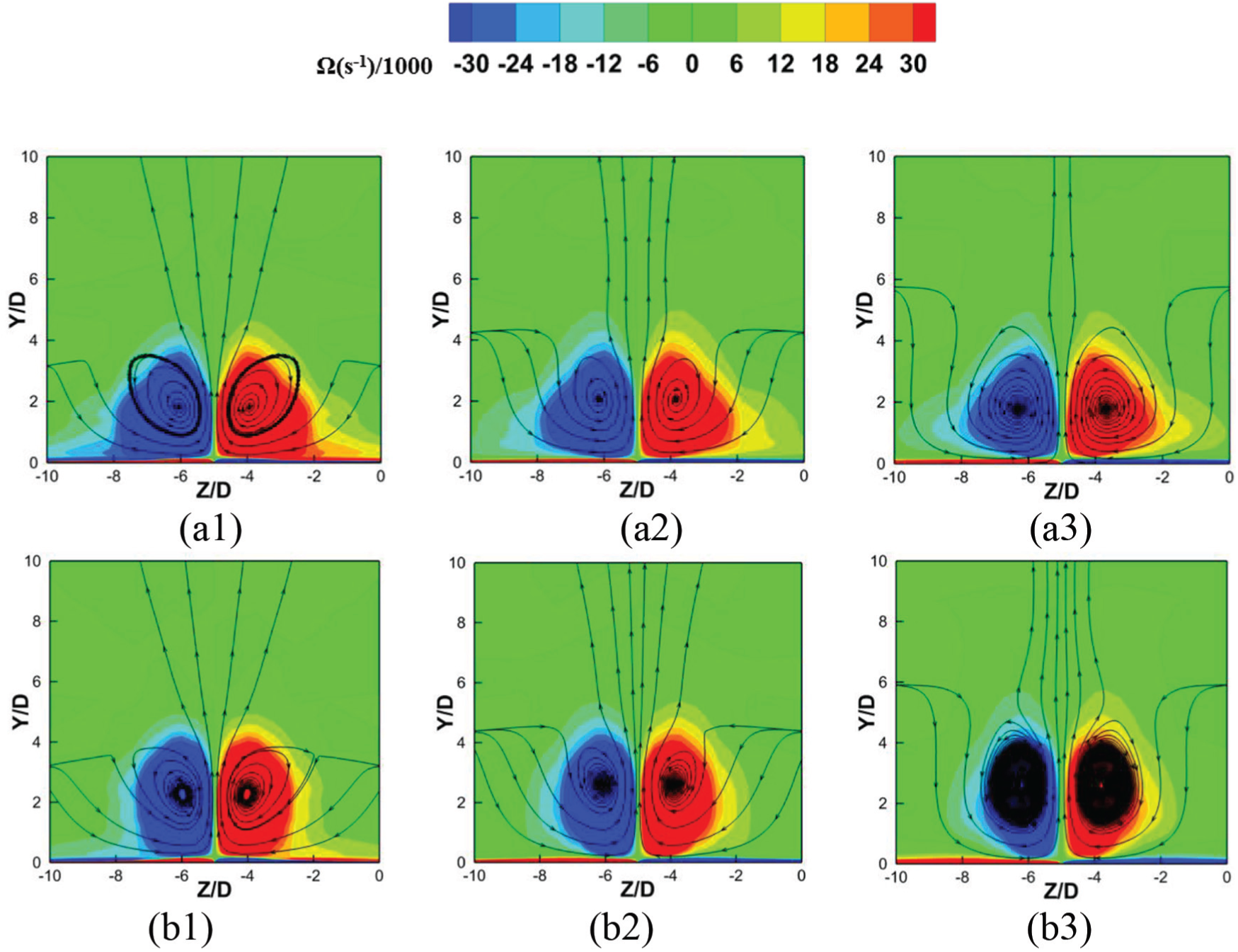
Contours of vorticity at various locations: (a1) Case 7, X/D = −15; (a2) Case 1, X/D = −13; (a3) Case 1, X/D = −10; (b1) Case 9, X/D = −15; (b2) Case 4, X/D = −13; (b3) Case 4, X/D = −10.
Figure 13(a) shows that the CVPs in both the convergent nozzle and the Laval divergent nozzle show an attenuating trend. Even though CVP strength is bigger in Case 7, the CVP in Case 9 shows smaller extent of attenuation. Thus, there is no difference in vorticity intensity at location X/D = −10. Due to the vortex core distance relative to wall surface in Case 9 being greater than that in Case 7(as shown in Figure 13(b)), more high-energy fluid can be introduced to the region near wall.
Flow characteristics around ramp and MJ flow control mechanisms
The CVPs show an obvious effect on SWBLI characteristics when it reached the SWBLI area near the corner. The MJ controlling effects on SWBLI characteristics with different injection pressure ratios, positions, and nozzle types are shown below.
Different injection pressures
Figure 16 shows the contour of wall shear coefficients along the Y direction. To identify separation area, the contours ignore the parts larger than 0. Figure 16(a) shows the separation and reattachment positions without MJ. Relative to the no-control case, the separation area in other cases becomes smaller with the applications of MJ, especially in Figure 16(d), in which close to 70% separation area is eliminated. As mentioned above, increasing the injection pressure ratio is beneficial for removing the low-energy fluid at the bottom of boundary layer. It improves the ability of resisting adverse pressure gradient flow separations, reflecting good controlling effect in spanwise direction, as shown in Figure 16(d) and (e).

The contours of wall shearing coefficients: (a) no control, (b) Case 1, (c) Case 2, (d) Case 3, (e) Case 4, (f) Case 5,(g) Case 6, (h) Case 7, (i) Case 8, and (j) Case 9.
Figure 17 shows the pressure coefficient contours—

The pressure coefficient contours on the middle span plane. (a) no control, (b) Case 1, (c) Case 2, (d) Case 3,(e) Case 4, (f) Case 5, (g) Case 6, (h) Case 7, (i) Case 8, and (j) Case 9.
Different injection positions
Compared with the no-control case, the flow separation is reduced significantly in Figure 16(f)–(i) with MJs. The cases close to the corner (Cases 7 and 8) show better controlling effects that stronger adverse pressure can be resisted and nearly 90% flow separations can be eliminated. It should be mentioned that the MJ is too close to the corner in Case 8 that the MJ flow separations and corner separations are connected, resulting in poor controlling effect.
In the comparison of Figure 17 (d)–(i), the smaller separation area leads to reduced λ area, decreasing distance between shock wave intersection and wall. The distance was decreased by about 40% in both Cases 6 and 7. In addition, due to the MJ being too close to the corner in Case 8, the bow shock waves and λ shock waves are combined together. Totally, the corner separations have been eliminated significantly with applications of MJs.
Different injection nozzle types
In the comparison of Figure 16(h) and (j), it can be found that with the effects of MJ, the distance between the separation position and the reattachment position is sharply reduced. In Case 9, the Laval divergent nozzles case shows the best performance. Compared with the convergent nozzle, CVPs in Case 9 mainly concentrate on the spanwise locations and the distance between vortex core and the wall is longer. Thus, MJ shows poor controlling effect on both sides of the flow region near the corner with some flow separations remaining. However, this disadvantage can be compensated by adjusting the spanwise arrays of MJs, that is, reducing the layout spacing, so that MJ can be set closer to eliminate the spanwise separations.
The similar controlling effects are shown in the comparison of Figure 17(h) and (j). The distance between the shock intersection and the wall is decreased significantly when compared with the no-control case. The distance is cut down by nearly 50% in Case 9. This change is due to MJ causing a shorter distance between the separation position and the reattachment position. The separation shock wave moves downstream, and the reattachment shock wave moves upstream, resulting in the distance between the shock intersection and the wall being reduced. In addition, the change of shock waves is shown in the distributions of streamlines in Figure 17(h) and (j). Figure 17(h) shows severer separations in the corner, and the corner separation zone is effectively reduced with using MJs, with an obvious improvement in the characteristics of SWBLI.
Conclusion
Compression corner is a typical outside structure of the aircraft, near which the supersonic flow leads to obvious SWBLI phenomenon and forms serious flow separations, thus influencing the aircraft performance. MJ technology has a broad application prospect in supersonic flow control field. This article focuses on the flow structures around MJ and the SWBLI characteristics between the MJ and the corner from three aspects: the MJ flow injection pressure, the MJ flow position, and the nozzle types to explore the controlling mechanisms. The main conclusions are as follows:
The interaction between MJ and supersonic flow forms complex flow structures, including bow shock, barrel shock, Mach disk, the horseshoe vortex flow, CVP, and so on. The MJ blockage effect on incoming flow can reduce the downstream velocity and weaken the shock wave intensity. Thus, almost all MJ schemes show better performance than the uncontrolled designs. MJ controlling mechanisms mainly depend on three aspects. The first one is the production of CVPs. CVP is the main factor to realize the aim of flow control. The downwash effect of CVP can bring the high-energy fluid in the boundary layer near the wall, activate the low-energy fluid, enhance the capacity of anti-inverse pressure, and eliminate the flow separations. The second aspect is that the bow shocks upstream of the MJ obviously reduce the flow velocity, weakening the shock wave strength around the corner and improving the characters of SWBLI. And the third aspect is the actuating range of MJ, that is, the distance between the wall and CVPs. If the distance is closer, the normal effective range is smaller. When the distance is larger, the flow characteristic around the corner can be improved in a wider range.
Different injection pressures show different controlling effects on the supersonic compression corner. Compared with low MJ injection pressure, higher MJ injection pressure produces stronger CVPs and longer distance between vortex cores and wall. Taking the controlling effect and injection energy into account, the MJ provided the optimal controlling effect when the injection pressure ratio is set to be 0.6. Compared with the case without control, the corner separation zone is reduced by nearly 70%. In addition, the distance between shock wave intersection and the wall has been decreased by nearly 37%, with separation shock wave intensity weakened by nearly 12%.
Different flow positions also have different controlling effect on the supersonic compression corner flows. When the injection pressures are the same, the CVP intensity is almost the same in different position cases. The CVP dissipates during its development process toward downstream. Thus, the MJ closer to the corner leads to stronger flow controlling effect. However, the shorter distance results in a smaller effective scale and there exist a trade-off. Comparing all of the cases comprehensively, Case 7 shows the best controlling effect with MJ located near the separation zone. In this case, the flow separation area is cut down by nearly 90%, the distance between the shock wave and the wall is reduced by about 40%, and the separation shock wave intensity is weakened by almost 14%. Case 8 in which MJ locates within the corner separation zone shows poor controlling effect.
Assuming that injection ratio and position remain unchanged, MJ with Laval divergent nozzle leads to more concentrated CVPs due to higher exit velocity. Longer distance between the vortex core position and the wall introduces fluid with higher energy into the boundary layer to activate the low-energy fluid and enhance stronger resistant ability, thus resulting in better controlling effect on the separation flows at the corner. The length of separation zone is cut by nearly 70%, the distance between shock intersection and the wall is reduced by up to 50%, and the separation shock wave intensity is weakened by about 15%.
Footnotes
Handling Editor: Pietro Scandura
Declaration of conflicting interests
The author(s) declared no potential conflicts of interest with respect to the research, authorship, and/or publication of this article.
Funding
The author(s) disclosed receipt of the following financial support for the research, authorship, and/or publication of this article: This research has benefited greatly from the generous support of the National Natural Science Foundation of China (Grant No. 51436002) and the State Key Laboratory of Explosion Science and Technology (ZDKT17-01).