
Abstract
Energy generation technologies that use piezoelectric materials as uninterrupted power supplies are one of the most practical solutions of low-power wireless sensor network. The piezoelectric generator collects mechanical energy from the environment and transforms it into electricity to supply to microelectronic devices. Thus, these alternative energy sources can reduce the consumption of batteries, thereby reducing environmental pollution. Piezoelectric materials can work in the bending, compression, and shear modes, which are named as d31, d33, and d15 modes, respectively. In this study, a piezo stack which worked in d31 mode has been designed and integrated into an energy harvesting pedal. A novel compliant amplifying mechanism has to be designed to amplify the input load so that the high-stiffness piezoelectric stack can achieve a large energy output at a lower input force. This compliant mechanism has been designed by the pseudo-rigid-body and topology optimization methods. The amplification ratios of different sized flexible amplification mechanisms are calculated through the finite element analysis and validated by experiments. Finally, a pedal generator has been made and the test results show that the collected electricity can effectively drive a low-power microcontroller, sensor, and other devices of these kinds.
Introduction
Energy harvesting technologies that can collect energy from the surroundings (e.g. solar power, thermal energy, wind energy, mechanical energy, and so on) and store it for small autonomous devices have been making rapid progress recently. In terms of energy collection, mechanical energy is more durable and less easily affected by uncertain factors (e.g. weather). There are three types of transducers that can convert mechanical energy into electrical energy: electromagnetic type, electrostatic type, and piezoelectric type.1–7 The piezoelectric transducer has the advantages of simple structure, easy miniaturization, superior energy density, and no-bias voltage requirement, and has broad prospects in the energy harvesting applications. Thus, piezoelectric materials are proposed for use in energy harvesting devices. Each piezoelectric material can operate as an energy generator in three types of coupling modes, which are named as d31, d33, and d15 modes. 8 As showed in Figure 1(a), the most commonly used piezoelectric harvester is the d31 mode in which normal strain is perpendicular to the direction of the electric field. Under such a condition, the piezoelectric material can work in pure bending mode with a low load. Figure 1(b) provides a graphic representation of the d33 mode in which normal strain is parallel to the direction of the electric field. It can be applied to the situation in which the piezoelectric material should bear a high compressive load as an energy generator. Figure 1(c) shows the d15 mode in which shear strain is perpendicular to the direction of the electric field. This mode is rarely used in energy generator because the pure shear deformation is hard to realize in practice.
Illustration of (a) the d31 mode, (b) the d33 mode, and (c) the d15 mode for piezoelectric materials.
According to the ambient excitation, the piezoelectric energy generator can be divided into two types: free excitation mode and forced excitation mode. In the free excitation mode, rigid block is attached to the piezoelectric vibrator to constitute the spring damping system. When external excitation acts on the base of the vibrator, the piezoelectric vibrator resonates and then generates electrical energy. The piezoelectric vibrator is usually fixed on the base in the form of a cantilever beam. Due to the natural frequency limitation of the spring damping system, the size of the cantilever beam needs to be reasonably designed, so that the environmental excitation can be as close as possible to the natural frequency of the cantilever beam. The forced excitation mode means that the external excitation directly acts on the piezoelectric vibrator. In order to reduce the structural complexity and save material cost, the piezoelectric material working under this mode is usually made into a thicker size, and therefore has a large stiffness in the direction of vibration relative to resonant mode. To some extent, mechanical amplifying mechanism needs to be designed to amplify the input load so that the high-stiffness piezoelectric vibrator can achieve a large energy output at a lower input force.
The compliant mechanism is a device that can deform in a prearranged manner and accomplish specific tasks. It has several advantages compared with a rigid mechanism and can be fabricated in a simplified way, since it consists of fewer parts and needs less assembly work. Besides, this compactly structured mechanism can reduce and even avoid the connection of kinematic joints, thus reducing abrasion and clearance, and avoiding lubrication. 9 There are mainly two ways to design the compliant mechanism: the pseudo-rigid-body (PRB) method and the topology optimization method. 10 The PRB model is a set of diagrams and formulas, which describes the corresponding relationship between the movement and strength of elastic elements and rigid structures. This model is more useful in solving the component-level design issues, since it characterizes the whole compliant element. The other way to design the compliant mechanism is the topology optimization method.11,12 Compared with the PRB method, it always provides novel ideas for solving the design problems of the compliant mechanism, since it always searches for the best topology in the flexible structure. However, in most cases, semi-empirical PRB method can provide a more compact structure design.
The solid isotropic material with penalization (SIMP) topology optimization method is used as the most important method to optimize the structure. This method is the most commonly used one of all the topology optimization methods, which is proposed by BendsØe and Sigmund. This method takes the relative density of each element as the design variable.13–19 To avoid intermediate densities, it employs the penalty factor method when calculating unit stiffness. Furthermore, to effectively overcome the checkerboard phenomenon, the filtering method is adopted.17,18 Using the MATLAB software, Sigmund wrote a code of 99 lines, which successfully applied the SIMP method to solve a typical structural optimization issue. 20 It holds size as a constraint and makes the structural compliance minimization its objective function. With the development of the design of structural optimization, some commercial software gradually appeared. OptiStruct, a software developed by Altair, is used in this study to develop the structural optimization design. This software can solve problems commonly faced in the topology optimization of linear finite element models (such as compliance, modality, and frequency response). It can also effectively avoid the checkerboard phenomenon due to its built-in filter technique. Besides, it supports a range of practical engineering constraints of topology optimization (such as the constraints of extension, pattern, symmetry, and a minimum size). It is more convenient for users to apply the results in their engineering practices.
In this study, a piezoelectric stack has been developed and integrated into a pedal and the piezoelectric material is PZT4. Furthermore, a novel compliant load amplifier has been designed by the PRB method and the topology optimization method to make sure the piezo stacks have greater energy output under low load. The reasonable compliant mechanism size has been chosen according to the piezo stacks’ stiffness to achieve better magnification ratio. Finally, a pedal demo has been taken and the test results show the maximum value of peak power is 230 µW at a resistance of 110 kΩ in parallel stack mode and 427 µW at a resistance of 800 kΩ in series stack mode when the exciting load increases at 15 N and frequency is 1 Hz.
Pedal design
The design of the piezoelectric energy generator pedal includes the following parts: the piezoelectric stack module composed of the drum-type unit for piezoelectric power generation; the load amplifier module using the compliant mechanism; and the support and transfer parts, which transfers the amplifier output to the piezoelectric stack. The following sections will introduce these modules.
Piezoelectric stacks design
The design of the piezoelectric stack is shown in Figure 2(b). As the basic power-generating unit of piezoelectric stack, the piezoelectric vibrator has two available structures: the beam-type and the disk-type. Compared with the beam-type piezoelectric vibrator, the other has the advantages of high intensity and easy-linked structure. Thus, this article uses the disk-type piezoelectric vibrator as the basic power-generating unit of piezoelectric stack. As shown in Figure 2(a), the disk-type piezoelectric unit is the basic unit of piezoelectric stack, which consists of two circular piezoelectric vibrators and a connector for connection and support. Two circular piezoelectric vibrators are embedded in the grooves on both sides of the connector for connection and support, bonding and fixing with the alpha-cyanoacrylate glue and forming a cavum in the middle part. The circular piezoelectric vibrator is made of a circular piezoelectric PZT4 piece affixed to a brass plate though alpha-cyanoacrylate glue. The remaining parts are made of 3D printing, and the material is polycarbonate-ABS (PC-ABS). The size parameters of the disk-type piezoelectric vibrator are shown in Table 1. Assuming that the bonded surface is completely rigid, the static axial stiffness of drum-unit and circular vibrator could be calculated by the finite element method using ANSYS as shown in Table 1. The mechanical properties of the materials used in the analysis are shown in Table 2 and formula (1).
(a) A single drum piezoelectric piece, (b) piezoelectric stack, and (c) drum-unit stiffness FEA analysis.
Size and stiffness parameters of the disk-type piezoelectric vibrator.

Mechanical properties of materials in analysis.

PC-ABS: polycarbonate-ABS.
The table shows that under the same input force, the deformation of a drum-type piezoelectric unit is almost two times bigger than a single circular piezoelectric vibrator. As shown in Figure 2(b), n drum-type piezoelectric units are connected through connection blocks and form a multiunit series piezoelectric stack. Theoretically, under the same concentrated load, the deformation of a multi-unit series piezoelectric stack is close to 2n times than a single circular piezoelectric vibrator

Load amplifier design
The load amplifier would be applied to amplify the input load of the rider to ensure enough power output is available even in a low input load situation. To avoid the complex assembly work and motion errors of the rigid mechanism, it would be a good choice to employ the compliant mechanism as a mechanical amplifier. The compliant mechanism can be divided in to two groups: the lumped compliant mechanism and the distributed compliant mechanism. In this article, the former one is adapted. First, we should make a PRB model of the mechanism in accordance with the requirements. There are commonly three kinds of lumped compliant hinges with a plane symmetric notch, including hinges with circular openings, hinges with the oval notch, and hinges with the beam-type notch. Compared with beam-type notch hinges, circular opening hinges have greater stiffness and high kinematics accuracy. Compared with the oval notch hinge, parametric design can be realized with fewer design variables in the case of meeting the requirements of strength and accuracy. Thus, circular opening hinges are used in this article (Figure 3).

(a) Size parameters of the complaint joint, (b) rotation stiffness FEA analysis, and (c) tension-compression stiffness FEA analysis.
Table 3 showed the influence of the minimum thickness parameter T of the flexible hinge on the linear stiffness and the rotational stiffness under the condition that other parameters are unchanged. Rotation and tension-compression stiffness of compliant joint could be calculated by the finite element method using ANSYS. The mechanical properties of the materials used in the analysis are shown in Table 2. The compliance matrix of the piezo material is shown as formula (1).
The size parameters and rotation stiffness of the complaint joint.

In order to simplify the model, we make a model on the assumption that the coordinate of the hinge’s symmetry center keeps unchanged. Using the PRB method, the compliant mechanism could be replaced by a series of rigid rods and revolute pairs (Figure 4). The torsional spring stiffness is used to describe the torsional stiffness of a flexible hinge. A line constraint can be used instead of the contact joint. Using the virtual work principle, the equilibrium equations could be developed and solved. The load amplification factor with different joint, which is shown in the Table 3, could be calculated.

PRB model of the compliant mechanism amplifier.
To allow the material of the load amplifier to be grossly underused, a design area that is based on the above computing result is set up, and the topology optimization of the compliant mechanism is performed for the design area. The definition of the design area is shown in the figure. Therefore, it is assumed that the load that existed in the input and output points of the lever is equal and opposite assuming that the piezo stack only has the degrees of freedom along the copper electrode normal direction, and the stiffness is linear in this direction. Considering that the weight of the piezoelectric stack is light, and the working displacement and operating frequency are low, the acceleration and velocity of its center of gravity are low, thus the inertial force and damping force due to the equivalent mass during the forced vibration process are much smaller than the exciting force. Thus, the piezo stack can be replaced by a linear spring with equal stiffness. In addition, to facilitate the optimization and analysis, a linear spring with the same stiffness as that of the contact stiffness is used at the contact point. The structure is discretized by the two-order hexahedral element of 20 nodes, and its topological optimization is realized by using the SIMP method. 10 The description of the whole optimization problem is shown in the following formula. The design part means the part that does not include the flexible hinges, and the objective function is to minimize the compliance of the design part. The volume rate constraint is 0.5 and the material used is PC-ABS
where U is global displacement, F are force vectors, K is the global stiffness matrix,

(a) Design space and boundary conditions and (b) topology result.
Pedal design and analysis
Finally, the piezoelectric stack and load compliant amplifier could be integrated into a pedal, as shown in Figure 6, and the internal structure of the pedal is showed in Figure 7. The subsequent finite element analysis would be carried out. 11 The mechanical properties of the materials used in the analysis are shown in Table 2.
(a) Final design of the pedal and (b) section view of the pedal.
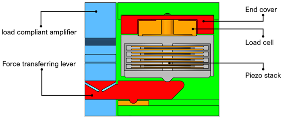
Internal structure of the pedal.
The finite element model and von Mises stress distribution of the pedal, when the input force is 15 N, is shown in Figure 8. The maximum value stress of the aluminum alloy is 104.25 MPa and the maximum value stress of the PC-ABS material is 30.4 MPa, which, under the allowable stresses, is summarized in Table 2.

Von Mises stress distribution of the pedal.
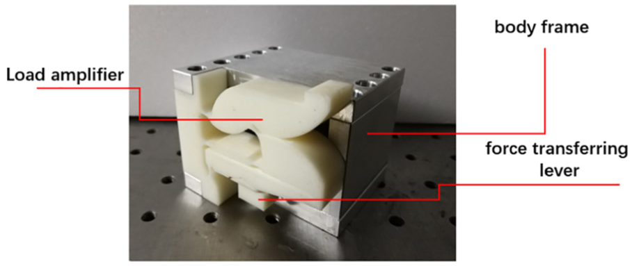
Load amplifier on the pedal.
Experiment
Fabrication of the pedal
The piezoelectric material used in this article is PZT4 piezoelectric ceramic material, and its material parameters are shown in Table 1. The piezoelectric vibrator consists of the piezoelectric-piece and brass electrodes, which are fixed by the alpha-cyanoacrylate glue, and its size parameters are shown in Table 1. A drum-type piezoelectric unit is composed of piezoelectric vibrators through a connector, which are fixed with a strong adhesive. The varnished wire of 0.3 mm in diameter is welded on the positive and negative poles of the piezoelectric vibrator with the help of the electric soldering iron, and it is extracted from the small hole on the side of the connector.
Experiment procedure
In this experiment, a reciprocating vertical loading device is designed, which is mainly composed of Dynamixel MX-106 high precision servo motor, gear group, guideline slide table, load cell, and pin. The servo motor leads the gear group to drive the slide table in order to achieve the reciprocating motion of the pin. The data signal of load cell 1 is read through the NI-9237 data acquisition module and transferred to the computer. The load control program written by the LabVIEW 12 based on the proportional integral (PI) controller is designed to control the load force in real time and realize the loading of the 15 N under 1 Hz. At the same time, the force in the piezoelectric stack can be measured in real time by the load cell 2 which is in series connection with pedal piezoelectric stack, and the relationship between the input and output loads can be obtained. The energy output of piezoelectric stack is processed by standard energy collection circuit and is confirmed by oscilloscope.
The loading experiment is performed on four kinds of compliant load amplifiers, with different thickness joint through the above test system, and the amplification effect of the input load is also tested. Further, the experiment tests the power output characteristics of the parallel piezo stack, which varies with the load under the influence of the load amplifier. The test frequency is 1 Hz and the input load is 15 N. The resistance changes from
Results and discussion
The following conclusions can be made through the analysis conducted in this study. The finite element calculations of the piezoelectric stack stiffness are close to the actual test results in Table 4. However, there are still some errors. The possible causes of these errors can be divided into two groups: analysis errors and experimental errors. The former ones are mainly error about the given value and the actual value of the material mechanical properties. In addition, the later ones are caused by adhesive shedding, assembly errors, and some other aspects. The comparison of open-circuit voltage of the generator with or without amplifier in series and parallel connection modes is shown in Figure 10 when thickness is 0.5 mm.
Load amplification factor using different modeling methods.
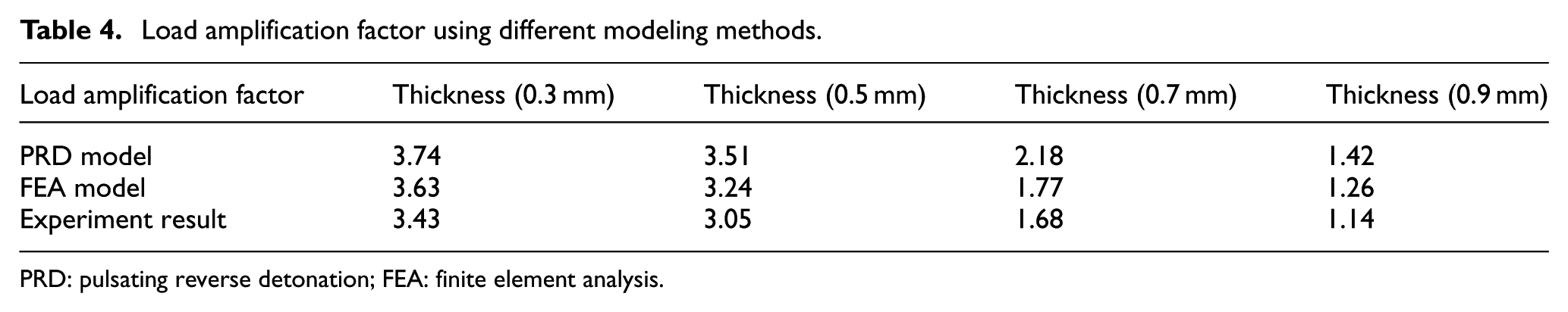
PRD: pulsating reverse detonation; FEA: finite element analysis.

Piezoelectric pedal test system.
The force magnification of the PRB model in Section 2 is strongly affected by the torsional stiffness of the flexible hinge and the loading stiffness. With the decrease of the torsional stiffness, the magnification increases. However, the torsional stiffness cannot be reduced indefinitely. Magnification also has a certain relationship with the load stiffness. Compared with the finite element model, the magnification of PRB model is larger than that of the finite element model under the same condition. There are two reasons for this result. First, the PRB model rigidly simplified all the parts except the flexible hinge. However, the deformation of these parts cannot be ignored if an accurate analysis is needed. Second, the nonlinear behavior of the flexible mechanism will change the overall configuration of the system to a certain extent, thus affecting the system’s input and output characteristics.
In the final test, the flexible mechanism with a flexible hinge of 0.5 mm thickness is used. The result of the test using the flexible amplification mechanism is compared with the test without the mechanism. The final results are shown in Figure 11. Under the same input load, the results obtained by adapting the flexible amplifying mechanism is 2.9 times bigger than the results without it, which proves the feasibility of the hinge with the flexible amplifying mechanism. Figure 12 shows that the input/output load proves that the output power of the piezoelectric system is load-dependent, and the maximum output power is achieved at a load of 110 kΩ in parallel stack mode and 800 kΩ in series stack mode.

Comparison of open-circuit voltage of the generator with or without amplifier in (a) series stack and (b) parallel stack connection modes.
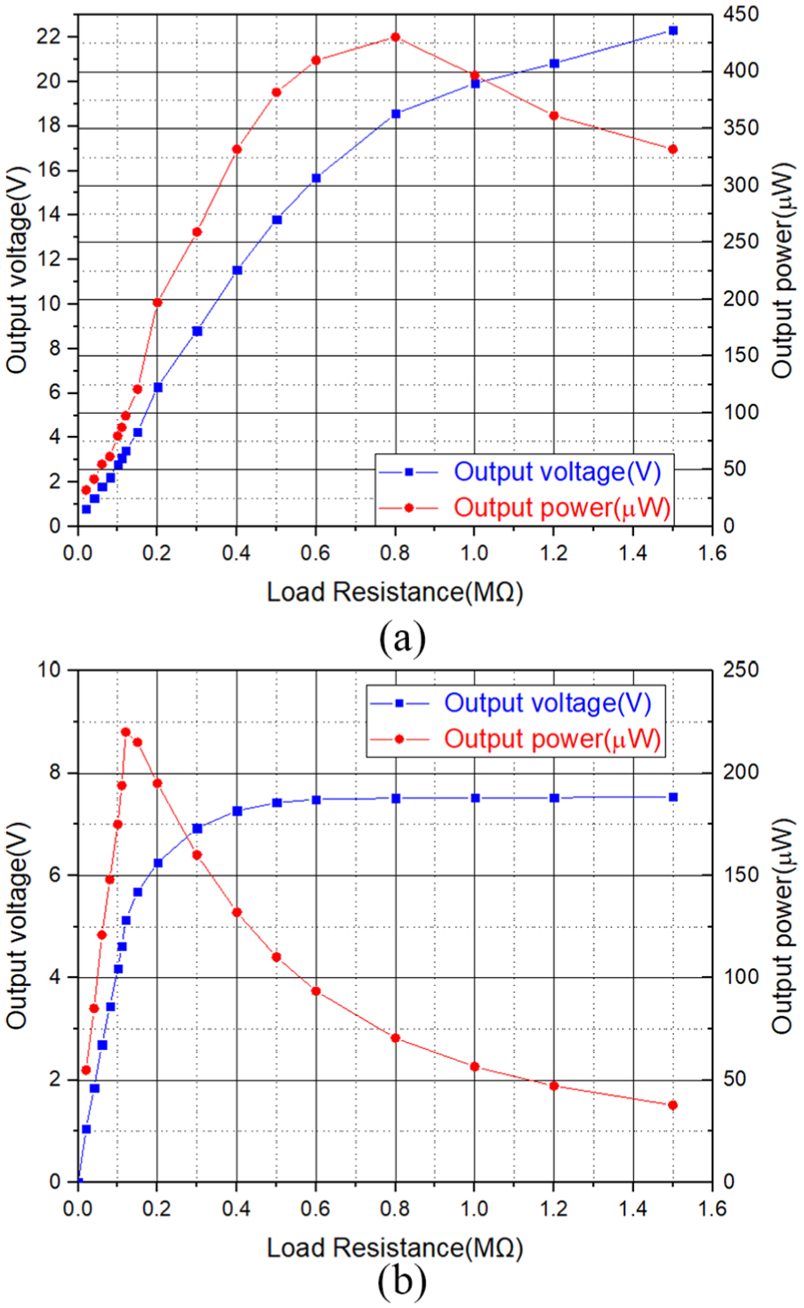
Electrical output power and voltage of the fabricated generator versus load resistance of (a) series stack and (b) parallel stack.
Conclusion
This article presents the following conclusion and prospect through analysis, which provides a more practical method for the design of a compliant amplifier. Initially, the PRB method is used to develop the conceptual design, considering the compliant structure to be equivalent to a composite structure consisting of a rigid body and an ideal spring. Subsequently, the parameters of the compliant structure are obtained, and the selection and configuration of the compliant hinge is carried out according to the result of the solution.
In addition, it realizes the topology optimization of the assumptive ideal rigid body of the compliant structure. The final compliant structure is obtained by establishing reasonable objective functions and constraints, and the above part is verified by the finite element method and related experiment. Compared with the traditional design process, this method emphasizes the flexibility of the design.
Finally, the compliant amplifier designed by the above method is applied to the piezoelectric energy collection system. First, it makes a simple piezoelectric stack that is suitable for application under a low frequency load. Then, the piezoelectric stack is combined with the flexible load compliant amplifier, and these parts are integrated into the bicycle pedal through a lever. Subsequently, it tests the pedal model. The result shows that the structure can reach the maximum power of 230 µW under the load of 110 kΩ in parallel stack mode and 427 µW under the load of 800 kΩ in series stack mode when the exciting load increases at 15 N and frequency is 1 Hz, which can effectively drive a low-power microcontroller, low power sensor, and other devices of this kind.
Footnotes
Handling Editor: Yong Chen
Declaration of conflicting interests
The author(s) declared no potential conflicts of interest with respect to the research, authorship, and/or publication of this article.
Funding
The author(s) disclosed receipt of the following financial support for the research, authorship, and/or publication of this article: This work was supported by the Human resource development for construction equipment R&D business grant funded by the Korea government (MOTIE).