
Abstract
Worldwide, high-speed rail is becoming an increasingly popular and efficient means of transport. However, increasing the speed of a train leads to major reductions in stability and ride comfort. Here, we develop a tubular permanent magnet actuator to overcome these problems. To increase actuator thrust, the electromagnetic circuit requires a high current and, thus, becomes hot. We use a water cooling system with 12 straight copper channels to reduce the temperature. We calculate heat transfer coefficients using empirical convection correlations between laminar flow in the channels and experimental results. The predicted, tube surface temperatures correlated well with the experimental data. We evaluated the effects of flow rate and initial water temperature on various design parameters. The cooling system allowed application of a current greater than 100 A, developing a thrust force of over 8000 N. Thus, the system was robust under harsh operating conditions. We measured the thrust and cogging forces and the performance of the water cooling system in terms of the maximum acceptable temperature. The thrust was high and the cogging torque was low, greatly reducing lateral vibration; the temperature remained below the acceptable maximum.
Keywords
Introduction
Generally, a high-speed train is defined as one that operates at speeds of over 200 km/h (124 mile/h). Such trains have been emerging across the world as an increasingly popular and efficient means of transport. For these reasons, many countries have become interested in the development of high-speed trains since the early 2000s. Recently, the TGV in France recorded a top speed of 575 km/h (357 mile/h), China Railways’ Shanghai Maglev recorded a top speed of 501 km/h (311 mile/h), the KTX in Korea was developed as high-speed train with a top speed of 421 km/h (262 mile/h), the ICE in Germany recorded a top speed of 368 km/h (228 mile/h), and the AVE in Spain recorded a top speed of 404 km/h (251 mile/h). 1
Although all the high-speed trains mentioned above have a top speed of over 350 km/h, the maximum operating speed of high-speed trains is generally below 70% of the top speed. This is because a full train was not used when exploring the top speed, and the lateral and vertical vibrations of the train are exponentially increased by the high air flow power and by high-level irregularities between wheels and rails at high speeds. Thus, increasing the speed of a train causes a major reduction in its stability and ride comfort. Therefore, it is essential to restore the stability lost to vibration (especially the lateral vibration related to derailment).
Recently, various types of suspension have been developed to reduce the lateral vibration of high-speed trains. Semi-active suspension systems using variable electro-hydraulic proportional valve dampers 2 or magneto-rheological dampers 3 have been developed and applied to the whole train system. In addition to semi-active suspension, active lateral secondary suspension using permanent magnets 4 and pneumatic or oil hydraulic actuators have been studied. Lateral acceleration has been drastically decreased and the riding comfort improved using active lateral suspension systems. Of these, hydraulic actuators can be easily installed in the narrow space between the car body and the bogie. 4 However, it is difficult for them to attenuate various vibrations induced by sources exhibiting wide frequency spectra due to a low control bandwidth. Other disadvantages include a serious leakage problem, and a high sensitivity to temperature. Moreover, a highly complex controller design is required to deal with the extensively nonlinear dynamics of the hydraulic actuator. 4 In comparison, active lateral suspensions using electromagnetic (EM) actuators exhibit good frequency responses and sufficiently high power and thrust force. In addition, there are many optimized and mature controller algorithms applicable even under nonlinear conditions. However, a high thrust power and a low cogging toque are essential when such actuators serve as active dampers in high-speed trains because of the heavy train body and the frequent loss of power. To increase the thrust force of the EM actuator, high current should be applied to the EM circuit because of the linear relation between the thrust force and the current. Such high currents increase the temperature inside the EM circuit. The demagnetization thus induced reduces the actuator thrust power and increases the risk of fire. Therefore, cooling of the EM circuit is essential to retain high thrust power when applying a high input current. An efficient cooling system can be used to ensure the performance of the secondary suspension required for the safety of a high-speed train.
To verify the thermal behavior of a cooling system, many researchers have resolved complex problems by identifying the encountered thermal phenomena and the heating sources and then building appropriate thermal models.5–8 Based on these simulation models, I Vese et al. presented a multi-physics model based on finite element coupled EM and thermal field analysis. They constructed a sequential magneto-thermal coupling model using a transient thermal equivalent-circuit model. 9 D Staton et al. provided guidelines for choosing suitable thermal and flow network formulations and setting any calibration parameters. These heat transfer and flow formulations were successfully applied to the thermal analysis of electrical machines.10,11 However, the practical performance of a cooling system operating in conjunction with a tubular permanent magnet actuator (TPMA) when a high thrust is generated by a high input current has not been experimentally investigated.
In our previous research, we explored air cooling effects in high-speed trains (using forced convection). 4 However, it is difficult to apply air convection cooling to a real high-speed train because of the difficulty involved in making an effective air channel between the car body and the bogie. This narrow gap contains complex structures that block air flow and decrease the passing air speed despite the fact that the train is operating at high speed. Therefore, it is necessary to apply a more efficient and robust method to lower the temperature of the EM circuit.
In this article, the water cooling system is proposed as a means of effectively reducing the inside temperature of an EM circuit. Specifically, we designed straight water channels (circular tubes) within a TPMA. A TPMA containing a water cooling system featuring copper channels was then fabricated. The heat transfer coefficients were then calculated using empirical convection correlations related to the flow motion in the circular channels and were validated through experimentation on the fabricated TPMA featuring various input currents. The effects of various cooling system design parameters, such as the flow rate and initial water temperature, were investigated. Finally, the maximum thrust and cogging forces of the TPMA were evaluated when an appropriate water cooling system was applied, and feasibility in terms of water-forced convection was experimentally verified.
Flow characteristics inside the circular water channel
Convection heat transfer coefficients are often calculated using empirical formulations based on convection correlations; these are readily available in the heat transfer literature.12–14 As the forced convection heat transfer from a given surface depends on the local fluid velocity,7,15–19 both velocity and water temperature must be considered. When analyzing the thermal features of TPMAs fitted with cooling systems, two thermal behaviors are generally considered. One features natural air convection, caused by density differences attributable to the temperature gradients between the external surface of the TPMA and the environment. The natural convection coefficient was 3.3 W/m2 K in our previous test. 4 The other behavior features forced coolant convection attributable to the behavior of the cooling water. Here, we ignored the air-forced convection effect because the effect thereof was much smaller than that of water-forced convection. Heat transfer coefficients can be obtained using empirical correlations. Generally, heat transfer coefficients are empirical non-dimensional numbers, such as the Reynolds number Re, the Prandtl number Pr, the Nusselt number Nu, and the Grashof number Gr; these are calculated as follows
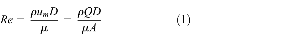


where ρ is the fluid density (kg/m3), D is the diameter of the circular channel, um is the channel flow velocity, Q is the flow rate (L/min, LPM), A is the cross-sectional area of the channel (m2), cp is the fluid-specific heat capacity (kJ/(kg K)), μ is the fluid dynamic viscosity (Ns/m2), k the fluid thermal conductivity (W/(m K)), h the heat transfer coefficient (W/m2 K), β is the coefficient of thermal expansion (1/K), g is the gravitational attraction force (m/s2),

The number is large at the entrance region, but asymptotically approaches the fully developed value of 3.66 as L→∞ when laminar flow is in play in a circular tube of uniform surface temperature.
Experimental setup
Experimental setup and configuration
In our previous research, 4 the active lateral secondary suspension was optimally designed using a moving magnet-type Halbach magnet array and slotted core, which can generate a higher thrust force because of the magnetic field generated by the interaction between the magnets and cores. The translator consisted of segmented magnets, a yoke, and a shaft as shown in Figure 1(a). The stator consisted of five pairs of three-phase coils, with a laminated core and aluminum housing. The permanent magnet is a N46H, the core and yoke are made of a silicon steel, and the coil is made of copper. Figure 1(b) shows the fabricated TPMA, and Table 1 lists the design parameters and specifications. The maximum temperature was limited to 130°C considering the demagnetization of Halbach magnets. The total weight of the fabricated TPMA was 108 kg, and the axial length was 1 m. The maximum stroke was determined using a real train running on two test lines at different maximum velocities (130 and 210 km/h); we used passive dampeners to this end. 4 The damper velocities and displacements were generally under 0.05 m/s and 0.01 m, respectively. The maximum displacement and velocity were 0.04 m and 0.22 m/s, respectively. Thus, we set the maximum moving stroke to ±0.05 m (we incorporated a safety factor). The displacement and velocity of the lateral passive damper indicated that the thrust was greater than 8000 N.

Overall structure of the TPMA and fabricated TPMA: (a) TPMA configuration and (b) fabricated TPMA.
Specifications of the TPMA.

TPMA: tubular permanent magnet actuator.
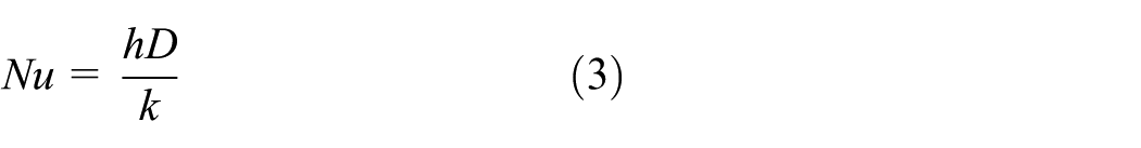
Figure 2 shows the experimental setup to measure thermal characteristics, thrust, and cogging forces. The system consists of a 7-kW power supply, inverter, and solid-state relay (SSR). A ball screw motor, which is serially connected to the load cell (LS-2, repeatability of 0.01%) and the shaft of the mover, was installed to measure the cogging and thrust forces. The mover stroke was measured using a potentiometer and a laser doppler vibrometer (LDV) affording nanometer-scale resolution. The input current was measured using a current meter of range 0–200 A with a resolution of 0.1 A. We employed calibrated load cells and thermocouples to measure the cogging and thrust forces and the internal temperature prior to the experiment. The temperature ranged from 5°C to 130°C, and the force ranged from 0 to approximately 8500 N. A data acquisition system (data logger) was used to secure the temperature data from the thermocouples embedded in the TPMA. The data are summarized in Table 2. Figure 3 shows the water cooling system. The water cooling system, consisting of 12 serially connected circular copper pipes, is embedded in the TPMA core. The inner diameter of each pipe is 3.6 mm, and the length of each pipe is 560 mm. The air cooling system consists of natural convection, which interacts with the annular fins that are circumferentially attached to a cylinder and designed to enhance heat transfer from the surface to the surrounding fluid. The fin height and pitch are 9 and 7 mm, respectively. The schematic of the water cooling system is illustrated in Figure 4. A chiller using a vapor-compression system maintains the constant temperature of the cooling water that flows through the 12 circular copper pipes connected in series. Two rotameters were installed to measure the flow rate of the cooling water at the inlet and outlet channels. To estimate both the axially and radially transmitted heat, we used six thermocouples on the V3 phase coil and the W5 phase coil. These were placed on the outer coil surfaces and outer heat sink surface, and were embedded in the TPMA as shown in Figure 5. In addition, four thermocouples were used to measure the ambient temperature, copper pipe temperature, inlet water temperature, and outlet water temperature.

Experimental setup of TPMA.
Measurement devices.

Annular fin, cooling channels, and chiller.

Schematic of water cooling test.

Points measuring the temperature.
Uncertainty analysis
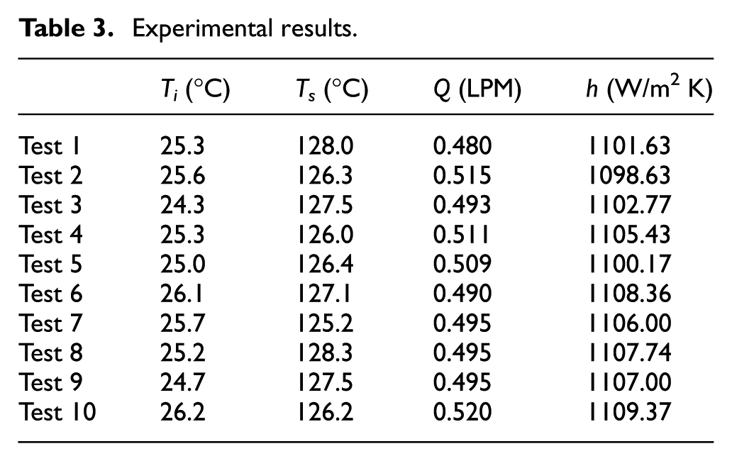
We performed uncertainty analysis based on the American Society of Heating, Refrigerating and Air Conditioning Engineers (ASHRAE) guidelines 22 and the literature.23–27 The overall uncertainty of the convection coefficient (equation (5)) was calculated based on the measured inlet water temperature (Ti), circular tube surface temperature (Ts), and water flow rate (Q); we derived error propagations (bh values) and random errors (ph values) (equation (6)). The combined standard uncertainty of propagation and random errors (multiplied by sensitivity factors) is given by equation (7). Table 3 lists the experimental data. All measurements were performed 10 times. Table 4 summarizes the overall uncertainties of the measured data. The coverage factor was 2 (considering the 95% confidence level)


Experimental results.
Overall uncertainty of measured data.

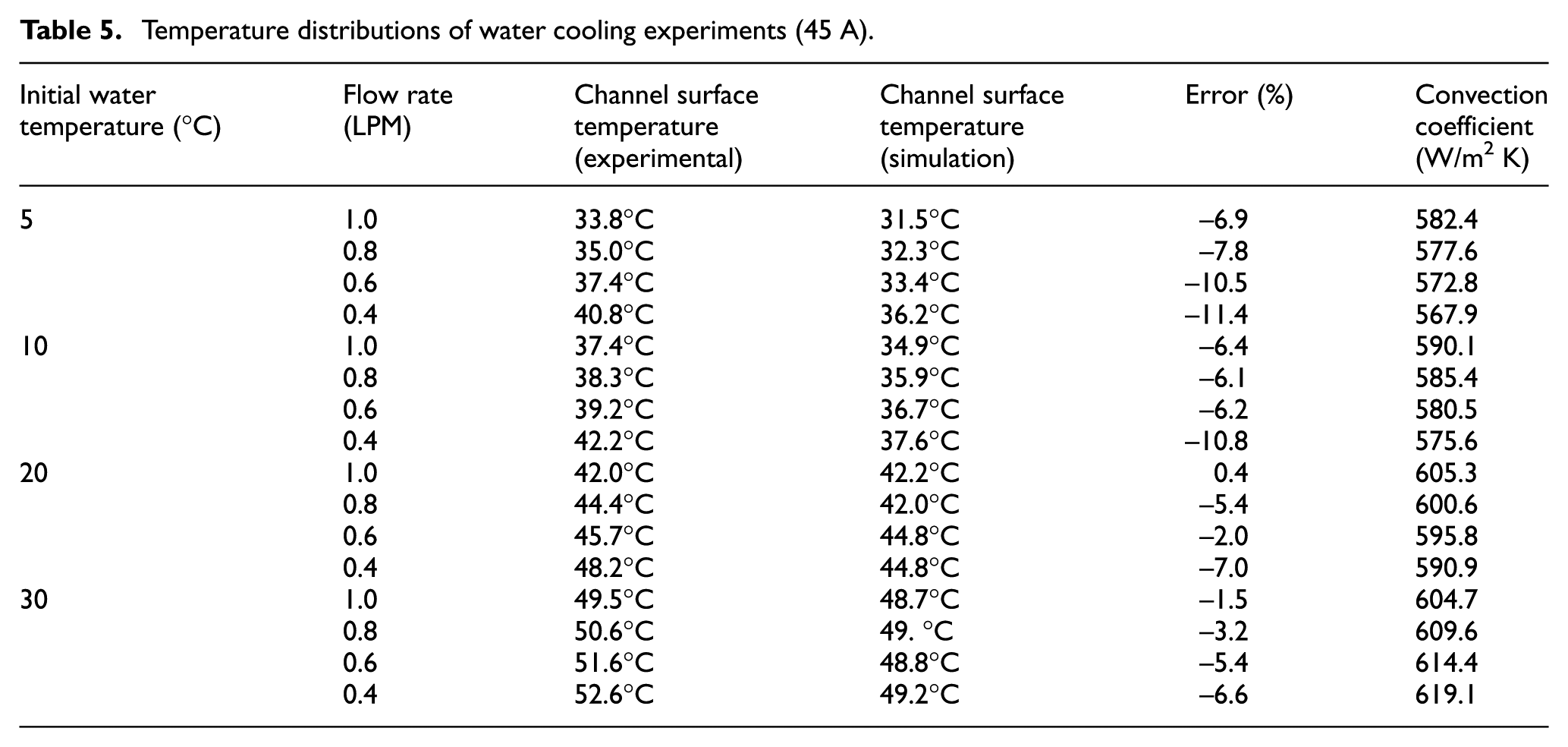
Experiments were conducted to investigate the thermal characteristics of the water cooling effect for various initial water temperatures and flow rates. Most of the heat diffused much faster than did the momentum flow through the water channel surfaces because the flow was always laminar and water has a low Prandtl number. 28 First, the tests were carried out for an input current of 45 A corresponding to a thrust force of about 3700 N, for initial water temperatures from 5°C to 30°C and initial flow rates from 0.4 to 1.0 LPM. The experimental results are shown in Figure 6. As the initial water temperature increased from 5°C to 30°C, the maximum temperature in the coil (corresponding to the surfaces of the circular channels) also increased, but the increments decreased. This was because the lower the initial temperature, the greater the temperature difference between the bulk and the surface of the water channel, improving cooling. However, a dramatic reduction in the cooling performance was evident at higher initial water temperatures. The cooling efficiency increased linearly with increasing flow rate because it introduces more water molecules, which act as a medium to absorb the heat. The experimental details are summarized in Table 5. Based on the flow characteristics in the water channel, the heat transfer coefficient can be calculated using an empirical formulation (equation (5)). The calculated heat transfer coefficients are summarized in Table 5. When the initial temperatures ranged from 5°C to 30°C and the flow rate ranged from 0.4 to 1.0 LPM, the heat convection coefficients are approximately 570–620 W/m2 K. The temperatures predicted using the calculated coefficients agree with the experimental results, and the errors were less than about 11%. The errors are attributable to the fact that we calculated heat convection coefficients considering only water-forced cooling convection (thus, not air convection) and we ignored the small bent region connecting the water channels. The bent region may render the flow less than fully developed throughout the entire channel; some regions may feature combined points of entry. Also, a small amount of heat transfer may occur in the bent region. However, the errors are very small, being less than about 5% under our experimental conditions (initial temperature 25°C and flow rate 0.5 LPM). Thus, our derived heat convection coefficients were appropriate. The water cooling efficiency is approximately 24 times higher, as compared to an air-forced convection coefficient of 26 W/m2 K at a flow speed of 8 m/s. Therefore, our water cooling system was extremely effective in terms of reducing the inside temperature.

Experimental results of water cooling (45 A).
Temperature distributions of water cooling experiments (45 A).
The same experiment was carried out for the case of an input current of 90 A corresponding to a thrust force of almost 8000 N. We explored whether the cooling system worked well if the thrust was over 8000 N. The convection coefficients calculated theoretically for an input current of 45 A were used in this experiment. The thermal characteristics were measured through an experiment, as shown in Figure 7. As shown in Table 6, the inside EM temperatures decreased linearly with increasing initial temperature, as in the previous test. The large temperature variation within the EM is attributable to the significant temperature difference induced by the high input current. This decreased exponentially as the water flow rate increased. For the case of a flow rate of 1.0 LPM and an initial temperature of 5°C, the internal temperature is decreased by up to 80°C. Thus, the cooling system worked well when a thrust force of 8000 N was achieved by applying a current of 100 A.

Experimental results of water cooling (90 A).
Temperature distributions of water cooling experiments (90 A).

Investigation of the performance of the TPMA with a water cooling system
Using the aforementioned experimental setup (see Figure 2), we measured thrust forces, cogging forces, and maximum temperatures with an increasing current to the locked TPMA. The water cooling system was set at an initial temperature of 25°C and a flow rate of 0.5 LPM, and the temperature was measured for about 1.6 h. We chose an initial temperature of 25°C because this reflects the normal operation of a high-speed train. Figures 8–10 show the experimental results. First, as shown in Figure 8, the measured thrust force is linearly increased with input current in both the positive and negative directions. As predicted in a previous study, the thrust force is over 8000 N when the input current reaches 100 A; no saturation was evident. In this case, the cogging force with a 40-mm period (20 mm) is measured while the mover is slowly moved using a ball screw motor, as shown in Figure 9. It is confirmed that the maximum cogging force (about 200 N) is very low compared with the maximum thrust force. Moreover, as cogging forces remain near-identical at given positions, the cogging force ripple can be compensated using a simple control algorithm. While the maximum thrust force of 8000 N was achieved, the temperature was measured, as shown in Figure 10. The measured temperature was almost saturated after 20 min, and the maximum temperature was 130°C in the V coil; this is safe (Table 1). The temperatures of other components remained under 70°C throughout the entire evaluation. The target thrust force could thus be achieved using our water cooling system.

Thrust forces as a function of input current for positive and negative motions: (a) positive motion and (b) negative motion.

Cogging forces for positive and negative motions.

Temperature history measured inside of EM.
Conclusion
To compensate for the deterioration in riding comfort caused by the increased vehicle speed and inferior track conditions, we developed a TPMA featuring a water-forced convection cooling system; this served as an active secondary suspension. We first fabricated a TPMA with 12 circular copper tubes to investigate the feasibility of such a system in terms of TPMA thrust and cogging forces. We then built an experimental setup and subjected temperatures, flow rates, and heat convection coefficients to uncertainty analyses. These showed that our experiments were appropriate in terms of investigating heat transfer performance. In the water cooling experiments, it was observed that the effects of water cooling linearly varied with water temperature and exponentially decreased with increased flow rate. The heat convection coefficients obtained using an empirical formulation agreed with the experimental results. The heat convection coefficients of the water cooling system were about 24 times higher than those of an air-forced convection system. As a result, this experiment proved that a water cooling system is more effective than an air convection system and our cooling system allowed the use of the TPMA in a high-speed train. The thrust force was over 8000 N and the cogging torque was low; temperature and performance constraints were met. The system can be used to improve the stability and ride comfort of high-speed trains.
Footnotes
Acknowledgements
Handling Editor: ZW Zhong
Declaration of conflicting interests
The author(s) declared no potential conflicts of interest with respect to the research, authorship, and/or publication of this article.
Funding
The author(s) disclosed receipt of the following financial support for the research, authorship, and/or publication of this article: This research was supported by a grant (17CTAP-C133353-01) from Technology Advancement Research Program (TARP) Program funded by Ministry of Land, Infrastructure and Transport of Korean government.