
Abstract
Aiming at how to specify the fundamental trade-off between robust stability and nominal performance of mixed H2/H∞ control as well as lack of experimental studies on vibration control for the maglev actuator in microgravity vibration isolation system, a mixed H2/H∞ output feedback controller based on the linear matrix inequality method is designed and analyzed. This article establishes a state–space realization for a one-dimensional vibration isolation system and the H-norm performance indices are identified and calculated. Furthermore, the curves of threshold values and true values of H∞ and H2 norms are plotted to specify the relationship between the system’s robust stability and nominal performance. Therefore, the threshold value of system’s H∞ norm is identified through repeated simulations, and the state–space realization of optimal controller with minimum H2 norm under the constraints of H∞ norm threshold value is obtained. The vibration control experimental apparatus of one-dimensional control system is designed and manufactured to test the actual application of mixed H2/H∞ controller for the maglev actuator. The result presents that the designed mixed H2/H∞ control has a better performance in suppressing acceleration vibration and has a higher attenuation amplitude than cascade proportional–integral–derivative control at each corresponding frequency, which proves the practicability and effectiveness of the design method.
Keywords
Introduction
Spacecrafts are subjected to internal perturbations and the disturbances caused by external environment while traveling on its orbit. These disturbing sources are featured with small amplitude, wide frequency range, and diverse vibration modes, and so on, which would seriously affect the microgravity acceleration level of experimental payloads. 1 Depending on the sources and natures of disturbances to spacecrafts, the microgravity acceleration mainly includes quasi-steady-state acceleration, vibration acceleration, and transient acceleration, among which the impact of latter two on many space science experiments is difficult to be analyzed by detecting in a variety of missions and has become the research hotspot of vibration isolation. 2 To minimize the impact on the experimental payload, the active vibration isolation technique is leading the trend for microgravity vibration isolation development, which could effectively isolate the disturbance as low as 0.01 Hz. Since 1990s, several active systems have been developed successfully to address microgravity vibration isolation problems, such as Active Rack Isolation System (ARIS), 3 Microgravity Vibration Isolation Mount (MIM), 4 Glovebox Integrated Microgravity Isolation Technology (G-LIMIT), 5 and MIM Base Unit (MIM-BU). 6 These systems are featured with large stroke, high precision, and good low-frequency vibration isolation performance, and so forth. In addition, their vibration isolation units are all self-designed Lorentz-force actuators.
In order to address low-frequency vibration isolation problems of microgravity vibration isolation platforms within finite stroke, control methods applied to payload-level isolation systems mainly include proportional–integral–derivative (PID) control, sliding-mode control, H2-optimal control, H∞ robust control, mixed H2/H∞ control, and optimal control.7–10 Liu et al. 11 designed an inertia electromagnetic actuator capable of adjusting the natural frequency so as to overcome the limit to a very narrow bandwidth around the natural frequency of the conventional inertia electromagnetic actuator. Although the isolator presents a very good vibration isolation performance in a broad frequency range, its structure is complex and bulky. Yang et al. 12 added the neural network to the PID controller to improve the system performance in case of the uncertain model parameters. Shkolnikov et al. 7 considered the impact of high-order dynamic characteristics of sliding mode on the performance of microgravity vibration isolation system and proposed a high-order sliding-mode control method. When the system parameters changed by 20%, the same attenuation effect was achieved, but the settling time increased from 20 to 30 s. In addition, the steady state of the system was not sensitive to parameter changes. H∞ robust control considers the uncertainties of the system and structural parameters, has good ability of robustness and anti-interference, and has been successfully applied in ARIS rack-level isolation system. 13 Song et al. 14 designed a H∞ controller with the shaping design method based on mixed sensitivity problem for a MIMO (multiple input, multiple output) system to suppress single frequency-varying disturbance and the experiment results and the numerical simulation results are basically in line, indicating a good vibration isolation effect. Hampton and Whorton 15 and Calhoun and Hampton. 16 adopted a one-dimensional vibration isolation system and effectively solved the kinematic coupling problem in the course of designing frequency-weighted filters. On this basis, Whorton 17 discussed the impact of different frequency weighting functions on the current and performance of a one-dimensional vibration isolation system. Calhoun and Hampton 18 applied the H2-optimal control to a 6-degree-of-freedom (DOF) microgravity vibration isolation system. Whorton 19 designed a 12-order mixed H2/H∞ mixed controller which displaced a 54-order H2 controller for the 6-DOF microgravity isolation system. To guarantee system’s robust stability as well as controller’s order constraints, the system performance only slightly decreases, but the system stability increases substantially. Karimi 20 develops an efficient convex optimization approach to design the delay-dependent observer-based mixed H2/H∞ state feedback controller which could be applied to linear systems with time-varying state, input, and output delays. Karimi and Gao 21 develop an efficient approach to design the delay-dependent mixed H2/H∞ output feedback controller which could be applied to second-order neutral linear systems with time-varying state and input delays. Qiu et al. 22 investigate a data-based optimal control for a class of networked industrial processes with a double-layer architecture, and the structures are with the feature of network-induced time delay, packet dropouts, and packet disorder in both uplink and downlink channels. The research content of the above literature would help us to design and optimize the controller of active vibration isolation system, as well as to achieve the control of spatial orientation and location tracking.
PID control belongs to the classic controlling method, which is used for MIMO system requiring adequate decoupling as a precondition. The design of decoupling controller relies on the accurate measurement of system’s parameter matrix while it cannot be fully decoupled because of structural parameter uncertainty and non-linearity, which limit the application of PID control method.23,24 Although H2 design could acquire good nominal performance, the controllers are highly tuned to the design model and errors in the design model are not accounted for, typically inducing instability in the presence of slight parameter variations with high authority controllers. H∞ robust control allows for the uncertainties of the system and structural parameters; it has good ability of robustness and anti-interference. However, H∞ robust control is mainly concerned with frequency domain performance while could not guarantee the linear quadratic regulator (LQR) performance of vibration control in the time domain; therefore, it could not satisfy with the requirement of system’s performance very well. 25 Mixed H2/H∞ control based on the linear matrix inequality (LMI) method could balance between robust stability and nominal performance by specifying the H2/H∞ constraints and criterion, which makes it possible to adequately capture multiple design specifications. Moreover, it could also allow for direct placement of the closed-loop poles in more specific regions of the left-half plane, which is related to the time response and transient behavior of closed-loop systems. However, mixed H2/H∞ control needs to identify the relationship between system’s nominal performance and robust stability. Most of the previous research works on the actuator control method are limited to simulations, and there are few relevant experimental research works.
This article aims to design a mixed H2/H∞ output feedback controller based on LMI method for a maglev actuator of microgravity vibration isolation platform; thus, further study was carried out to the dynamic modeling, controller design, and vibration control experiments. The main contents of this study are as follows: the state–space realization is established according to an equation of motion (EOM) for the one-dimensional vibration isolation system in section “Structure and mathematical model of the actuator.” Section “Establishment of H2/H∞ output feedback controller” selects H2 and H∞ performance indices for the vibration isolation system and establishes a state–space realization of the augmented plant. In section “Study on multi-objective output feedback controller,” the MATLAB functions (hinfmix, normh2, and normhinf) are adopted, respectively, to compute the threshold values and true values of H∞ and H2 norms for the closed-loop system. Whereafter, the curves of threshold values and truth values are plotted to specify the relationship between the system’s robust stability and nominal performance, and the state–space realization of optimal controller with minimum H2 norm under the constraints of the H∞ norm is obtained and the influence of structural parameters (M and K) on the H2 and H∞ indices is analyzed. In section “Verification of vibration control performance,” mixed H2/H∞ control is compared with cascade PID control in the performance test of the one-dimensional vibration isolation system. Experimental results show that mixed H2/H∞ control has a better performance in suppressing acceleration vibration and has a higher attenuation amplitude than cascade PID control. Section “Conclusion” concludes the article.
Structure and mathematical model of the actuator
Vibration isolation system
Microgravity vibration isolation platform is a very important device to isolate experimental payloads from various vibrations which are present on the manned space station. By sensing the motion of the payloads which is sensitive to acceleration, the active control system generates a certain force or torque to payloads by manipulating actuators in a real-time manner. As the controller parameters and dynamic vibration isolation effect could be easily adjusted, the acceleration level of the experimental payload would be guaranteed. A payload-level active vibration isolation scheme was put forward, whose structure is shown in Figure 1. The vibration isolation platform is mainly composed of a floater and a stator, both of which are connected by umbilical cables. The stator consists of a baseboard and an annular side plate, while the floater mainly accommodates experimental payloads. The platform adopts three self-designed Lorentz-force actuators, which mainly include a coil component and a yoke component. The coil component has two mutually orthogonal coils elements to generate horizontal and vertical forces, respectively. The stator contains three position-sensitive detectors (PSDs) and three coil components. Three yoke components of the actuator and three sensor modules are installed at the bottom of the floater. Each sensor module includes a laser source and two mutually perpendicular accelerometers.

Schematic diagram of microgravity vibration isolation platform.
The only mechanical connection between the floater and stator is a set of umbilical cables that are the only load path for vibration disturbance to the platform; an active isolation system must sense and cancel the acceleration of the experimental payload. Consider a one-dimensional vibration isolation system having the arrangement depicted in Figure 2, and the disturbance caused by the stator displacement is mainly transmitted through the umbilical cables to the experimental payload. The umbilical cables are modeled here as a linear element with stiffness (K) and damping (C). The actuator not only isolates external disturbances but also suppresses inertial disturbances to guarantee the acceleration level of the experiment payload. It can be assumed that the actuator is linear within the operating frequency range and the current-to-force gain is
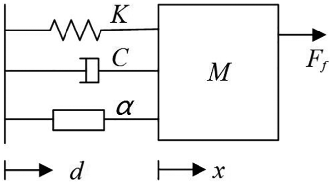
SDOF vibration isolation system.
State–space realization of the system
The horizontal rightward direction is set as the positive direction. From Figure 2, the EOM for the system is as follows

Define the following states


The EOMs can be written in standard state–space form

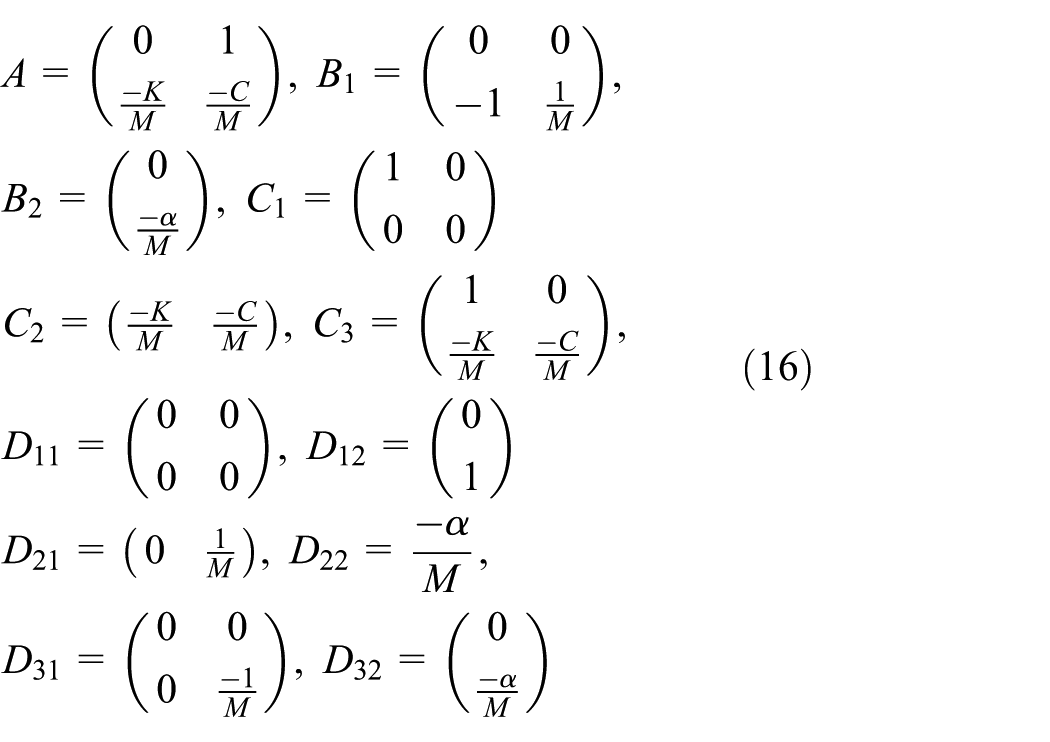
where

Establishment of H2/H∞ output feedback controller
Problems related to H2/H∞ closed-loop control
In many real-world applications, the designed system needs to meet multiple performance requirements. This makes multi-objective synthesis highly desirable in practice, and the LMI theory offers powerful tools to attack such problems. Mixed H2/H∞ feedback control mainly includes state feedback and output feedback. If the system state could be all measured, a static state feedback controller can be designed directly. As all states of the system often cannot be measured in practice, it is more suitable to select the output feedback control for plants. Therefore, the study on output feedback control is more practical. Moreover, mixed H2/H∞ control based on LMI method could indicate the relationship between robust stability and nominal performance by specifying the H2/H∞ constraints and criterion, which makes it possible to adequately capture multiple design specifications. Moreover, it could also allow for direct placement of closed-loop poles in more specific regions of the left-half plane, which is related to the time response and transient behavior of the closed-loop dynamics.
The mixed H2/H∞ controller output feedback model is sketched in Figure 3, where

Mixed H2/H∞ output feedback control.
Design an output feedback controller
Place the closed-loop poles in the open left-half plane;
Maintain the H∞ norm of
Maintain the H2 norm of
Let

and

be state–space realizations of the plant
be the corresponding closed-loop state–space realization. Where
The design objectives can be expressed as follows:
H∞ performance. The closed-loop RMS gain from

H2 performance. The H2 norm of closed-loop transfer function from


A single Lyapunov matrix is assumed as follows

The mixed H2/H∞ controller model is primarily calculated by introducing the constrained condition (equation (14)) which could greatly simplify the process of solving the controller model. However, it also makes the results relatively conservative. The MATLAB LMI toolbox provides the function hinfmix implements the LMI approach to mixed H2/H∞ output feedback control problems.
Establishment of state–space realization of the generalized plant
The H2 norm squared of system’s transfer function equals total output energy of the impulse response. It could also be expressed by the steady–state output variance of the system excited by white noise input signal. The H∞ norm of the system’s transfer function represents the peak of the largest singular value of system’s frequency response. Besides, the system’s H2 norm and H∞ norm correspond to the area below the amplitude curve and the peak of the curve in Bode diagram, respectively. Microgravity vibration isolation platform needs to isolate the external disturbance from the stator as well as to suppress the inertial perturbations generated by the experimental payload. The acceleration level of experimental payload is an important index for evaluating the performance of the vibration isolation system. Moreover, the constraint factors of the maglev actuator (namely, control current and effective stroke) also need to be considered.
To ensure that the acceleration level of experimental payload has a small energy distribution in low-frequency range of interest as well as the actuator is constrained by the current and stroke, in this article, the absolute acceleration
Let
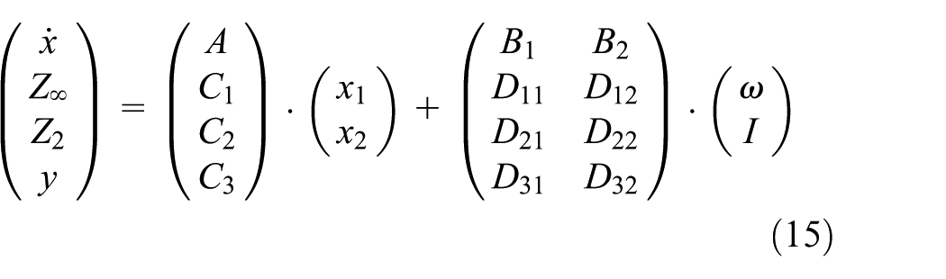
where
Because of

Let

Assume that

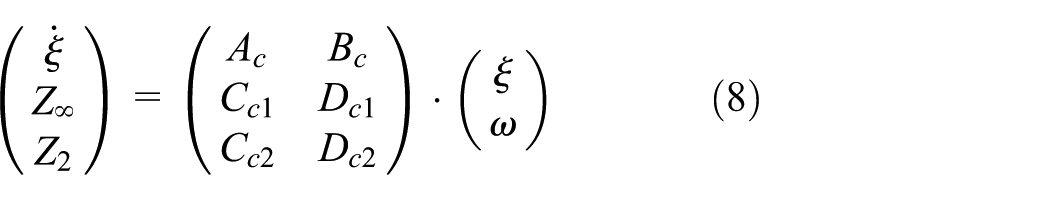
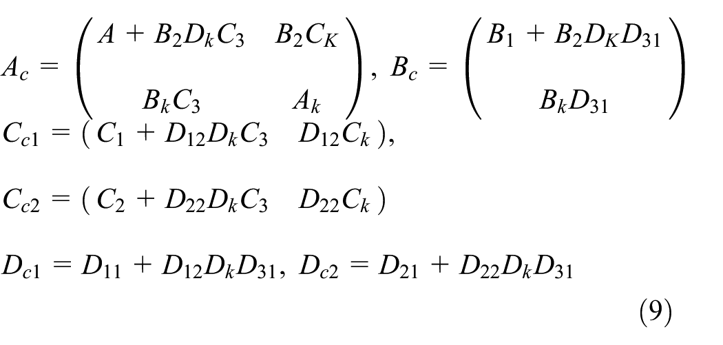
be state–space realizations of controller. After the controller’s parameter matrix is computed, replace

Similarly, the parameter matrixes
Study on multi-objective output feedback controller
Computation of mixed H2/H∞ output feedback controller
In this article, the structural parameters (payload mass M, umbilical stiffness K, and current-to-force gain
The instruments required to measure the stiffness of umbilical cables mainly include a force sensor, a digital amplifier, a 3-DOF displacement platform, a controllable voltage/current source, a data acquisition machine, and a PC. The experimental devices and rig are shown in Figure 4, where four power cables with 1 mm diameter and 300 mm length are selected as umbilical cables and their two ends are rigidly bonded to the force sensor and 3-DOF displacement platform, respectively, by cyanoacrylate adhesive, of which the connections are kept horizontal with the horizontal plane. After measurement, the average stiffness of umbilical cables is 6.02 N/m when the displacement platform moves horizontally within ±12 mm and a small value was given to the umbilical damping, which is 0.1 N/(m/s).
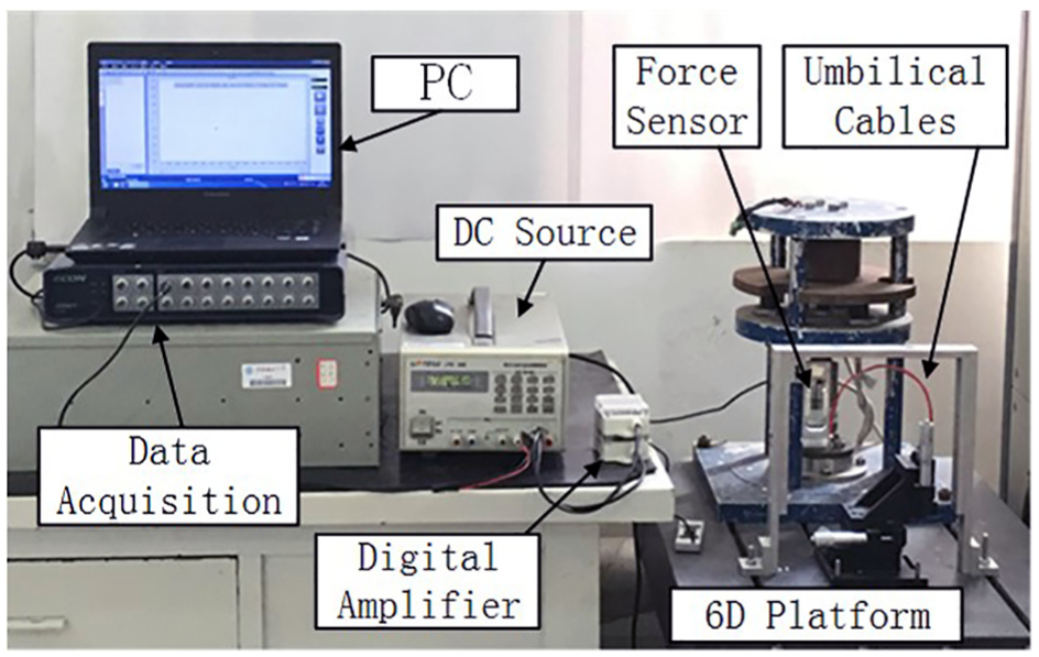
Umbilical cables’ stiffness test rig.
In the static calibration experiment, the output force was recorded when different currents were flowed into the coil of actuator. As the output force

Relationship between the force and the current.

Frequency characteristic of the actuator.
The system parameters are as follows:
Floater mass: M = 0.802 kg;
Umbilical stiffness: K = 6.02 N m;
Umbilical damping: C = 0.1 N/(m/s);
Actuator current-to-force gain:
In this article, the MATLAB function hinfmix is used as the main operating function for computation. Its syntax is as follows

where P is the SYSTEM matrix of the LTI plant
According to equation (16)
As the constraint condition (equation (14)) is introduced to simplify the solving process of inequalities equations (10)–(13), the threshold values of system’s H-norm have a certain conservative, by comparison, which is larger than the true values of its H-norm. In this article, the function hinfmix is mainly utilized to compute the threshold values of the H∞ and H2 norms of the closed-loop system. And then, functions normhinf and normh2 are used to compute true values of the corresponding H∞ and H2 norms. Therefore, the curves of the threshold values and true values of system’s H∞ and H2 norms could be plotted. Afterward, by analyzing the relationship between H∞ performance and H2 performance, this article indicates the relationship between system’s robust stability and nominal performance, and an optimal output feedback controller that meets H2 and H∞ performance requirement is obtained by repeated simulation experiments.
First, the function

is used to compute the threshold values of H∞ norm only within H∞-optimal design. The threshold value of H∞ norm of closed-loop system computed is 0.5972. The true value of H2 norm of closed-loop system computed using function normh2 is infinite at this time. And then, the function

is reused to compute the threshold values of H2 norm only within H2-optimal design. The threshold value of H2 norm of closed-loop system computed is 0.1031. And the true value of H∞ norm of closed-loop system computed using function normhinf is 3.0024 × 10⁴. It indicates that its robust stability is very poor at this time. As the true value of the H∞ norm is too large, which is difficult to accomplish in practice, the actuator is also limited by the control current and stroke. Therefore, the controller with minimum H2 norm is designed under the constraint of H∞ norm whose threshold values only varies from 0.6 to 100. Then, the function hinfmix is used to obtain the threshold values of system’s H∞ norm and H2 norm, and the functions normh2 and normhinf are used to compute the true values of the corresponding H-norms, respectively. Finally, the curves of threshold values and true values of H∞ norm and H2 norm are plotted, which is shown in Figure 7.

Curves of thresholds versus true values of H2/H∞.
It can be seen from the curves that only H∞-optimal design is performed in the controller design process; the minimized threshold value of system’s H∞ norm is obtained, which indicate that system has a very good robust stability. At the same time, the true value of system’s H2 norm is infinite, which indicates that its nominal performance could not be guaranteed. Furthermore, the H2 norm of the closed-loop system decreases gradually with the increase in the set threshold value of system’s H∞ norm. It indicates that the nominal performance of the system could be improved at the cost of its robust stability. As the threshold value of system’s H∞ norm increased, the H2 norm of system would become smaller and finally stabilized. Only H2-optimal design is performed in the controller design process; the minimized threshold value of system’s H2 norm is obtained, which indicates that system has a very good nominal performance. However, the true value of system’s H∞ norm is 3.0024 × 10⁴, and its robust stability is very poor at this time. Therefore, the determination of threshold value for designing a mixed H2/H∞ controller should consider the relationship between robust stability and nominal performance as well as the system’s constraints, and so on.
To ensure smaller energy distribution and lower frequency range, the required stroke and control current of the actuator should be increased. This is consistent with the relationship of the actuator stroke versus the acceleration and frequency
To guarantee the acceleration level of the experimental payload, the system’s H2 performance should be minimized under the constraint of the threshold value of H∞ norm. Considering that the control current and effective stroke of actuator do not exceed the maximum value (especially the actuator stroke cannot exceed ±10 mm), the appropriate threshold value of H∞ norm is set to 28. The computed true values of the H∞ norm and H2 norm is 27.1148 and 0.5971, respectively. The output feedback controller SYSTEM matrix is as follows

In the controller design process, on one hand, the relationship between robust stability and nominal performance has been determined primarily (the better the performance of the system is, the worse the robustness of the system is, and vice versa). On the other hand, there is a difference between the set threshold value and the true value of the closed-loop system. Therefore, during the controller design process, the designer could reasonably set the threshold value of the H-norm according to the performance requirements of the design (which could correspond to the size of H-norm) as well as the curves of threshold values and true values of H∞ norm and H2 norm of the closed-loop system. The plant needs to be transformed according to equations (17)–(20) if the
Impact analysis of parametric uncertainty to controller performance index
The model uncertainties mainly include the measurement error of structural parameters, the deviation between actual value and nominal value of structural parameters as well as the variation of the working condition, and so on. The influence of structural parameters (M and K), which vary from 50% to 150%, respectively, on the H2 and H∞ indices has been analyzed. Since the structure parameter C was set to a small value here, it is not considered. Tables 1 and 2 show the H-norms of
H-norm of

H-norm of
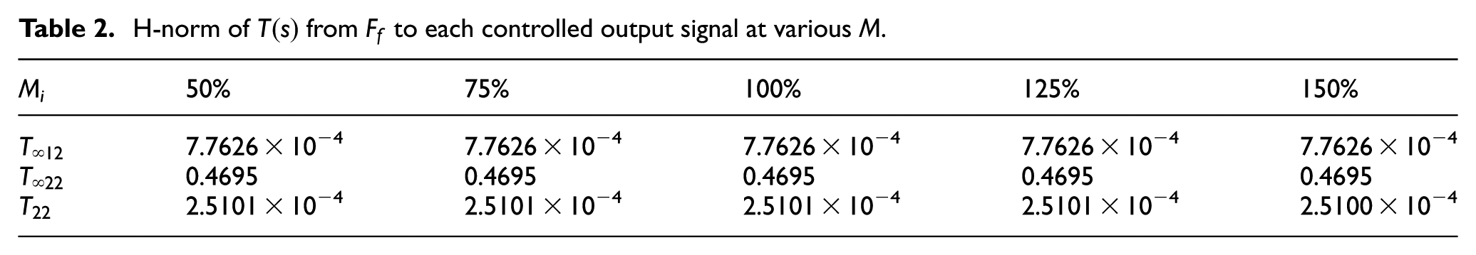
As can be seen from Table 1, the change of structure parameter Mi has no significant effect on the H-norms of

Step response from
Tables 3 and 4 show the H-norms of
H-norm of

H-norm of

As can be seen from Table 3, the change of structure parameter Ki has no significant effect on the H-norms of
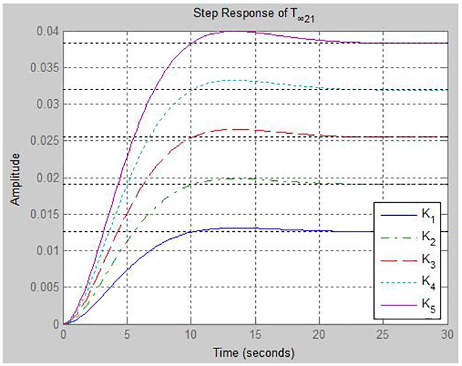
Step response from
The influence of the structural parameter (M and K) uncertainty on the H2 and H∞ indices is analyzed. From the results of simulation analysis, the changes of structural parameters (M and K) mainly affect the performance index from disturbance signal
Verification of vibration control performance
To investigate the actual application of the above-mentioned mixed H2/H∞ controller for active control of our maglev actuator, a one-dimensional active control experiment system is designed. Figure 10 shows the dSPACE-based real-time control system chart, which is composed of a PC, a dSPACE, a power amplifier, and a one-dimensional active control experimental platform. After the corresponding codes compiled from the simulation model in Simulink were imported into dSPACE, the A/D module of dSPACE was utilized to collect the signal from sensors. The control voltage was computed by control algorithm based on the collected data and transferred to the power amplifier, and control current is generated to control the actuator. In addition, the real-time revision of control parameters and the online data acquisition might be performed by utilizing the dSPACE ControlDesk Software. The above-mentioned actuator was tested to suppress vibrations from disturbance sources to verify the feasibility of mixed H2/H∞ control method for low-frequency vibration isolation.

dSPACE-based real-time control system chart.
Experimental device for one-dimensional vibration control system is shown in Figures 11 and 12. The device mainly consists of a self-designed actuator, a linear guide (THK L.S.P.2050), a quartz flexible accelerometer (SNJ-JB), a laser source, a PSD (PSD400-SPB), a vibration motor, a power amplifier (YE5874A), a spirit bubble, a bidirectional ampere meter, and a dSPACE DS1103 real-time simulation system. Among them, the spirit bubble indicates the inclination angle of the one-dimensional experimental device against the horizontal plane, and the horizontal position of the experiment baseboard could be finely adjusted with four screws. The coil component of actuator, linear guide, and laser source are fixed to the baseboard. The holder is mounted on the linear guide, which can be moved left and right along the horizontal direction. The yoke components of actuator, accelerometer, PSD, and vibration motor are mounted on the holder. Two ends of four power cables with 1 mm diameter and 300 mm length are rigidly bonded to the yoke and experimental support, respectively, by cyanoacrylate adhesive, of which connections are kept horizontal with the horizontal plane. The power cables with small stiffness and 0.25 mm diameter are adopted to connect the accelerometer and PSD, respectively, of which the arrangement is at the top of the experiment support to minimize their influence on the experimental effect.

One-dimensional vibration control experimental apparatus.

Control system experimental equipment.
The cascade PID control and mixed H2/H∞ control were adopted to the experimental subject in vibration control experiments. The cascade PID control system chart based on the dSPACE real-time control system is shown in Figure 13, where the outer loop is composed of the displacement feedback signal and displacement controller (or primary controller) of the experimental object. The inner loop is composed of the acceleration feedback signal and acceleration controller (or secondary controller) of the experimental object. When the payload generates any disturbing acceleration, the acceleration controller produces control signal in accordance with the deviation signal to counteract the inertial motion. As the floater may drift due to its acceleration, the primary controller regulates the setting of secondary circuit through its outer loop to adjust the initial acceleration; in addition, the secondary controller (or acceleration controller) not only receives output signals of the primary controller but also performs the corresponding regulation in accordance with the measurements of the accelerometer. Thus, the payload acceleration could track the varying setting and make timely regulation in accordance with the floater displacement, eventually bring it back to center.
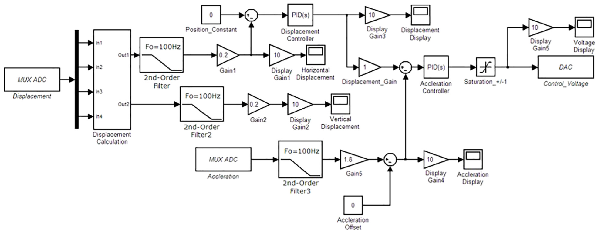
Cascade PID control system chart based on dSPACE.
The mixed H2/H∞ control system chart based on the dSPACE real-time control system is shown in Figure 14 and output feedback controller adopts the above-mentioned mixed H2/H∞ control model based on LMI method. When the PSD and accelerometer, respectively, input the displacement and acceleration signals of the experimental object to the output feedback controller within dSPACE, the control signal computed by the controller model is transferred to the power amplifier whose output control current could be utilized to control the position and acceleration of the actuator. In the process of simulation module design, the International Systems of Units (SI) are adopted for all physical quantities, and the collected acceleration and displacement signals are filtered by second-order filters, of which the cut-off frequency is set to 100 Hz.

H2/H∞ control system chart based on dSPACE.
During the experiment, the frequency and amplitude of the disturbance acceleration could be modulated by changing the voltage of vibration motor. The acceleration signal was collected to the dSPACE and the ControlDesk software was used to analyze the acceleration signal of the experimental object before and after the active control. The acceleration amplitude and frequency spectrum of the experimental object in the range of 1–15 Hz (frequency interval: about 1 Hz) were mainly measured. A total of 50 sets of experimental data corresponding to each vibration frequency were collected by changing the voltage of vibration motor. Afterward, the 50 sets of experimental data were processed in linear average. Table 5 lists the mean values of the self-power spectra of the 50 sets of acceleration signals before and after active control. Within the frequency range from 1 to 15 Hz, the cascade PID control effectively suppressed the acceleration vibration of the motor and attenuated the acceleration amplitude of control object by the range (1–10 dB), while the mixed H2/H∞ control attenuated the acceleration amplitude of control object by the range (3–12 dB). At each corresponding frequency, the mixed H2/H∞ control could attenuate at least about 1–2.5 dB more acceleration amplitude than cascade PID control. At 3.125 Hz, the mixed H2/H∞ control could attenuate almost 2.4 dB more acceleration amplitude than cascade PID control.
Attenuated vibration acceleration results.

PID: proportional–integral–derivative.
Due to the limited length, four groups of acceleration’s time domain data in different frequency (1.563, 5.938, 10.94, and 15 Hz; frequency interval: about 5 Hz) before and after active control are shown in Figure 15. The green line, blue line, and red line represent the uncontrolled acceleration, acceleration after cascade PID control, and acceleration after mixed H2/H∞ control, respectively. For the problem of single frequency vibration within the range of frequency (1–15 Hz), the acceleration amplitude is obviously attenuated by two kinds of control methods. Moreover, compared with the cascade PID control, the mixed H2/H∞ control attenuates the acceleration amplitude more obviously, which is a more effective vibration control method.

Comparison of the acceleration control effects.
Conclusion
In this article, the design and implementation of a mixed H2/H∞ output feedback controller based on the LMI method are presented. The particular problem selected treats a one-dimensional vibration isolation system and the kinetic model was established. To ensure the acceleration level of the experimental payload along with the constraints of actuator, the H∞ robustness index and H2 performance index were chosen from the model successively to build the state–space realization for the generalized plant. The MATLAB functions (hinfmix, normh2, and normhinf) were adopted, respectively, to compute the threshold values and true values of H∞ and H2 norms for the closed-loop system. The relationship between robust stability and nominal performance of mixed H2/H∞ control is specified by plotting the curves of threshold values and true values of H2 and H∞ norms. It indicates that the nominal performance of the system could be improved at the cost of its robust stability. The state–space realization of optimal controller with minimum H2 norm under the constraints of the H∞ norm is obtained and influence of structural parameters (M and K) uncertainty on the H2/H∞ indices was analyzed. It could be found that the changes of structural parameters mainly affect the performance index from the disturbance signal
In view of applying mixed H2/H∞ control to a 6-DOF microgravity vibration isolation platform, more work on the realization of active control for the maglev actuator would be carried out. We will try to calculate the size of conservativeness in the obtained controller model and reduce it. In order to make the model under consideration more realistic and general, the system would be with the feature of time-varying delay, actuator saturation, external disturbance, actuator fault, and input non-linearity.27,28 At the same time, the kinetic model is featured with obviously coupling characteristics as well as the uncertainty and non-linearity of structural parameters. Therefore, it is needed to indicate the change rule of structural parameters’ uncertainty and non-linearity characteristics, which reveals their influence on the coupling characteristics of the kinetic model. The optimized design of the mixed H2/H∞ controller model will be studied further, such as pole region constraints for the controller and weight gain in the input and output for the plant. Moreover, the techniques of fault estimation, fault diagnostic, or fault tolerant control would be applied in our research objects to improve system reliability.29,30
Footnotes
Acknowledgements
The authors would like to thank anonymous reviewers and handling editors for their useful comments and constructive suggestions, which do help improving the quality of this paper.
Handling Editor: Muhammad Akhtar
Declaration of conflicting interests
The author(s) declared no potential conflicts of interest with respect to the research, authorship, and/or publication of this article.
Funding
The author(s) disclosed receipt of the following financial support for the research, authorship, and/or publication of this article: This work was supported by the National Natural Science Foundation of China (nos 51205296 and 51275368).