
Abstract
In order to reduce the heat loss and improve the indicated thermal efficiency of hydrogen-enriched compressed natural gas engines, this article presents a combination of Atkinson cycle with high compression ratio and low heat rejection on the hydrogen-enriched compressed natural gas prototype engine with 55% hydrogen blend. The combustion characteristics and energy distribution of the prototype and modified engines were investigated by simulation, and the conclusions are as follows: the pressure and temperature of modified engines are higher than those of the prototype during the combustion process. Compared with the prototype, the modified engines present lower peak heat release rate, but faster combustion after ignition, and their CA50 are closer to top dead center. Although the high compression ratio engine with Atkinson cycle generates more heat loss, its indicated thermal efficiency still increases by 0.6% with the decrease in the exhaust energy. Furthermore, the high compression ratio engine with low heat rejection and Atkinson cycle combines the advantages of low heat loss and relatively longer expansion stroke, so its heat loss reduces obviously, and 61.6% of the saved energy from low heat rejection and Atkinson cycle can be converted into indicated work that indicates a 4.5% improvement in indicated thermal efficiency over the prototype, which makes it perform better in terms of power and fuel economy simultaneously.
Keywords
Introduction
In the current background of green, environmental protection, low carbon and sustainable development, energy saving and emission reduction are the urgent issues facing the automobile industry all over the world. In order to alleviate the crisis of oil resources shortage, various types of alternative fuels are applied to engines such as natural gas, hydrogen, biodiesel, and alcohol fuels. Natural gas is widely used due to its abundant reserves and low emission, but there are also some defects of slow flame propagation speed and high ignition energy. As for hydrogen fuel, it is not easy to be produced, although it is regarded as the ideal fuel; meanwhile, it is prone to preignition or backfire phenomenon in some conditions. 1 Hydrogen-enriched compressed natural gas (HCNG) can be obtained by adding a certain proportion of hydrogen (H2) into the compressed natural gas (CNG), which combines the advantages of CNG and H2, and can improve the combustion process of CNG engines as well as the thermal efficiency.
For exploring the comprehensive performance of HCNG engines, a great deal of research work has been done by scholars and research institutions around the world. In order to experiment accurately, Ma et al. 2 developed an online H2/CNG mixing system and analyzed the characteristics of mixture formation by spectroscopy. This system allows more convenient changes of hydrogen ratio during the test, and it is safer to mix H2 and CNG at low pressure. In addition, they established a two-zone quasi-dimensional ignition HCNG engine model for different hydrogen blending ratios based on fractal geometry and verified the application scope of this model under various working conditions in another article. 3 The results show that the adiabatic flame temperature and laminar burning velocity of the HCNG mixture have an important effect on the applicable range of hydrogen addition ratio. Many research works concluded that compression ratio (CR), hydrogen addition ratio, ignition advance angle, and equivalence ratio all have an important effect on HCNG engine performance.4–7 Gharehghani et al. 8 established a computational fluid dynamics (CFD) model of a HCNG engine coupled with a detailed chemical kinetic model. They found that CO, CO2, and HC production and combustion duration decrease with the increase in the hydrogen addition ratio, but the NOX is produced more under the condition of richer hydrogen, and they proposed that HC, NOX, and thermal efficiency should be considered synthetically when optimizing the mixture equivalence ratio. Tangöz et al. 9 studied the influence of hydrogen addition ratio, ignition advance angle, and engine speed on the performance of HCNG engines with high compression ratio (HCR). They found that, with the increase in the hydrogen addition ratio, the optimal ignition advance angle and the thermal efficiency decrease, which is consistent with the conclusions in the literature.10,11 Based on the experimental data, Orbaiz et al. 12 theoretically analyzed the performance of the ignited engine when it separately burned H2, CNG, and HCNG and explained why the propagation of the turbulent flame has a significant influence on these fuel engines. They also comparatively analyzed the energy balance of the engine burned these fuels in Orbaiz and Brear. 13 The results show that the heat loss of the CNG engine increases after blending hydrogen, but it decreases with the increase in the excess air ratio (λ), which is in line with the results in the literature.14–16 Furthermore, they concluded that the flame propagation of premixed combustion and the heat loss in the cylinder make a great difference on the performance of the HCNG engine. In addition, it has been proved that the cycle-to-cycle variations of CNG engines can be reduced after blending hydrogen17,18 and applying exhaust gas recirculation (EGR) technology on HCNG engines can reduce NOX emissions.19,20
Although the HCNG engine has many advantages, the mixture volume heat value is less when the hydrogen content is larger, and the heat loss increases on the condition that equivalent ratio is close to 1, resulting in a decrease in the thermal efficiency. Increasing the CR can improve the thermal efficiency; however, HCNG engines with HCR are prone to backfire. Compared with the conventional Otto cycle, which is close to the working process of the ignition engine, the Atkinson cycle makes the actual CR smaller than the expansion ratio through the variable valve timing technology, that is, even if the geometric CR is relatively large, the HCNG engine can be prevented from backfire by controlling the late intake valve closing angle (LIVC), and the relatively longer expansion process is conducive to improve the thermal efficiency. Besides, instead of throttle, Atkinson cycle adjusts the load by controlling LIVC, which reduces the throttle loss at part load. 21 Atkinson cycle is conducive to energy saving of engines, so its implementation methods, applications and challenges are widely concerned.22–24 Boggs et al. 25 achieved a flexible Otto-Atkinson cycle switching on a four-cylinder petrol engine with working on Otto cycle at full load and working on Atkinson cycle at part load, ultimately resulting in the improvement of fuel economy and emissions. Benajes et al. 26 greatly reduced the NOX emissions of the diesel engine after applying Atkinson cycle and EGR technology to the diesel engine. Toyota developed 3.5-L, six-cylinder V-type gasoline engines and 2.5-L, four-cylinder inline gasoline engines whose characteristics of power, fuel economy, and emissions are excellent by combining Atkinson cycle, high geometric CR, and a new generation of D-4S system. 27 Constensou and Collee 28 combined the variable CR technology and the variable valve train to achieve Atkinson cycle with high expansion ratio and validated its advantage of energy saving on a single cylinder engine.
Although the Atkinson cycle has been used in conventional engines and hybrid vehicles widely in recent years, less attention has been paid to applying the Atkinson cycle on HCNG engines. Theoretically, it can improve the thermal efficiency and effectively prevent the backfire at the same time if the HCNG engine with HCR works on Atkinson cycle. In addition, if the Atkinson cycle and low heat rejection (LHR) technology are combined on HCNG engines, heat loss would be reduced and more energy may be transformed to indicated work, thus the indicated thermal efficiency (ITE) of HCNG engines can be further improved. According to an experimental engine, a multi-dimensional CFD model and a one-dimensional simulation model of the HCNG engine with 55% H2 are established in this article and verified by the test data. And, the low heating value of 55% HCNG is 59,300 kJ kg−1. Then, these models of the prototype were modified to the models of the HCR engine with Atkinson cycle on the conditions of normal heat rejection and LHR to simulate and compare their combustion characteristic and energy distribution.
Technical scheme
Implementation of HCR
For improving the CR of the prototype from 10 to 12, a piston suitable for CR of 12 was designed based on the variable depth of the combustion chamber, which makes the depth of the combustion chamber reduce from 20 to 15.43 mm, as shown in Figure 1, that is, the volume of the combustion chamber decreases and the area–volume ratio increases when the piston is at the top dead center (TDC).

Cross section for combustion chambers.
Implementation of Atkinson cycle
As described in the previous chapter, the Atkinson cycle is realized by adjusting LIVC according to working conditions. For the actual valve train, the valve movement depends on the cam profile. In this study, VT-Design of GT-ISE software was used to design the suitable intake cam profile to match the working condition, which is based on the combined and higher polynomial method. The combination method is to divide the working segment of the cam into multiple areas, including buffer segment, acceleration segment, uniform velocity segment, deceleration section, and so on. The high-order polynomial is conducive to smooth the curves of the cam lift, velocity, and acceleration. However, when the polynomials order is too high, the plumpness coefficient of the cam profile and the stability of the valve mechanism are somewhat reduced. Hence, a combination of fifth-order polynomial is adopted in this research. To verify the rationality of the designed cam profile, the kinematics and dynamics of the valve train must be analyzed. Meanwhile, the design results will be analyzed in the section “Modified models.”
Implementation of LHR
The LHR engine can reduce heat loss of cylinders during the working process to improve ITE by spraying thermal insulation materials on the piston top, cylinder head, cylinder liner, and valves.29–32 In the simulation process, for the sake of achieving LHR condition in the cylinder, the heat convection of the combustion chamber components, including the piston top, cylinder head, liner, intake, and exhaust valves, was set at simulation software according to the thermal properties of Yttria-stabilized zirconia (YSZ), a thermal insulation material commonly used in LHR engines. The shaded areas of Figure 2 are the LHR regions, and the thermal properties of YSZ are displayed in Table 1.

LHR regions in the cylinder.
Thermal properties of YSZ.

YSZ: Yttria-stabilized zirconia.
Simulation model
The main specifications of the prototype engine used in this article are shown in Table 2. The multi-dimensional CFD model and one-dimensional simulation model of the prototype were established by AVL_Fire software and AVL_Boost software, respectively, which were verified and calibrated by test data. Then, the models were modified to the HCR engine models with Atkinson cycle under the conditions of normal heat rejection and LHR.
Main specifications of the prototype engine.
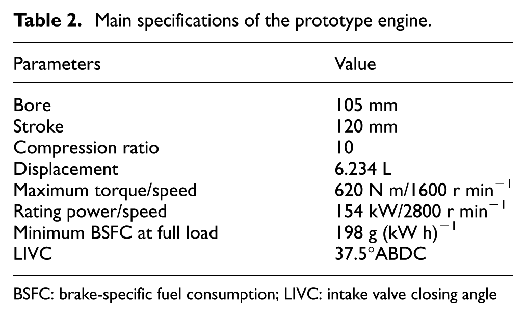
BSFC: brake-specific fuel consumption; LIVC: intake valve closing angle
Computational grid model
AVL_Fire is a CFD software which can accurately simulate the gas flow, spray, and combustion processes in the cylinder. According to the structural parameters of the prototype, the three-dimensional model, including the intake and exhaust ports, combustion chamber, valves as well as their valve seats when piston is at the TDC, was established by Pro/E software and converted into STL Mesh for the AVL_Fire. Based on the valve lift of the prototype, the dynamic computational grids of the HCNG engine were built by the automatic grid generation tool called FEP (fame engine plus). The simulation calculation cycle includes a whole working cycle of the cylinder, from 360°CA to 1080°CA, and the total number of grids at the beginning of the intake stroke (360°CA) is 672,083 cells, which can be shown in Figure 3.

Computational grids.
According to the structure parameters and the established CFD model of the prototype, a one-dimensional model of the prototype was established by AVL_Boost software. In order to simplify this model, the turbocharger and intercooler were omitted; instead, the temperature and the pressure of the measurement point in the bench test were directly used as the boundary conditions of the model. The final model shown in Figure 4 contains six cylinders, an injector, pipes, restrictor valves, and so on. The one-dimensional model is to calculate the performance of the engine more accurately by coupling the CFD results including the pressure, temperature, and other conditions in the cylinder.

One-dimensional simulation model.
Numerical model
Turbulence model
The standard k-ε model is commonly used to solve the turbulent kinetic energy (k) and its dissipation rate equations (ε) in the engines simulation process. 33 The model assumes that the flow is completely turbulent and the effect of molecular viscosity can be ignored. This study also used the two-eq1 standard k-ε model to simulate the turbulence in the cylinder

where σk = 1, σε = 1.3, Cε1 = 1.44, and Cε2 = 1.92.
Combustion model
The coherent flame model (CFM) model 34 is suitable for premixed and non-premixed combustion based on laminar flame. In premixed combustion, the average velocity and thickness of the flame front are determined by the pressure, temperature, and mixture concentration. This model takes into account the interaction between chemical reactions and turbulence, assuming that the flame front is a thin surface that separates the unburned gas from the combustion products. The model analyzes the combustion process of the mixture in the cylinder by solving evolution equation of flame surface density, which can be expressed as follows
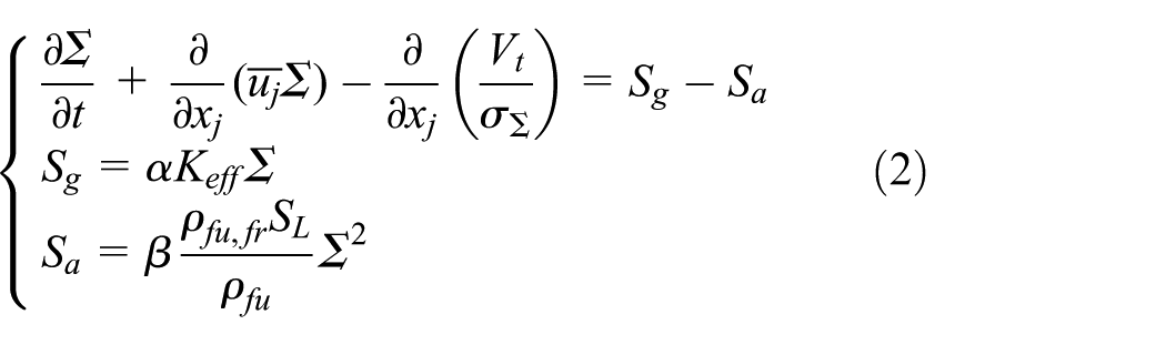
where Σ is the flame surface density, SL is the propagation velocity of laminar flame, xj stands for the distance, σ∑ is the turbulent Schmidt constant, Vt is the turbulent kinematic viscosity, Sg is the product of the turbulence change rate on the flame surface, Sa is annihilation of the flame surface caused by fuel consumption, Keff is the average diffusion rate of flame, α and β are adjustable factors, ρfu refers to the density of fuel, and ρfu,fr is the density of the mixture.
The propagation velocity of laminar flame is determined by the local pressure P, temperature Tfr and unburned mixture concentration, as shown by the following formula

where
The average turbulent reaction rate is calculated from the flame surface density Σ and the propagation velocity of laminar flame SL, as shown in following formula

where ρfr is the density of fresh air, and yfu,fr refers to the mass fraction of fuel.
The prototype is an intake port fuel injection and ignited HCNG engine. Therefore, CFM model is selected as the flame propagation model in the CFD model. So as to ensure the consistency of the CFD model and the one-dimensional model during the simulation, the combustion model of the one-dimensional model is obtained by coupling with the heat release rate calculated by the CFD model.
Heat transfer model
Owing to the relatively high Reynolds number, the k-ε two-equation turbulence model used to simulate the flow in the intake pipe is not suitable for the near-wall region. Besides, molecular viscous damping and velocity fluctuations perpendicular to the wall affect the flow and heat transfer near the wall. Therefore, the near-wall gas flow and heat transfer are simulated by a unique model that takes into account the molecular viscous effect and turbulent kinetic energy of the near-wall. 35 The thermal conductivity of the near-wall in this model is obtained from the following formulas

where λ represents the thermal conductivity of the boundary layer, yp denotes the distance from the node P of the near-wall to the boundary, yT stands for the thickness of the thermal boundary layer, Up is the velocity of the node P, and Y represents the viscous damping factor.
The thermal boundary conditions of walls can be defined by a variety of methods. The AVL_fire software can calculate not only the heat loss based on the fixed boundary temperature set according to the experimental data but also the wall heat loss and variable temperature according to the heat convection conditions when the thermal physical properties of materials are input. In addition, the external heat loss is determined by the external wall temperature, environment temperature and the external heat convection coefficient. All of these can be described in the following formulas

where Db represents the heat loss of the boundary, hi stands for the heat convection coefficient between the cylinder gas and the wall, Tb is the boundary temperature,
Boundary conditions
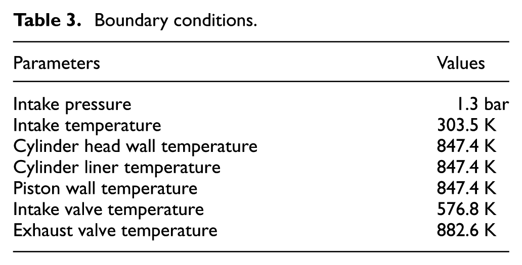
The initial boundary conditions of the prototype include the intake conditions and the temperature boundary conditions. The parameters in the simulation model are set according to the test data under the same working conditions. The main boundary conditions are shown in Table 3.
Boundary conditions.
Experimental validation
In order to validate the reliability of the simulation model and methods, an experiment was performed on the prototype under the appropriate working conditions, which can refer to the previous study,5,36 and the experimental conditions are shown in Table 4. The prototype is a turbocharged natural gas engine with six inline cylinders, and its main technical parameters have been shown in Table 2. The electronic control system of the engine adopts the ITMS-6F electronic control unit produced by Delphi Corporation (Troy, Michigan, USA). In addition, the main instruments used in the experiment include CW260-1800/7500 eddy current dynamometer, 6117B spark plug pressure sensor, DL750 ScopeCorder signal acquisition, Coriolis mass flow meter, 20N100114LI thermal gas mass flow meter, and so on.
Experimental conditions.

HCNG: hydrogen-enriched compressed natural gas.
Under the experimental conditions, the in-cylinder gas pressures obtained from the CFD model and one-dimensional model were in good agreement with the experimental result, which is shown in Figure 5. The peak pressure calculated by the one-dimensional and CFD models are 7.39 and 7.29 MPa, whose errors are 0.8% and 0.5%, respectively, compared with test data. Furthermore, the performance parameters calculated by the one-dimensional model and the corresponding experimental data are shown in Table 5. It is obvious that the simulation models are credible and can be used for the research because of the smaller error.

Experimental validation.
Validation of performance parameters.

Results and discussion
Modified models
In order to investigate the performance of the HCR engine with the Atkinson cycle under the conditions of normal heat rejection and LHR, the prototype model was modified as follows.
First, the CR of the prototype was improved from 10 to 12, just as described in section “Implementation of HCR.” Second, a suitable intake valve lift curve was designed to make the HCR engine operate on Atkinson cycle. The design method has been described in section “Implementation of Atkinson cycle,” and two principles should be followed when designing the valve lift curve: (1) ensure valve train work reliably, such as better motion, smaller valve seating velocity and smaller impact force. (2) Prevent the backfire phenomenon in HCNG engines with HCR by maintaining the same effective CR as the prototype when designing intake valve lift for the HCR engine, that is, the actual CRs of the two are consistent when the intake valve is closed. The comparison between the improved intake valve lift and the original lift is shown in Figure 6. The important parameters of the valve train are listed in Table 6. And, Figure 7 shows the temperature of the cylinder, intake port, and exhaust port at the late stage of exhaust stroke. It can be seen from the above figures and table that the optimized LIVC is 72°ABDC, the valve lift curve is smooth, and the valve train works reliably without backfire. The method of LHR is described in section “Implementation of LHR,” which is to set the convective conditions on the top of piston, cylinder head, cylinder liner, and valves of the simulation model according to the thermal physical properties of YSZ.

Comparison of intake valve lifts.
Parameters of the valve train.


Temperature of intake stroke around the TDC.
Under the different working cycles and heat rejection conditions, the prototype model and the modified model have different performances, including intake flow, combustion, and ITE. Based on the simulation results, the combustion characteristics and energy distribution of the HCNG engine were analyzed under the conditions of original with Otto cycle (CR10), HCR with Atkinson cycle (CR12 + Atkinson), and HCR with Atkinson cycle and LHR (CR12 + Atkinson + LHR) when the engine worked under the condition of 1200 r min−1, full load, and λ of 1.3.
Combustion characteristic
The combustion mode of the prototype belongs to premixed combustion. After the spark ignition, the temperature of local mixture rises sharply, then the flame nuclei forms and propagates as a frame front. Figure 8 and 9 show the in-cylinder gas pressure and temperature of the engine under three conditions, respectively. It can be seen from the figures that the pressure is basically the same before combustion under the three conditions, however, the pressure of the CR10 engine is much lower than that of the CR12 + Atkinson engine at the combustion stage, and the CR10 engine attains the maximum pressure later than that of the CR12 + Atkinson engine. Furthermore, the peak pressure of CR12 + Atkinson + LHR engine is further improved because of low heat loss, and its corresponding phase is ahead of time. The peak pressures under the conditions of CR10, CR12 + Atkinson, and CR12 + Atkinson + LHR are 7.29, 8.12, and 8.45 MPa, respectively. Besides, the pressure of the CR12 engine decreases faster than that of the CR10 engine after the end of combustion. Compared with the in-cylinder gas temperature of the CR10 engine, the temperature of the CR12 + Atkinson engine rises faster after the start of combustion, and its maximum is equivalent to that of the CR10 engine. However, the temperature of the CR12 + Atkinson engine drops more rapidly than that of the CR10 engine after the combustion. Owing to the less heat loss, the temperature of the CR12 + Atkinson + LHR engine not only further grows faster, and its peak value is also higher than that of the CR10 engine; besides, it maintains the equivalent level to that of the CR10 engine at the expansion stroke after combustion.

Comparison of pressure.

Comparison of temperature.
The different trends of in-cylinder gas pressure and temperature of the HCNG engine under the three different conditions can be reflected by their different combustion and heat release rates. Figure 10 shows the instantaneous heat release rates of the HCNG engine under the three conditions described above. As can be seen from Figure 10, the peak heat release rate of the CR10 engine is maximum among the three because of the smaller LIVC. Compared with the CR10 engine, the intake valve of modified engines closes later so that more mixture in the cylinder is pushed back to the intake manifold by the upward piston, which causes to the final air inflow of modified engines with Atkinson cycle is less than that of the CR10 engine, so the peak value of heat release rate is relatively small. However, the CR12 + Atkinson engine burns faster than the CR10 engine after ignition, whose heat release rate reaches the maximum earlier. Due to the less heat loss, higher pressure, and temperature, the CR12 + Atkinson + LHR engine further accelerates its combustion, reaching the peak value of heat release rate around the TDC, and it is noteworthy that its maximum heat release rate is higher than that of the CR12 + Atkinson engine, but still lower than that of the CR10 engine. However, after reaching the maximum heat release rate, the heat release rates of the modified engines decrease rapidly and are lower than that of the CR10 engine at the same time until all of them reach the same level at the late stage of combustion. In order to further analyze the combustion characteristics of the engine under the three conditions in detail, the phases of the cumulative heat release rates of 10%, 50%, and 90% (CA10, CA50, and CA90) are analyzed below. The CA10, CA50, CA90, and CA10–CA90 duration of the HCNG engine under the three conditions are shown in Table 7.

Comparison of heat release rate.
Significant phases in combustion process.

LHR: low heat rejection.
CA10–CA90 is often used to characterize the duration of apparent combustion period, that is, CA10 and CA90 indicate the phase at the beginning and end of apparent combustion period, respectively. Compared to the CR10 engine, the CR12 + Atkinson engine achieves CA10 and CA50 sooner after ignition, and it would achieve CA10 and CA50 earlier after decreasing the heat loss, which further illustrates that the CR12 + Atkinson + LHR engine burns and releases heat faster after ignition. But the difference of CA90 under the three conditions is not obvious, so the modified engines have a longer apparent combustion period than the prototype. Although the heat release rate of the modified engines is faster before reaching CA50, it drops rapidly due to the decrease in the flammable mixture after CA50, while the heat release rate of the CR10 engine is still relatively high. Besides, it can be found from Figure 9, there is no obvious difference in the heat release rate of the HCNG engine under the three conditions in the late stage of combustion, especially after 10°ATDC. Because most of the mixture has been burned at this moment, and only a little residual mixture continues to combust and release heat. Hence, the HCNG engine has the similar CA90 under the three conditions. Nevertheless, the pressure and temperature of the CR12 + Atkinson + LHR engine are still higher than other two situations in this stage, so it reaches CA90 slightly earlier.
Energy distribution
The fuel energy of the ignition engine is mainly converted into the indicated work, heat loss, and exhaust energy. As mentioned in section “Introduction,” the heat loss increases when the HCNG engine works under the theoretical equivalence ratio. By combining the LHR technology and the strategy of HCR with Atkinson cycle, the heat loss of HCNG engines can be reduced, especially the heat loss of the combustion chamber wall during the combustion process; besides, the expansion stroke is relatively longer than effective compression stroke, so more energy can be converted to indicated work for improving ITE. Under the three conditions, the different characteristics of combustion and heat release have an important impact on the work and heat convection, which further affects the energy distribution of the engine. The energy distribution characteristics of the prototype and the modified engines are discussed as following.
Figure 11 shows the wall heat flux of combustion chamber when the HCNG engine works on the three conditions, including the top of piston, cylinder head, liner, intake valve, and exhaust valve. It can be seen from Figure 11 that the heat flux of the engine under the three conditions is large during the combustion process because the higher in-cylinder gas temperature leads to a larger temperature difference between the combustion chamber wall and in-cylinder gas at this stage. Therefore, the heat convection between the in-cylinder gas and the wall is strong. Compared with the CR10 engine, the heat flux of the CR12 + Atkinson engine around the TDC is higher, while it is slightly lower than that of the CR10 engine after combustion. The main reason is that the CR12 + Atkinson engine has higher in-cylinder gas temperature near the TDC than the CR10 engine, and its area–volume ratio of combustion chamber is relatively large, which would result in more heat loss. But its temperature declines faster after combustion, that is, the temperature difference between in-cylinder gas and wall is slightly lower than that of CR10 engine, so its heat flux is slightly lower than the CR10 engine after combustion. However, it is apparent that the wall heat flux of the CR12 + Atkinson + LHR engine reduces significantly during the combustion and expansion process. Under the condition of LHR, the wall temperature of combustion chamber changes with the variable in-cylinder gas temperature obviously, which leads to the small temperature difference between the in-cylinder gas and wall, thus the strength of heat convection is weaker than that of normal cooling condition. Therefore, less heat loss appears on the CR12 + Atkinson + LHR engine.

Wall heat flux in CFD model.
In order to further analyze the fuel energy distribution, the one-dimensional model, coupled with the heat release rate and the heat rejection conditions obtained by the CFD model, was used to simulate the engine performance under the same working condition. Figure 12 shows the wall heatflow of a cylinder at compression and expansion strokes in the one-dimensional model operated under the three conditions, whose heat loss law is consistent with the heat flux obtained in the three-dimensional model.

Wall heatflow in one-dimensional model.
The energy distribution of the engine under the three conditions are shown in Figure 13; compared with the CR10 engine, the ITE of the CR12 + Atkinson engine only increases by 0.6% although the exhaust energy decreases because of the longer expansion stroke. On one hand, the CR12 + Atkinson engine has the same effective CR with the CR10 engine, and its throttling loss and pump loss are equivalent to those of the CR10 engine because of the full throttle at the full load. On the other hand, its combustion chamber has larger area–volume ratio than that of the CR10 engine, making its heat loss increase. However, the heat loss of the CR12 + Atkinson + LHR engine reduces significantly. Although a part of energy saved by LHR and Atkinson cycle is still taken off by the exhaust gas, the modified engine has a longer expansion stroke, so 61.6% of the saved energy could be converted into the indicated work that indicates a 4.5% improvement in ITE over the prototype. Another reason for the improved ITE is the earlier CA50 of the CR12 + Atkinson + LHR engine, enhancing the level of isochoric heat release around the TDC.

Comparison of energy distribution.
The performance of the engine is closely related to its combustion characteristics and energy distribution, and Table 8 shows the performance parameters of the prototype and modified engines. Compared with the CR10 engine, the brake torque (Ttq) and the brake power (Pe) of the CR12 + Atkinson engine are lower because of the decreased volumetric efficiency after delaying the IVC. However, because 61.6% of the saved energy from LHR and Atkinson cycle can be converted into the indicated work, the power output of the CR12 + Atkinson + LHR engine improves apparently, even is better than that of the CR10 engine. Besides, the modified engines exert lower brake-specific fuel consumption (be) than the CR10 engine, which is in line with their indicated work.
Performance parameters for three engines.

LHR: low heat rejection.
Conclusion
To investigate the combustion characteristics and energy distribution of the HCNG engine with LHR based on Atkinson cycle, this article developed and validated the CFD model and one-dimensional simulation model based on the experimental data of the prototype. Meanwhile, the models were modified to realize the LHR and Atkinson cycle with HCR. By simulating and comparing the combustion and energy distribution of the prototype and modified engines under the condition of 1200 r min−1 and full load, the conclusions are as follows:
Compared with the CR10 engine, the in-cylinder gas pressure and temperature of the CR12 + Atkinson engine are higher during the combustion process, but drop to a lower level after combustion. Furthermore, the CR12 + Atkinson + LHR engine has higher pressure and temperature than the CR12 + Atkinson engine because of the less heat loss, and its pressure and temperature after combustion are equivalent to those of the CR10 engine. Besides, not only the peak pressure and temperature of the CR12 + Atkinson + LHR engine are higher than those of other situations, the corresponding phases are also advancing.
Although the peak heat release rate of the CR10 engine is higher than that of the CR12 + Atkinson engine and CR12 + Atkinson + LHR engine, the modified engines have a faster combustion rate than the prototype after ignition, with the earlier CA10 and CA50. However, there is no obvious difference in CA90 of all, thus the CA10–CA90 duration of the prototype is shorter. After reaching the peak value, the heat release rates of modified engines are lower than that of the prototype until all of them maintain an equivalent level at the end of combustion.
The CR12 + Atkinson engine induces more heat loss than the CR10 engine, but its ITE still increases by 0.6% than the CR10 engine because of the less exhaust energy. The CR12 + Atkinson + LHR engine combines the advantages of LHR and relatively longer expansion stroke, so its heat loss only accounts for 11% of the total energy and the ITE could attain 44.1% though lots of energy is taken off by the exhaust gas. It is worth mentioning that 61.6% of the saved energy from LHR and Atkinson cycle could be converted into indicated work.
The CR12 + Atkinson engine indicates lower power output and fuel consumption compared with the CR10 engine, but the CR12 + Atkinson + LHR engine shows better power and fuel economy than the CR10 engine simultaneously.
Footnotes
Handling Editor: Mohammad Reza Salimpour
Declaration of conflicting interests
The author(s) declared no potential conflicts of interest with respect to the research, authorship, and/or publication of this article.
Funding
The author(s) disclosed receipt of the following financial support for the research, authorship, and/or publication of this article: This research was sponsored by the Chongqing Graduate Education Innovation Fund Project (grant number: CYS17198) and the Chongqing Key Technology Innovation Project of Key Industries (grant number: cstc2015zdcy-ztzx60014).