
Abstract
In order to solve the problem that the photoelectric instrument may fail when the vibration response of the truss composite structure is too large, the method of applying the viscoelastic-constrained damping layer on the truss wall and the box panel is used to reduce the vibration of the whole structure. In this article, a broken long tube with viscoelastic-constrained damping layer is introduced. The long tube of the original structure is broken into two identical short tubes, and a tube with free damping layer is added to the junction of the two short pipes, which is connected by adhesive and broken long pipe. By analyzing the frequency response of the traditional space truss and spaceflight load structure, and a broken long tube structure, the acceleration response cloud diagram and the acceleration response curve of the fixed measuring node are obtained. Experiments were carried out to verify the feasibility of the structure. The test results show that the method of broken long pipe with viscoelastic-constrained damping layer can achieve better damping effect than the traditional truss structure, and it can effectively reduce the vibration level of the space load at the end of the truss, and has important reference significant for the vibration reduction design of other space structures.
Introduction
With the development of spacecraft toward the direction of large scale and complexity, the space truss has been applied more and more widely because of its easy disassembly, good technology, light weight, and the ability to adjust the structure according to the specific needs. It is also an important part of the International Space Station as shown in Figure 1. The space truss is mainly used in two aspects. One is to connect the related optoelectronic equipment at the top of the space truss to separate the electronic equipment so as to reduce the interference between each other. The other is as a supporting structure to support large deployable antennas in space and solar panels on satellites.

Space station truss structure.
The space truss and its load are launched through the launch vehicle. The vibration environment experienced by the launch vehicle is mainly divided into random vibration environment and low-frequency sinusoidal vibration environment. 1 Random vibration is mainly caused by engine exhaust noise during take-off, aerodynamic noise in transonic flight section, and pressure pulsation in the combustion chamber of the engine. The low-frequency sinusoidal vibration is mainly caused by the pogo vibration, engine start, flameout, and interstage separation of the projectile structure; the low-order modal free oscillation is caused by the gust and the shock wave oscillation in the transonic flight segment; and low-order longitudinal oscillation is caused by incomplete combustion of the engine. This kind of low-frequency vibration environment will cause the space truss structure to be damaged, the connection will be loose, the structural parts will be deformed, and the performance will be decreased. At the same time, this vibration will cause the precision of the photoelectric instruments to be reduced, mechanical fatigue, short circuit, and open circuit instantly, as well as functional failure. 2 Therefore, it is necessary to study the vibration characteristics and vibration suppression of space truss and its load. 3 There are many literatures on the vibration reduction of space truss structures, which are mainly divided into two categories: damper and damping layer. In previous works,4–6 dampers were designed according to the structure of the space truss, and the relationship between the placement position of the damper and the damping control effect was studied. YM Park et al. 7 proposed a semi-active control method using dry friction dampers to reduce the transient vibration of the space truss structure. J Yang et al. studied the vibration and damping properties of a hybrid carbon fiber composite pyramidal truss sandwich panel embedded in a viscoelastic layer in a panel. The damping effect of the damping layer is analyzed by simulation and experiment. 8 Based on the modal strain energy (MSE) method, C Liu analyzed the vibration fundamental frequency, loss factor, and resonance response peak of the composite truss structure with different damping layers. The influence of structural parameters and material parameters of damping layer on the damping effect of composite truss was studied. 9 In the traditional space truss, the damping layer is directly applied to the long pipe, 10 and the damping effect is not good due to the long pipe and the large stiffness. In this article, the traditional truss structure is improved, with a free damping layer on the connection of multi-section short pipe, and the growth tube is connected by adhesive and short pipe. The viscoelastic damping layer is applied to the space truss and space load structure for vibration reduction according to actual needs. Through simulation and experimental comparison, the new composite structure is lighter in weight, less rigid, and better in damping effect. Such a complete system of mutual verification of simulation tests has a positive guiding significance for the application of viscoelastic damping layer in aerospace field.
Basic theory of viscoelastic damping materials
When elastic material is subjected to external force,
11
the stress and strain increase or decrease at the same time, the phase of the two is basically the same, and the stress–strain relationship is a straight line. The viscoelastic damping material is different from the elastic material,
12
after the external force is applied. The strain lags behind the stress, and the hysteresis phase angle is
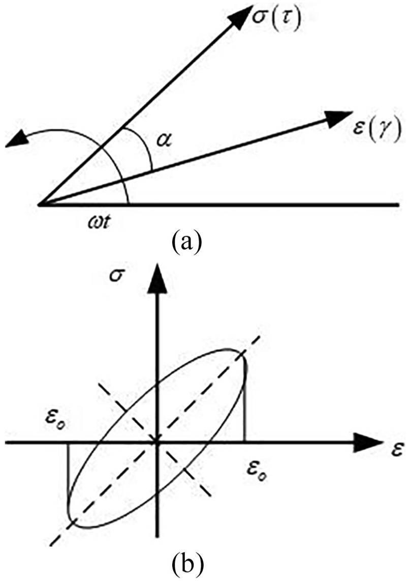
Stress–strain relationship of viscoelastic materials: (a) strain lags behind stress and (b) stress–strain curve.
The figure area surrounded by the elliptic curve in Figure 2(b) shows the vibration energy consumed by the viscoelastic material after the vibration of the structure. When viscoelastic materials are subjected to external loads to produce elastic deformation, the mathematical expression of stress–strain relationship is as follows 14


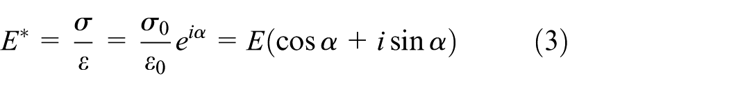
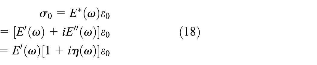
In this article, the complex mode method is used to describe the properties of viscoelastic damping materials, 15 according to the definition of complex modulus (tensile modulus)

If the viscoelastic damping material is subjected to shear deformation, the mathematical expression of the shear stress–strain relationship is as follows 17


The complex shear modulus is


Among them,
In the practical application of viscoelastic damping materials, it is necessary to decide when to adopt shear modulus, when to adopt tensile modulus, and when to use the relation between shear modulus and tensile modulus according to the specific stress condition. 18 The mathematical expression of the relationship between shear modulus and tensile modulus is as follows

Among them,
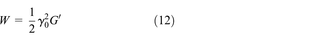
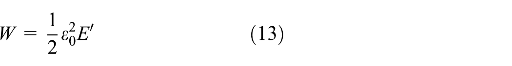
The energy consumption of viscoelastic damping materials per unit volume during a vibration period under the action of alternating stress and strain can be expressed in terms of


Where the maximum elastic energy, that is, the total strain energy W within a period
Therefore, the ratio of energy consumption to storage energy 20 is


Formula (15) shows that the damping factor
The magnitude of damping factor represents the level of damping, 21 which reflects the vibration reduction effect of the structure.
1. MSE method
The damping factor can be easily obtained by the MSE method in the finite element software MSC/NASTRAN. 22
The damping factor of r-order mode can be expressed as
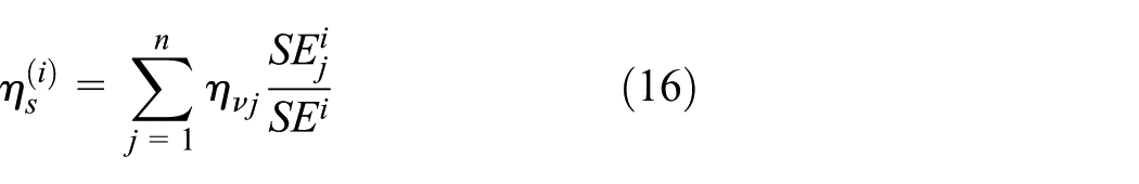
where
It can be seen from formula (16) that the damping factor is calculated by the ratio of the viscoelastic damping layer to the energy consumption of the whole structure by the MSE method. The disadvantage of the MSE method is that it is not accurate to assume that the properties of viscoelastic materials do not change with frequency, and the frequency variation of viscoelastic damping materials is not taken into account. In order to solve this problem, the modal damping factor can be simply modified according to the following formula (23)

where
2. Complex eigenvalue method (CEM)
Using the complex modulus model, the constitutive relations of viscoelastic materials are as follows 23

where
The free vibration equation of viscoelastic damping composite structure is as follows:


where M is the mass matrix,
When

Where

Thus, the n-order modal damping factor

where
The advantage of CEM is that it can describe the dynamic mechanical properties of viscoelastic damping materials. 24 The drawback is that it is necessary to calculate in the complex domain. The eigenvalue and eigenvector are usually complex, which results in a very large amount of computation, which is 5 ~ 10 times of the undamped characteristic solution.
The frequency and damping of viscoelastic damping composite structures are calculated by using COMPLEX EIGENVALUE (SOL 107) module in NASTRAN. 25 The concrete method is to establish the finite element model of viscoelastic damping composite structure, and then input the material damping and related material properties of viscoelastic material. In this article, the damping factor is calculated by the CEM. The uncoated viscoelastic damping layer structure is assumed to be undamped structure, and the damping factor is calculated to be an increment of the damping factor.
Design of truss and load structure
For space truss structure modeling and space load, as shown in Figures 3 and 4, the whole structure is made up of long tube, before and after the short tube, cover up and down, left and right sides cover plate, plate, connecting block many parts, fixtures and fittings, standard screw, weighs 15.848 kg, and the material for AL7075.

Three-dimensional model.

The connection of connecting block.
The structure of the space load box is made of a plate-like structure, with a hollow structure inside, and a screw is used to connect the various surfaces. In addition to the eight faces of the structure of the box structure, the center of the other surfaces has a circular groove with a diameter of 18 mm and a depth of 2 mm. It is used for connecting pieces, connecting the long pipe, short pipe, and connecting block through the connecting piece.
The establishment of finite element model
The finite element model adopts the right-hand coordinate system: the origin o is located at the center line of the lower cover plate along the space load length direction, the left cover plate points to the right cover plate and the y axis along the space load width direction, and the front cover plate points to the back cover plate in the positive direction of z axis.
By choosing the international system of units, the mesh is divided by the whole automatic part manually, the mesh elements are triangular and quadrilateral elements, and the connecting blocks and connectors are partitioned by volume mesh, as shown in Figure 5.
Connection box and connector.
The other parts are divided into shell meshes, and the finite element model is shown in Figure 6. The number of units is 338,564, the number of nodes is 162,717, and the weight of the model is 15.23 kg.

Finite element model of the original space truss and aerospace load structure.
A broken long tube structure is introduced. As shown in Figure 7, the long tube of the original structure is broken into two identical short tubes, and a AL7075 tube with a length of 50 mm, an outer diameter of 12 mm, and a wall thickness of 2 mm is added at the junction of the two short tubes. A free damping layer with thickness of 2.5 mm is applied to it, which is connected by adhesive and broken long pipe.

New structure of long tube broken.
Because the space load box structure is axisymmetric structure, in order to facilitate the study, the upper cover plate, the middle position of the left cover plate and the front cover plate, and the middle position of each long pipe are added with the constrained damping layer in the upper cover plate of the space load box structure, the middle position of the left cover plate, and the front cover plate.
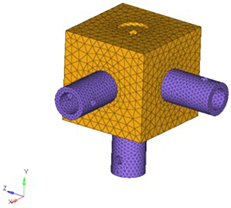
The damping layer uses a volumetric grid, and the constraint layer uses a shell grid with a bias. The elements share nodes, as shown in Figure 8.

Constrained damping layer.
The new finite element model of breaking long tube is shown in Figure 9. The number of units is 386,743, the number of nodes is 193,026, and the new structural model is 16.20 kg.

The finite element model of the new structure of break long tube.
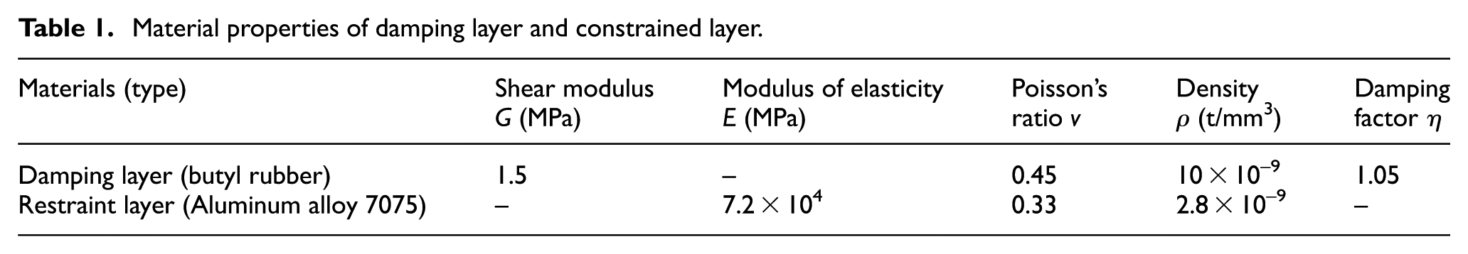
The damping layer is made from Beijing Institute of Aerospace Materials (703). The thickness of damping layer is 0.8 mm, the material is rubber, and the restraint layer is AL7075 plate with thickness of 2 mm. The material properties of the damping layer and the restraint layer are shown in Table 1.
Material properties of damping layer and constrained layer.
The modal test
The modal test of truss and load structure is carried out, and the truss structure is fixed to the vibration table. The constraint boundary of the simulated truss structure is shown in Figure 10. The test node layout is shown in Figure 11, with a total of 38 measurement nodes, and the excitation method is used to stimulate. The minimum elastic frequency of the clamping device used for support is much higher than the maximum analysis frequency of the specimen structure. Generally speaking, it is easy to realize the constraint boundary of small and medium structures, but it is difficult to realize the constraint boundary of large structures. 26 The quality of the truss structure in this article is 15.85 kg, the analysis frequency is 200 Hz, the vibration table is 4500 kg, and the first-order resonant frequency is 2200 Hz, which satisfies the requirements of the truss structure constraint boundary.

Modal test.

Geometric model.
The modal test analysis bandwidth of truss structure is 200 Hz, the frequency resolution is 1 Hz, and the steady-state diagram of the frequency response function (FRF) is shown in Figure 12.

Steady state diagram of frequency response function.
Modal correlation analysis
In this article, modal confidence criterion (MAC) in formula (2) is used as quantitative evaluation index

In the formula,
In this article, LMS Virtual Lab software is used to conduct correlation analysis based on the results of finite element modal analysis of truss and load structure and modal experimental results. As shown in Table 2, the finite element modal is similar to the experimental mode, and the first two order MAC values are all around 0.9, and the finite element model is acceptable.
Modal MAC values and frequency differences of modes.

Frequency response analysis of space truss and space load structure
According to the sinusoidal frequency sweep mode of the acceptance stage, the sinusoidal response of the space truss and the spaceflight load structure is analyzed in three directions, and the integral acceleration response cloud diagram is obtained. In order to quantitatively determine the magnitude of acceleration response at a certain position on the space load structure, in this article, the nodes of the front cover, the left cover, and the upper cover of the space truss and the space load structure are selected for analysis, and the acceleration response curves of the fixed measuring nodes are generated. The locations and numbers of the test nodes are shown in Figure 13.

Measuring node position of three-dimensional model.
In the finite element model, the corresponding number of measuring nodes 1–4 in three-dimensional (3D) model is 19,545; 27,222; 4912; and 254,679.
The last test node 4 is the basic excitation node. The location of these nodes corresponds to the location of the sensor in the subsequent test, and the location of the measured nodes in the finite element model is shown in Figure 14.

Measuring node position of finite element model.
The purpose of this analysis is to determine the acceleration response amplification of the existing space truss and space load structure under the condition of the acceptance stage sinusoidal sweep frequency, on the contrary, to compare the acceleration response data with the structure with viscoelastic damping layer.
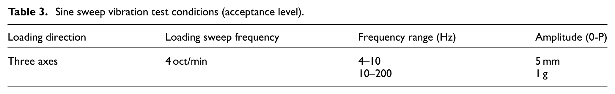
The sinusoidal response of the space truss and the spaceflight load structure is analyzed in three directions according to the sinusoidal frequency sweep mode of the acceptance stage and the specific test conditions as shown in Table 3. Take node 1 as an example to output the acceleration response curve as shown in Figure 15.
Sine sweep vibration test conditions (acceptance level).

Node 1 acceleration response curve: (a) X direction, (b) Y direction, and (c) Z direction.
By looking at the acceleration response curves of the measured nodes in the 0–200 Hz range, the maximum response frequency of the original structure in the X direction is 22 Hz. The maximum response frequency in the Y direction is 117 Hz. The acceleration response of the whole space truss and space load structure is shown in the corresponding maximum frequency in each direction as shown in Figure 16.

Acceleration response of space truss and space load structure: (a) X direction, (b) Y direction, and (c) Z direction.
By looking at the acceleration response curves of the measured nodes in the 0–200 Hz range, the maximum response frequency of the new structure in the X direction is 19 Hz. The maximum response frequency in the Y direction is 17 Hz. The maximum response frequency in Z direction is 99 Hz. The acceleration response of the whole space truss and space load structure is shown in each direction at the corresponding maximum frequency, as shown in Figure 17.

Cloud diagram of acceleration response of a new long tubular structure: (a) X direction, (b) Y direction, and (c) Z direction.
The comparison of acceleration response values at measuring node 1 for the original structure and the broken long tube new structure is shown in Table 4.
Comparison of acceleration response in simulation analysis.

Vibration test of space truss
Vibration test is a test to evaluate the vibration resistance of a single component or a whole machine structure in a predetermined transportation and service environment. 27 The main parameters of vibration test are amplitude, velocity, and acceleration. There are two common modes of vibration: one is sinusoidal vibration and the other is random vibration. Sinusoidal vibration test is often used in the laboratory. It is the vibration test of the structure under the action of sinusoidal excitation. The sinusoidal vibration can be divided into sweep vibration and constant frequency vibration. Random vibration test is an experiment of structure under random excitation. Random vibration is a kind of unstable vibration, which can be divided into stationary and non-stationary random vibration. 28
The experimental objects are the original space truss and spaceflight load structure and the new structure of breaking long pipe, in which the new structure of breaking long tube needs to be coated with constrained damping layer on the space load box structure, as shown in Figures 18 and 19. The free damping layer is added to the connecting pipe. The long pipe is connected by adhesive to the long tube, which is connected by screws to the connecting box through the connector, as shown in Figure 20.

The damping layer and the constrained layer.

Paste process of damping layer and constrained layer.

The composite structure of long tube damping.
The purpose of the test is to obtain the acceleration response of the original space truss and spaceflight load structure and the new structure with broken long tube in three directions by vibration test. The results are compared with the simulation results. To evaluate the damping effect of the two structures, the photos taken during the experiment are shown in Figure 21.

Vibration test field photo.
The test equipment includes electromagnetic shaking table (Space Hill 10t Station, Model H1248a), power amplifier, vibration controller, data acquisition instrument, computer, acceleration sensor, and vibration test equipment as shown in Figure 22.

Vibration test equipment.
The specifications, models, and functional parameters of the main instruments used in the whole vibration test process are shown in Table 5 below.
Specifications, models, and technical parameters of the sensors.

The flow chart for vibration testing and analysis is shown in Figure 23.

Flow chart of vibration test.
FRF analysis mainly obtains the relation between input and output position through the transfer function. FRF is the ratio of the Fourier transform of the response to the Fourier transform of the force or the ratio of the cross-spectrum of the force and response to the self-spectrum of the force. The FRF can be obtained by a dedicated instrument such as an FFT (fast Fourier transform) analyzer or a data acquisition system with FFT function software. The steps to obtain the FRF are as follows. First, an analog signal is obtained from the measuring device. Second, the analog signal is digitally represented by an analog to digital converter. After sampling the data, the FFT is used to obtain the linear amplitude spectrum of the input excitation and the output response. When the power spectrum is calculated from the linear amplitude spectrum, the square of the linear amplitude spectrum is divided by the time length to be the power spectrum. The ratio of the mutual power spectrum of force and response to the self-power spectrum of force is FRF. In the data acquisition and post-processing, four averages are used in the control software to calculate the FRFs in advance. Sufficient average times can improve the precision of data processing and ensure the consistency of curve drawing.
The sinusoidal sweep control signal from the vibration controller is amplified by the power amplifier and transmitted to the vibration table. The electromagnetic vibration table excites the space truss and the space load structure along the X direction and Z direction, respectively. Some of the acceleration response signals of each measuring channel are transmitted to the vibration controller as feedback signals by the acceleration sensor at the feedback point position to control the vibration table. A part of the acceleration sensor passing through the measuring node position is transferred to the data acquisition instrument, which is amplified and filtered and collected into the computer, and is processed and analyzed on average. The time domain waveforms of acceleration signals and the acceleration frequency response characteristics of the acceleration signals in the 0–200 Hz range relative to the reference channel measurement node 1 are obtained.
The curve of acceleration response of the original space truss and space load structure and the new structure with broken long tube under vibration excitation is shown in Figure 24.

Acceleration response curve of measuring node 1: (a) X direction, (b) Y direction, and (c) Z direction.
The results of acceleration response of the original design structure of space truss and the new structure of breaking long tube under three directions excitation at the same measuring node are compared, as shown in Table 6.
Comparison of acceleration response in vibration experiment.

By comparing the experimental data of the two design structures, it can be seen that the acceleration response and the maximum acceleration response frequency of the broken long tubular structure in the three directions of 0–200 Hz are lower than those of the original space truss structure. But the resonance frequency is slightly lower. The maximum response frequency of X to corresponding acceleration is reduced from 21.61 to 19.15 Hz. The maximum response frequency of Y direction acceleration is reduced from 19.69 to 17.09 Hz. The maximum response frequency of Z direction corresponding acceleration is reduced from 128.7 to 110.42 Hz. The damping effect of space truss and space load structure is the most obvious in Z direction, and the peak value of acceleration response decreases by more than 56.79%.
Conclusion
In this article, a space truss with long tube broken and its spaceflight load structure are introduced, and the vibration absorption design is carried out by using viscoelastic damping layer. In order to obtain the dynamic characteristics of the structure of the finite element modal analysis and modal test, through determining finite element modal and test modal similar degree is higher, the former two order MAC values are around 0.9; finite element model is acceptable. Then the finite element frequency response analysis of the original model and the new model is carried out, and the acceleration curve at one measuring node and the acceleration response cloud diagram of the two structures are analyzed. The results show that the vibration absorption effect of the new structure with broken long tube is obvious. According to the actual vibration condition, the test results show that the new structure of breaking the long tube and applying the constrained damping layer at the joint has obvious effect on reducing the vibration of the space load. The feasibility of the new structure is verified. In addition, through the analysis of vibration test data, the damping effect of viscoelastic damping layer on space truss and spaceflight load structure is evaluated more intuitively and accurately. It is of great significance for the application of viscoelastic damping materials in space truss structures and similar spacecraft.
Footnotes
Handling Editor: Ali Kazemy
Declaration of conflicting interests
The author(s) declared no potential conflicts of interest with respect to the research, authorship, and/or publication of this article.
Funding
The author(s) disclosed the receipt of the following financial support for the research, authorship, and/or publication of this article: This research is supported by the National Natural Science Foundation of China (Grant No.51505470) and Youth Innovation Promotion Association, CAS, and Jiang Xinsong Innovation Fund.