
Abstract
Extraction of features of a specific signal in fluid–structure interaction is among the hottest problems in the field of mechanics. Yet, a comprehensive study of such problems remains a challenge due to their high nonlinearity and multidisciplinary nature. The study presented in this article is focused on a particular engineering application of fluid–structure interaction. The governing equation of a spinning rotor submerged in an incompressible viscous fluid is modelled by means of well-established dissipative energy principle, yielding a highly coupled 3-degree-of-freedom system with strong nonlinear terms. A two-dimensional model of the Navier–Stokes equations for the incompressible flow is developed for the viscous fluid motion around the spinning rotor under high fluctuations induced by unbalance, rotor–stator rub and a crack. The extracted features through frequency spectrum, orbit patterns and rotor-coupled deflection revealed that the performances of rotor systems are highly impacted by the hydrodynamic terms which are the sources of multiple frequency response. The results showed that the complex fluid–rotor model yields good analysis of fault diagnosis, and responses at more than one parametric resonance appear and reach a point of complex feature extractions when more than one fault coexists in the system. Furthermore, a nonlinear denoising by thresholding the wavelet coefficients is performed to overcome the complexity of discretization and for effective multiple fault diagnoses.
Introduction
Rotating shafts are used in many sectors of industry, in particular, in the energy sector which is vital for any economic development. The risk of multiple faults is a significant form of rotor damage which can lead to disastrous failures if not detected in time. They can have harmful effects on the reliability of rotating shafts; therefore, it is imperative to investigate the mechanism of fault diagnosis and develop adequate techniques and technical tools for their detection. Faults such as a rotor–stator rub and a transverse crack in the rotating shaft may disrupt smooth running and efficient performance of machines. The fluctuation of stiffness values due to the presence of a crack and rub occurrences can affect the dynamic response of the system and increases the magnitude of the rotor vibrations to undesirable ranges. Diagnosing symptoms of multiple faults such as unbalance, rub and a crack in the rotor is not only for safe operation but also for preventing loss of resources and human lives. Unbalanced rotor system performing with crack and rub effects presents a complex structural problem.
Moreover, when a multiple faulted rotor is operating in a fluid medium, the specific feature extractions and dynamic analysis of such rotor–fluid system is often challenging due to their size and accessibility, making their study one of the most commonly overlooked and misunderstood. The literature on the effect of viscous fluid seems to focus mainly on journal bearings, thrust bearings and hydrodynamic seals. Not much is readily available on the dynamics of rotor with multiple faults. Fluid medium has a major influence on the global behaviour of shaft lines since they add stiffness and damping, and govern the stability of the system.1,2
Fluid structure interaction is defined in the literature as the interaction between some deformable structures with an internal or surrounding fluid flow. Few authors have shown interest in fault diagnosis of rotor immersed in the viscous medium. Kito 3 presented a study of an eccentrically rotating circular rod in the circular cylinder based on the assumption that the flow velocity distributes linearly over a gap between the rod and the cylinder. A similar problem was carried out further by Iida, 4 but, using a circular rod rotating in an infinitely extending water region, the influences of liquid viscosity and the gap were partially discussed. Lida’s analysis considered also the influence of turbulence and Taylor vortex flow. Shimogo and Kazao 5 studied by solving analytically the two-dimensional Navier–Stokes equations under appropriate boundary conditions and the fundamental critical speed of a uniform elastic beam in a viscous fluid. Their study showed that the critical speed and the whirling radius of a rotor in liquid decrease with an increase in the liquid viscosity, and the critical speed in the cylindrical liquid region decreases steeply with a decrease in the gap width between the shaft and the cylindrical wall. The techniques used for their studies were theoretical with an experimental validation. However, their conclusion was valid only in the case where a whirling radius of a rotor is sufficiently small compared to the gap width. 5 Some other experimental studies can be noted.3,6–8 Behera et al. 6 demonstrated that the existence of cracks in a shaft submerged in a viscous medium can affect the amplitudes of vibration. They analysed the effect of crack depths and locations on modal properties of the rotor shaft using vibration signature. Changes in the natural frequencies and amplitudes of vibration were detected as a result of a perceptible change in the crack location and depth of the cracks.
Kerboua et al. 7 developed the mathematical model of the plate using the combination of Sander’s shell theory and finite element method to analyse the vibration characteristic of the rectangular plates coupled with the fluid. The velocity potential and Bernoulli’s equation were adopted to express the fluid pressure acting on the structure. They noted and conclude that the natural frequency of a cantilevered plate decreases significantly when the immersed part is less than half the length of the plate. The influence of liquid viscosity on the sloshing modes’ natural frequencies was studied analytically by Su. 9 Su considered the effect of fluid viscosity on the vibration of elastic shells by studying the axisymmetric free-surface oscillations of a fluid-filled spherical shell. A generalized dynamic model of a rotor–fluid foundation system taking into account the nonlinear stiffness of rolling bearings along with fluid and foundation vibrations was developed and investigated by Kydyrbekuly et al. 10 Their work resulted into the parameter optimization for the rotor, foundation and fluid, reducing the stresses along the contact surfaces, forced vibration amplitudes and the width of instability zones. Although research on coupled crack-rub-impact faults in fluid medium is necessary, not enough research has been done in this area. Mathematical models of rotors immersed in viscous fluids are relevant for design and operation of centrifuges, rotating heat pipes, dynamic absorbers and other rotating machinery. The viscous fluid may cause self-excited vibrations and instabilities; the diagnosis of faults (unbalance, crack and rub coexist) in such medium are different from those observed in rotor models of elastic and rigid bodies only.
This article aims at developing a model for the lateral vibrations of a rotating unbalanced shaft in an incompressible viscous fluid. The influence of the nonlinear inertia and damping fluid terms resulting from the modelling of viscous hydrodynamic fluid forces will also be investigated. And then, the extraction of nonlinear fault features such as unbalance, crack and rub on rotor system immersed in an incompressible viscous fluid will be performed individually, and further investigation will be conducted on the combinations of faults. Finally, this article will extract the feature of corrupted signal by noise using a wavelet denoising technique. The methodology that will be used to achieve these objectives is numerical simulation applied to the fully nonlinear equation of rotor system immersed in viscous and incompressible fluid.
Mathematical model
The mathematical model for this investigation is developed using Lagrange’s equations. Governing equations are based on the rotor model illustrated in Figure 1(a). An inertial reference frame XY in Figure 1(b) has been adopted for global representation of the lumped mass system in fluid medium. x, y is the rotating coordinates and XY is fixed to the motor with Z coincident with the motor output shaft axis as indicated in Figure 1(a) and (b).

(a) Unbalanced rotor system in viscous fluid and (b) deformed system configuration.
Vectors Re and
The rotor is driven at a constant rotational speed
The rotor model is mainly a massive rigid disc mounted midway between the bearings on a flexible shaft.
The bearings have only linear viscous damping effects and axial vibrations are neglected.
The gyroscopic effects due to disc spinning and the torque of rotor disc are negligible.
The shaft is slender and rigid; so, its fundamental torsional frequency is much higher than the frequency of flexural modes. Consequently, the torsional inertia terms can be neglected in comparison with the flexural inertia and stiffness terms. 11
Under the above assumptions, the equations of motion of the rotor system model in Figure 1(a) will have negligible torsional deformation. The dynamic equation of the rotating system is established by the combined use of the conservation of energy and the Lagrangian approach.
The kinetic energy of the system can be expressed as

where JM is the motor mass inertia, JD is the disc mass inertia, and

where the pairs

The elastic strain energy of shaft comprising strain energy of bending can be expressed as

where

where

Elements of the respective matrices and vectors have been determined based on the differentiation of equations (3)–(5). The 3-DOF forms of coupled nonlinear equations of motion is written as

where {FX, Y} is the external exciting force. It is noted that the fluid–rotor interaction effects in the rotor system is modelled with zero cross-coupling stiffness and damping coefficients, and the coupled damping is
Rotating viscous fluid model equations
The inertia and damping due to the incompressible viscous fluid submerging a shaft of length L and a radius R at a distance

Streamlines around the spinning shaft.
The analysis is restricted to two-dimensional flow with r and
The isothermal fluid is initially stationary and is confined in an axis-symmetrical, rigid and impermeable restricted rectangular container.
The fluid physical properties, such as density and kinematic viscosity, are constant and the surface tension effects are negligible.
The amplitude of excitation and fluid response are small enough to constrain the fluid in the container to be linearly uniform in the axial direction and therefore the linearized Navier–Stokes equations along r and
The fluid motion is created when a rotor starts from rest with acceleration.
The pressure distribution along the radial direction is constant for sections equidistant to the centre of the shaft.
The laminar flow of viscous incompressible fluid near a rotating shaft-disc with a constant angular velocity is considered. Under the aforementioned assumptions, the equations of motion of the fluid in cylindrical polar coordinates system can be reduced in the form of two-dimensional Navier–Stokes equations as follows
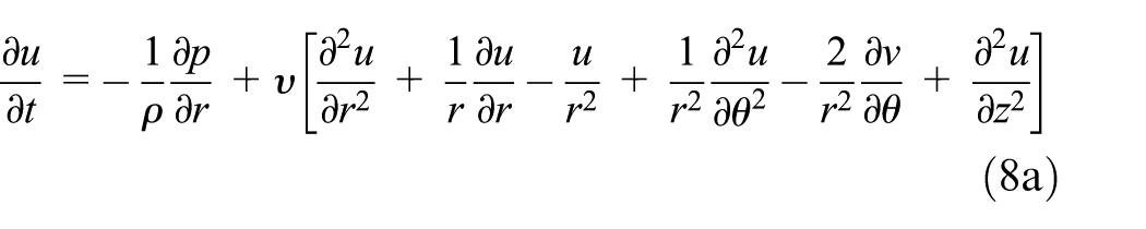

where p denotes the fluid pressure; u and v are the fluid velocity components along the radial and circumferential coordinate r and
For incompressible fluid, the flow must satisfy the equation for the conservation of mass written as

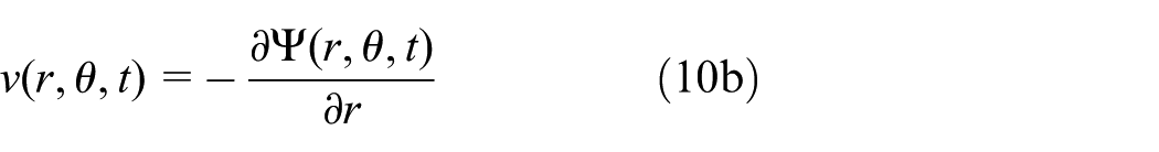
Since the objective is to determine the pressure distribution and the hydrodynamic resistance force, the velocity component can be written in terms of the stream function

The total velocity potential function

Introducing equations (10a) and (10b) and (11) into equation (8a) and (8b) gives the linearized Navier–Stokes equations for isothermal fluid in polar coordinates r and
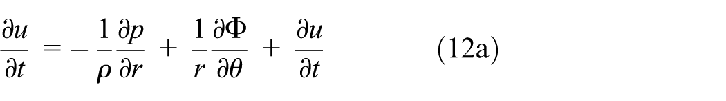

Ignoring the pressure term from equation (12a) and (12b) gives


This equation of fluid motion can be solved using the two stream functions


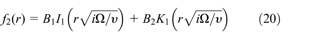
The solution of these equations may be written in the form 15

where
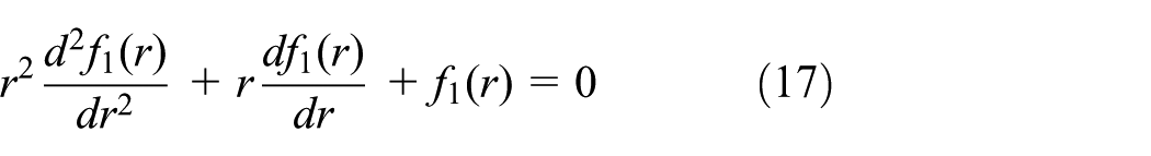

The solutions of these equations are, respectively, known as Euler’s and Bessel’s equations, where the solution to Euler’s is as follows 5

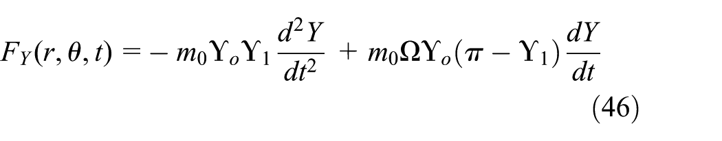
and Bessel’s equation yields Bessel functions of the first and second kinds as follows
where

The constants

Using equations 10(a) and (b), (21) and (22), the constants

where
Substituting in equation (21) gives

The resistance force to the rotation of the shaft, arising from the fluid viscosity, is

where the hydrodynamic radial and pressure distribution take the form


The major interaction between the fluid and the vibration system takes place at the disc–fluid interface. These forces are then transmitted to the rotating shaft. The following condition may be applied at the fluid free surface to the velocity potential (shaft and disc) with the assumption that the disc radius is approximately equal to the shaft radius
At
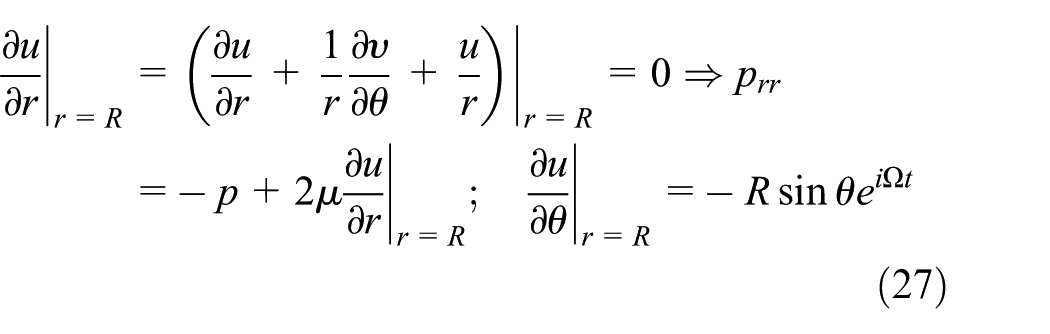

Adding equation (15a) and (15b) gives

Combining (28) and (29) gives

Introducing equations (28)–(30) into equation (26a) and (26b) gives


Equation (24), after using equation (31a) and (31b), becomes

The hydrodynamic force is obtained by integrating the obtained pressure distribution over the projected rectangular length L and rotor area as

Integrating the first term by parts and using relations (30), (31a), (31b) and (32) yields the following result

where
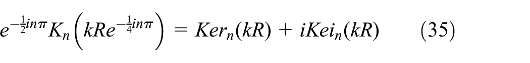
for
Thus

and

defined by
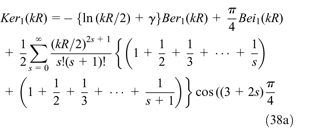
and

and


where


The above formulations are used by considering the physically meaningful imaginary part of the fluid force to determine the hydrodynamic force acting on the shaft obtained as follows

where
where

Dependence of hydrodynamic force in the x-direction with respect of the rotor speed: (a) fluid resistance force at Ω < 15 r/min, (b) fluid resistance force at Ω < 40 r/min and (c) temporal evolution of the viscous fluid force versus speed.
It is seen from Figure 3 that the amplitude of the resistance forces increases as the Reynolds number increases. In both cases, the fluid viscosity and the frequency of rotor oscillation bring the fluid dynamic response into bounded values at resonance as expected. Depending on the rotor speed, the fluid resistance force when plotted differs greatly in magnitude as observed in Figure 3(c). The hydrodynamic force component over the projected area is

where
The behaviour of the rotor in response to fluid motion is determined by the transformation of hydrodynamic forces to the Cartesian coordinates OXY. It is achieved by considering the coordinates of the shaft centre along the X and Y axis expressed as
After the consideration of the fluid inertia and fluid damping introduced by an immersed circular shaft, the hydrodynamic resistance force along the X and Y directions can be rewritten into

where fluid mass and damping coefficients per unit fluid depth are given by the following expressions

and

The nonlinear fluid mass and damping terms are incorporated into the equations of motion of the rotor system. Therefore, the analysis of the dynamics of the rotor filled with viscous fluid is obtained by coupling equations (45) and (46) within the lumped mass equation (7) to provide the final expression of the equation of the spinning rotor in a viscous fluid as follows

These results show that the dynamic force is rotating at the angular speed
Introduction of a crack and rub forces into the model
Rotor–stator rub forces
The derivation and rationale for mathematical model of rotor–stator rub-impact used in this article have been discussed in detail in Tchomeni 16 and are briefly presented herein. For the rotor–stator rub, in addition to the excitation forces along normal and tangential directions, the friction torque is also acting on the disc (Figure 4).

Geometry of rotor–stator forces and a clearance in fluid medium.
The radial and tangential rub-impact forces


where


And finally, expressed in the expanded form as


The obtained rub forces are further included in the generalized force vector {F} of governing equation and should be applied at particular DOFs corresponding to the disc location.
Dynamic model of rotor system with transverse crack
One of the objectives of this article is to investigate the contribution of the nonlinear damping and inertia terms of the viscous fluid to the response of a cracked rotor model. By imposing time-varying stiffness to simulate a breathing crack on a rotating shaft, the mathematical parametric excitation model of the rotor system with a breathing function of transverse crack for this investigation is similar to that used by Sekhar and Prabhu 17 as expressed in the stationary coordinate system O-XYZ as follows

where the rotational frame is mapped into the inertial frame by transformation matrix

n is the number of terms that contain the cosine in the summed series;
Mathematical model properties
In order to have a model that is sufficiently realistic, the baseline numerical simulation values of the geometric and physical properties of the rotor and viscous system used are given in Table 1.
Physical and geometric properties of the current rotor system and fluid model.

Numerical simulation results and discussion
Numerical simulations were performed using equation (47a) and (47b), in order to better describe the dynamics of the fluid–rotor system. Results of these simulations were compared to those of the simulations achieved based on the model without the nonlinear fluid properties modelled in equation 46. The balanced rotor system with and without nonlinear inertia and damping fluid terms is initially investigated. The coupled lateral deflection and rotating rotor vibration responses, orbit pattern and frequency spectrum are plotted for the fluid–rotor interaction analysis. Features of the steady-state rotor vibration response are extracted and analysed when unbalance, rub and crack exist individually and further when all faults are coexist to provide useful information on the fault diagnosis in viscous fluid environment.
Response of balanced rotor
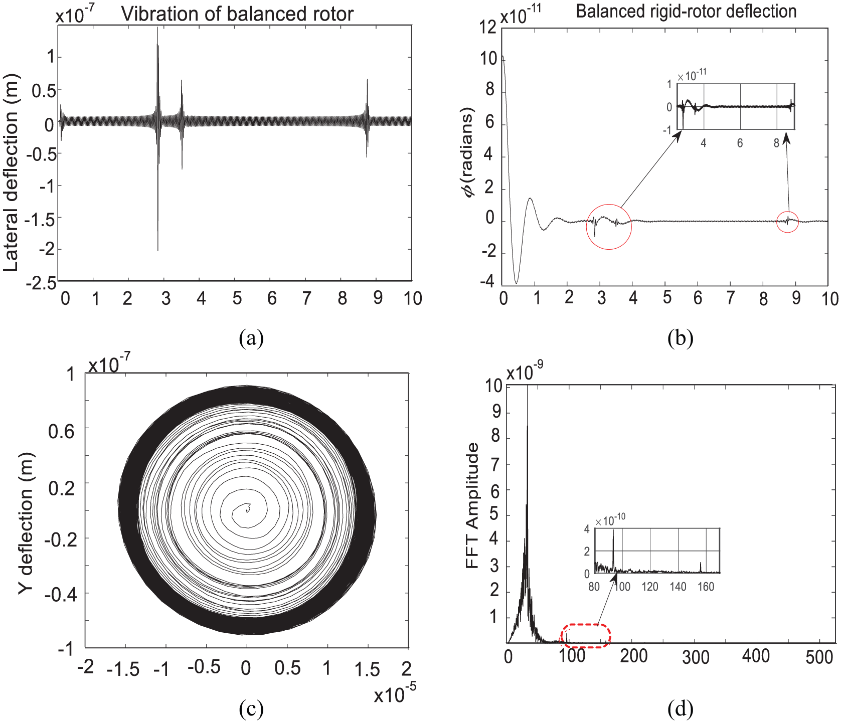
This section presents the baseline data results of a numerical simulation performed on a balanced rotor system. Furthermore, the influences of viscous fluid effects are considered in a subsequent simulation. The coupled lateral deflection and rotating shaft vibration responses, the orbit of shaft centre and the frequency spectrum of the response performed for rotational speed ratio 0.01 < Ω < 5 are presented in Figures 5 and 6.
Vibration signals of balanced rotor without fluid: (a) Time (sec), (b) Time (sec), (c) X-deflection (m) and (d) Frequency (Hz) are omitted.

Vibration signals of balanced rotor in viscous fluid: (a) Time (sec), (b) Time (sec), (c) X-deflection (m) and (d) Frequency (Hz) are omitted.
Figure 5(a) presented three peak components of resonances extracted from the lateral deflection; the first from the vibrations and oscillations of the rigid rotating shaft, and the similar two others represent the lateral deflection (X, Y). They are further decomposed into frequency components as illustrated in Figure 5(d). Figure 5(b) shows the system rigid-rotor response, which exhibits an exponential attenuation of the rotating shaft until the stability of the vibration becomes effective. The vibration response of the rotating rotor eventually dies out regardless of the excitation with the appearance of the resonance peaks, and a periodic and regular closing loop of the orbit in Figure 5(c) verified the typical feature of a stable dynamic system. Unlike the previous investigation in Figure 5, the present analysis using the nonlinear inertia and damping fluid terms do not produce a circular cycle of oscillations, and the shaft orbit displayed in Figure 6(c) is distorted and not regular in Figure 5(c). When viscous fluid effect occurs in a rotor system, the lateral vibration responses are highly distorted and cease to be pure harmonic signals as shown in Figure 6(a). However, due to the fluid the rigid-rotor motion becomes periodic, this difference should be attributed to the low motor speed which obliges the flow to be laminar.
With regard to the presence of multiple frequency peaks observed in Figure 6(a), the present simulations using nonlinear inertia and fluid damping terms display the variation of the signal through lateral deflection response, orbit and frequency spectrum. In spite of the fact that the hydrodynamic force acting as a resistance damping, this high presence of peaks is attributed to the differences in the behaviours of the rotating rotor damper and the hydrodynamic dampers. Moreover, apart from the basic harmonic of 50 Hz observed both in Figures 5(d) and 6(d), there are second and third harmonics encircled in the graph of the frequency spectrum. However, these frequency features are not different. This can be explained by the fact that the fluid oscillation period is the same as the periodical rigid-rotor vibration, which is consistent with equations (7) and (46). Through the analysis of both cases, the rotor motions are characterized as periodic and quasi-periodic depending on the hydrodynamic force which inherently lowers the frequency harmonics.
Response of unbalanced rotor system
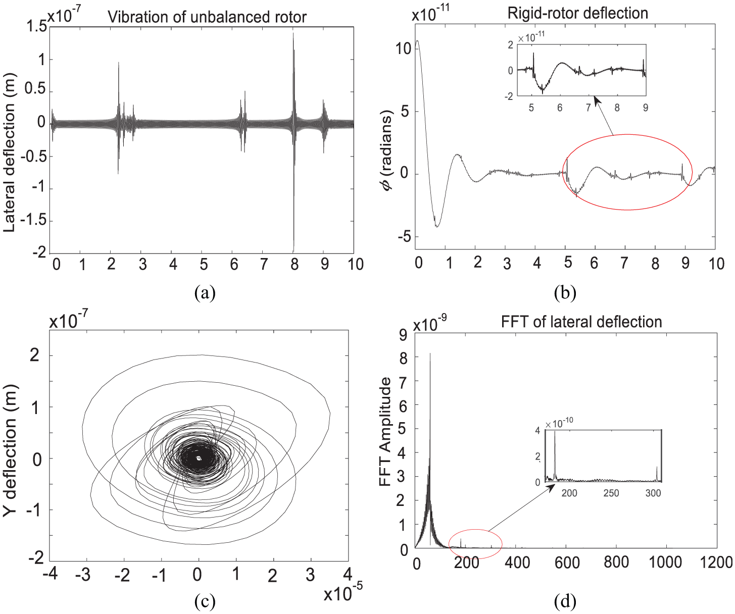
Simulations conducted in this section consider immersion of the unbalanced rotor in a viscous fluid. The excitation is an unbalance incited from a mass mu located at the mid-span in a radius e1. In order to compare and analyse accurately, the same data from the previous section ‘Response of balanced rotor’ (Figures 5 and 6) are selected, and the plots and analysis of vibration responses of unbalanced rotor system with and without fluid interaction are shown in Figures 7 and 8 using the orbit of the shaft and the frequency spectrum of the displacement of the shaft.
Vibration signals of unbalanced rotor without fluid: (a) Time (sec), (b) Time (sec), (c) X-deflection (m) and (d) Frequency (Hz) are omitted.

Vibration signals of unbalanced rotor with fluid: (a) Time (sec), (b) Time (sec), (c) X-deflection (m) and (d) Frequency (Hz) are omitted.
Comparison of the unbalanced rotor system with the previous balanced rotor system shows some similarities. In both cases, the frequency spectrum results are (main localized frequency at 1× order harmonic) similar to the conclusion reached for balanced rotor system, whereby the oscillation period of the rotating shaft is almost the same as the shaft rotating period in fluid medium as illustrated in Figures 7(d) and 8(d). Each frequency spectrum presents three frequency resonances (observable after a zoom) at approximately the same frequency magnitudes. Moreover, this comparison also addresses the coupling effects between the lateral damping and the fluid damping, which exhibits more resonance peaks in Figure 8(a) as well as zoomed frequency spectrum in Figure 8(d). Simultaneously, the disturbance in the orbits pattern reveals that the shaft centre orbits presented in Figures 7(c) and 8(c) are not regular circles anymore. Figure 7(b) reveals that the vibration of the rotating rotor is irregularly disturbed by the presence of multiple peaks due to the centrifugal force effects. It can be noticed from Figure 7(a) that the unbalance mass causes an increase in the peaks of resonances of the lateral response for fault conditions which increases significantly in viscous fluid.
Response of unbalanced rotor–stator rub
The response for the unbalanced rotor and the effects of nonlinearities generated by the rotor–stator interactions are investigated, and their sensitivity to the fluid parameters is compared. From the previous simulation (Figure 5(c)), the maximum response vector is found to be

Vibration signals of unbalanced rotor with rub without a fluid: (a) Time (sec), (b) Time (sec), (c) X-deflection (m) and (d) Frequency (Hz) are omitted.
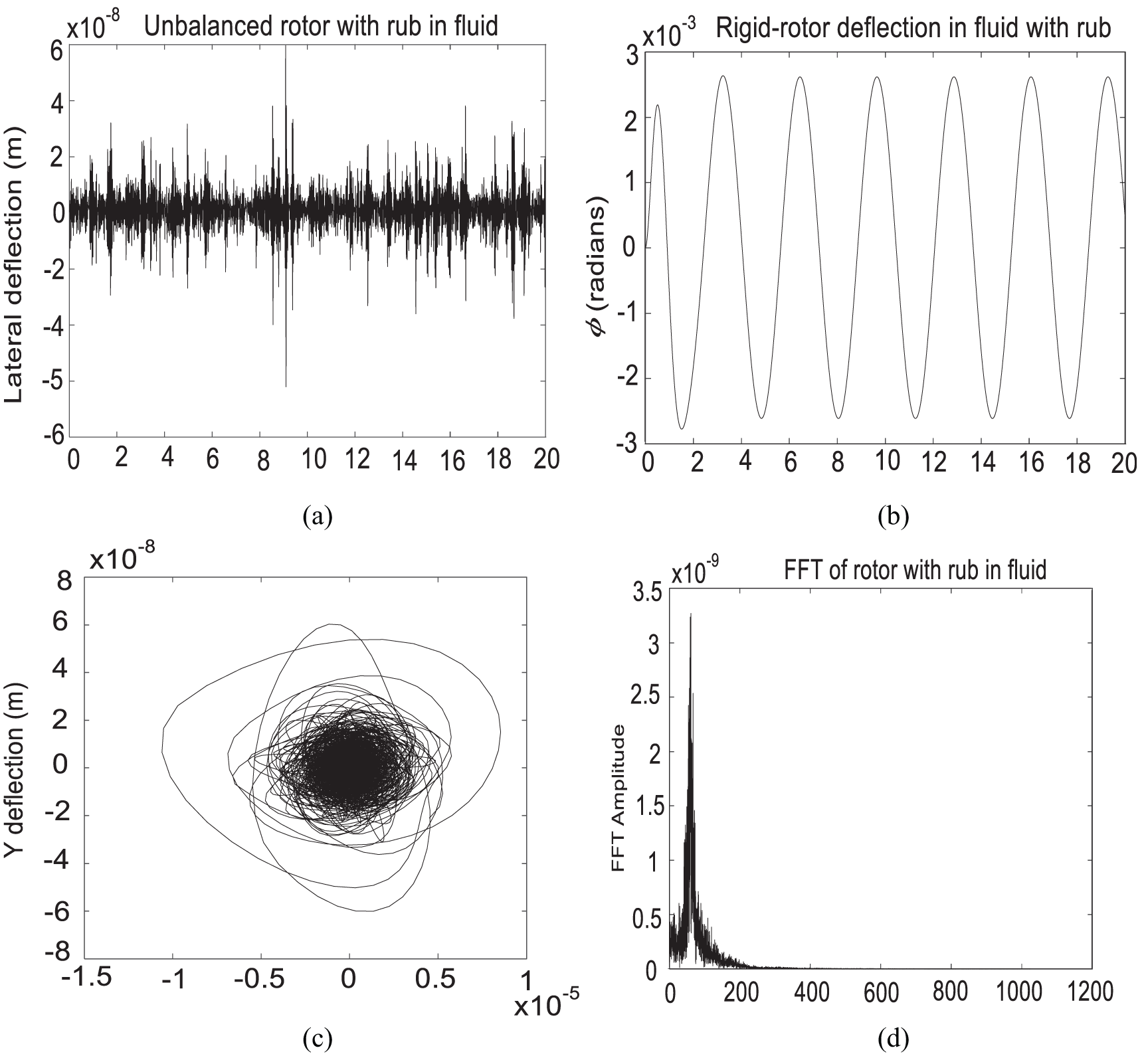
Vibration signals of unbalanced rotor with rub in fluid: (a) Time (sec), (b) Time (sec), (c) X-deflection (m) and (d) Frequency (Hz) are omitted.
Figure 9 presents the responses of the unbalanced rotor system with a recurrent rotor–stator contact, and the corresponding response of the rub model immersed in viscous fluid is shown in Figure 10. There are two significant differences between the two figures and one interesting similarity with the previous results. First, in Figure 9(d), the unbalance in the frequency spectrum is mainly localized at 1× order harmonic (50 Hz) as found in the previous section, followed by the 2×, 3×, 5× and 7× super-harmonics. This result is significant because frequency spectrum response showed that rub in rotor–stator excites high-frequency components with an equally periodical mode at different magnitude levels.
The intensity of rub-impact is attenuated with the effects of nonlinear fluid inertia and damping terms. Figure 10(d) shows that the effects of nonlinear fluid damping attenuate the higher rotor–stator contact, which appears to have nearly the same rate of growth as frequency response in original frequency in Figures 5(d) and 7(d). Extraction of features when the rub aperiodically occurs can be effective by analysing the lateral deflection of the rotor system in Figure 9(a), which is quite redundant in peaks appearance. However, the presence of the viscous fluid diminishes the rate of the rub frequency and the frequency spectrum magnitude.
The circular loops observed in Figure 5(c) for a balanced rotor exponentially differ from the orbit response of the unbalanced rotor system with rub. The observation of the orbit response revealed the degree of disturbance of the rotor system during impact. The orbit loops are quite disrupted with chaotic features as seen in Figure 9(c), which vibration phenomena are propagated along the rotor’s lateral deflection and the vibrating rigid-rotor response as shown in Figure 9(a) and (b), respectively. However, the observed higher level of vibrations, due to the rub effect in Figure 10(c), has significantly decreased in amplitude in the presence of viscous fluid.
In addition, the features of the vibrating rotor response presented in Figure 9(b) differ from the previous only by the presence of multiple peaks which are repeated along the signal. This can be explained by the variation of dissipative energy provided by the nonlinear fluid damper (Cfluid) than that the lateral damper (Cx). A particular observation made is the similarity between the rotor vibration angles
Response of unbalanced rotor with a transient crack
The dynamic analysis of the unbalanced rotor vibration response with a transverse crack is performed here. For the crack investigation, a value of the variation of stiffness

Vibration signals of unbalanced rotor with a crack: (a) Time (sec), (b) Time (sec), (c) X-deflection (m) and (d) Frequency (Hz) are omitted.
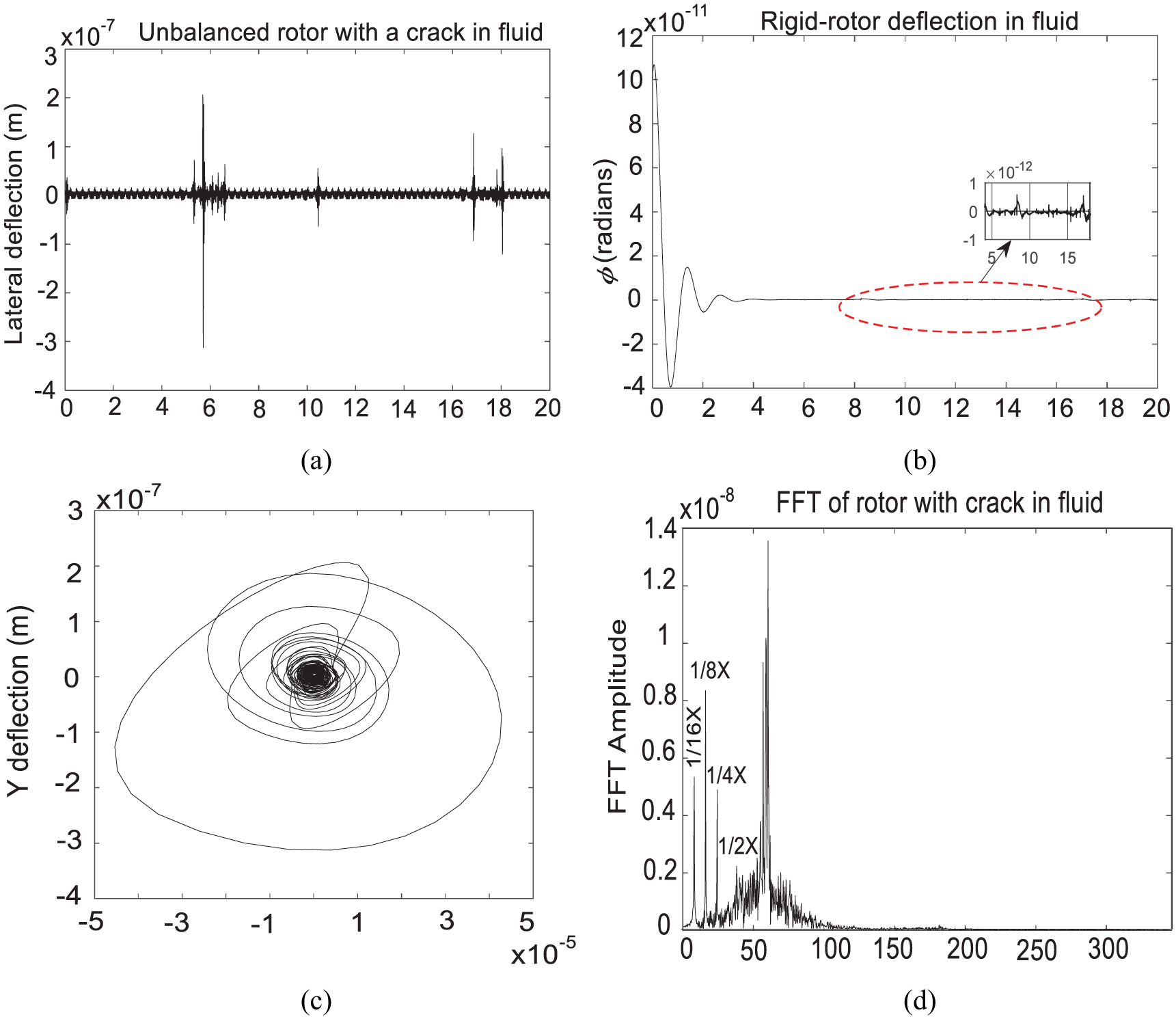
Vibration signals of unbalanced rotor with a crack in a fluid: (a) Time (sec), (b) Time (sec), (c) X-deflection (m) and (d) Frequency (Hz) are omitted.
The baseline condition obtained in the previous section and exhibited in Figures 5 and 6 is used to ensure comparable results for diagnostic features of crack and unbalance.
Figure 11(d) displays the frequency spectrum for unbalanced rotor system with a crack. It is obvious that if only unbalance effect is taken into account, the harmonic of 1× order remains unchanged, while the sub-harmonic 1/2× generated by cracked rotor system oscillates periodically, as shown in Figure 11(d). Similar features can be observed as the nonlinear inertia and damping effects exist as shown in Figure 12(d). Moreover, the vibration signals of the cracked rotor in the viscous fluid are apparently more chaotic. In Figure 12(d), the oscillated feature of frequency spectrum also validates that the highly oscillated sub-harmonics can qualitatively reveal the fluctuating rule of the transient stiffness for cracked rotor system. The transient effects of the cracked shaft are directly influenced by the depth of the crack and the nonlinear fluid terms, and the oscillated harmonic may be applied to qualitatively describe the breathing of the crack. Therefore, the oscillation feature of the harmonic can be considered as an index to monitor the occurrence of the crack.
Once the system overall rotating vibration reaches a point of neutral stability, the characteristic of convergence signal is evident as observed in both rotor vibration responses as illustrated in Figures 11(b) and 12(b). There is a significant difference between the two figures. In the absence of the fluid, the vibration levels are large enough and present the existence of multiple peaks as a characteristic of transient crack presence (Figure 11(b)). It appears that following the effect of a crack, a progressive decay of the rotating vibration response due to the viscosity of the fluid is seen. An observation of the plots shows that the vibration responses of the immersed system shown in Figure 12(b) are not similar in convergence to those observed previously in Figures 6(b), 8(b) and 10(b). The physical reason behind this can be that the nonlinear terms due to a transient crack are small enough to be neglected and the loss of energy from the oscillatory cracked shaft results in a decay of the rotor vibrations amplitude. The loss of energy of cracked shaft is balanced by the energy which is supplied by the system’s excitation. The dissipative energy can be illustrated here under conditions of cyclic oscillations. This may be referred to the hysteresis closing loops in Figures 11(c) and 12(c), which in essence is proportional to the energy lost per cracked rotor cycle.
The fact that the hydrodynamic force is strongly nonlinear affects the rotor motion by reducing the synchronous harmonics of the driving rotor’s frequency (Figure 11(d) to higher asynchronous harmonic frequency as shown in Figure 12(d). This fact depends on the rotational speed of the rotor and the unbalance force. Therefore, the amplitude of perturbation responses in the fluid medium is small compared to a free vibration response. The frequency analysis provides the development of hyper harmonics with frequencies 1/2×, 1/4×, 1/8× and 1/16× in viscous medium. The estimated orbit loops are given by the area enclosed by the disturbed ellipse as shown in Figures 10(c) and 12(c). In the presence of the eccentric mass and the transient stiffness, the closing loops are not so organized compared to Figure 5(c). Moreover, it is less certain to extract with accuracy features of the crack effects by analysis of Figures 11(a) and 12(a). However, all these changes in features are easily buried in inevitable noise, and the cracked rotor signal is corrupted and masked by signal’s noise, which makes its detection complex and difficult.
In order to proceed with further data analysis, noise features must be removed from the obtained signals. A new algorithm called wavelet denoising technique 18 is used to denoise the oscillation signal and qualitatively describe the oscillated feature of transient stiffness. From this proposed technique, it is possible to increase estimation and precision of the corrupted signal, particularly in extracting and appreciating the features of the crack. The amplitudes either in time-domain or frequency-domain are really sensitive to the local flexibility of the shaft. There is obviously evidence of crack effects illustrated by the presence of wide small peaks throughout the lateral deflection, which diminish in the viscous medium as observed in Figure 13(a) and (b).

Denoised signals of unbalanced rotor with a crack in viscous fluid medium.
Response of combined unbalance, rotor–stator rub and a crack
The purpose of this section is to study the fluid coupling structure between a fluid and a rotor on which the rotor is assumed to have multiple faults. This analysis includes fluctuating fluid forces acting on various vibration phenomena encountered in rotating machines due to a combination of faults such as unbalance, crack and rub. The mechanisms of vibrations of rotors partially filled with viscous fluid and vibrations induced by each combined faults are investigated and discussed in Figures 14 and 15. It is clear that the system response experiences considerable changes due to the presence of the rub-impact and a crack. The overall vibration level is observed to be high than the previous simulation (unbalance-crack and unbalance-rub rotor).
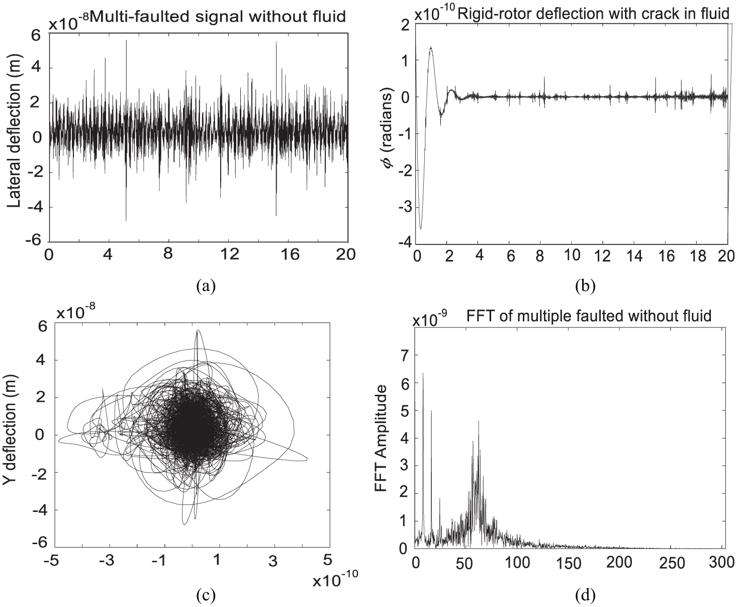
Vibration signals of unbalanced rotor–stator rub with a crack: (a) Time (sec), (b) Time (sec), (c) X-deflection (m) and (d) Frequency (Hz) are omitted.
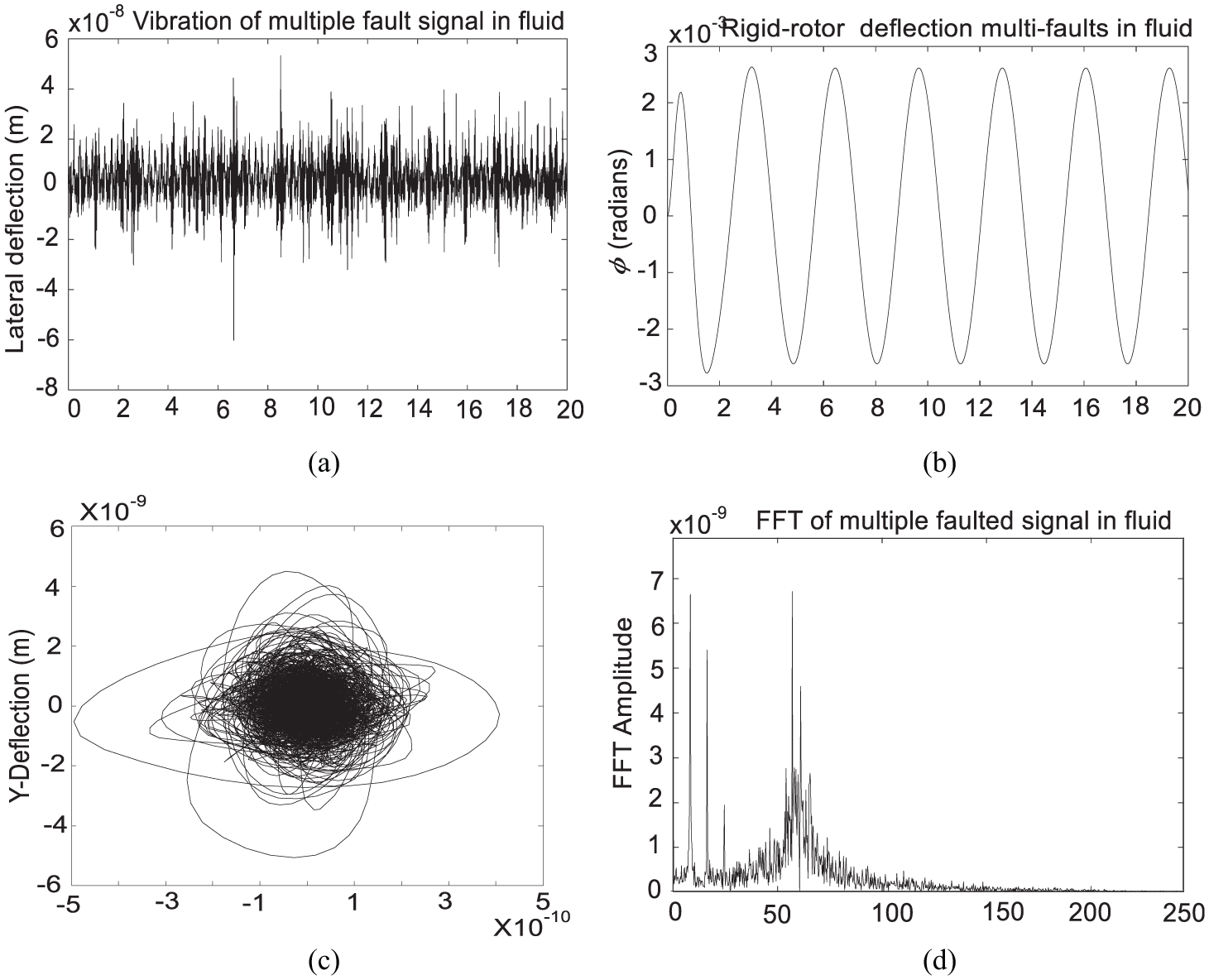
Vibration signals of unbalanced rotor–stator rub with a crack in fluid: (a) Time (sec), (b) Time (sec), (c) X-deflection (m) and (d) Frequency (Hz) are omitted.
Extracted features of the mixed faults of the system with and without nonlinear inertia and damping fluid terms are significantly different. By comparing the response of the overall rotating rotor vibrations in Figure 14(b) with the response in Figure 15(b), the periodical rigid-rotor vibrations are now more evident as observed in the previous analysis in fluid medium. It would be unreasonable to suggest that the differences between the response in Figures 6(b), 8(b), 10(b) and 15(b) are due uniquely to the variations in viscous damping. The smaller peaks of frequencies appear once the rotor contacts the stator. With an aperiodic shaft rotation, occurrences of the rub can roughly dominate the transient feature of the instantaneous stiffness for cracked rotor system as observed from Figure 15(b). The most dramatic changes in features appear in the orbit responses signals, which, are apparently strongly disturbed as shown in Figure 14(c). It can be seen from orbit patterns that chaos in this system is generated both by a gradual contact of the rotor to the stator combined with the compressing and stretching apart of transient stiffness over the rotors. Compared to multiple faulted system without fluid terms in Figure 14(c), the response in Figure 15(c) qualitatively showed the low amplitude of fluctuations of the orbit and quantitatively described the reduction of the transverse crack and repetitive rub-impact effect in viscous medium.
Moreover, these curves obtained in Figure 14 allow to highlight the effect of damping provided by the fluid viscosity on the response spectrum in presence of the rotor–stator contact and cracked rotor effect. As mentioned above the nonlinearity of hydrodynamic forces, combined with the transient breathing of the crack and the rubbing forces can be amplified and detected depending on the rotational speed of the motor. The decrease in the amplitude is very marked. The difference in the peaks of frequency magnitudes is very small when various faults coexist in viscous fluid as in Figure 15(a) compared to Figure 14(a). It is also evident that the lateral deflection does not reveal, as one might expect, the fluctuating features of the transient stiffness of cracked rotor system. When unbalance, crack and rub coexist, crack monitoring becomes more difficult in lateral deflection.
The rub effects virtually dominate the lateral vibration signal, but the frequency spectrum reveals the prominence of sub-harmonic peaks which exhibit higher amplitudes as shown in Figures 14(d) and 15(d). The crack introduces higher harmonics in the time response of the rotor, but its effects here are less obvious and obstructed by the higher fluctuation of rub-impact. Therefore, an observation from the denoised signal in blue in Figure 16(a) and (b) included not only the recurrent peaks of rub but also the repetitive peaks of the cracks feature along the whole lateral deflection signal.

Vibration response of denoised signals in lateral direction with unbalance, rub and a crack faults: (a) original of multiple faulted signal without fluid, denoised of multiple faulted signal without fluid and (b) original multiple faulted signal in fluid, denoised multiple faulted signal in fluid.
However, as the results of the investigations noted above, it is evident that the time-domain analysis and frequency spectrum are not sufficient enough to reveal some irregularities and imprecise fluctuations as various faults coexist in the rotor system. It can be noted from the entire investigation that there exist considerable mismatches in frequency spectrum results, which is not yet enough to extract with accuracy the feature difference of both time and period of rub occurrences. The shortcoming of these diagnosis methods for analysing a nonlinear signal from a rotor system in viscous medium might necessity further the use of a robust technique which provides higher accuracy for the extraction of features of complicated and mixed signals.
Conclusion
A dynamic model of a rotor–fluid system taking into account the nonlinear hydrodynamic inertia and damping terms was developed and investigated. The vibration behaviour of long rotating shaft such as sub-marine high-speed turbine rotor or other marine structures machines with primary rotary inertias is described by this simplified equivalent configuration and used for fault identification. The numerical simulation of the rotor system operating in incompressible viscous fluid yielded results that demonstrate the effect of nonlinear hydrodynamic inertia and damping terms on the dynamic rotor vibration. Five specific areas of investigation were addressed: (1) the effect of the coupled lateral deflection and rotor vibrations of an unbalanced rotor system; (2) the effect of the nonlinear inertia and damping fluid; (3) the effect of rub occurrences in the rotor–stator; 4) the effect of the transient stiffness of the cracked shaft on vibration response; and (5) the combination of nonlinear inertia and damping fluid terms with simultaneous consideration of unbalance, rub and crack coexisting in the rotor system. As a result of investigations conducted in this article, the nonlinear inertia and damping fluid terms were identified among the sources of coupling between the lateral and rotational vibrations. The terms have significant influences on the rotating system such as vibration attenuation and fluid–rotor stability.
Analysis of nonlinear lateral deflection showed that the rotor response grows at approximately the same rate irrespective of the fluid medium around the shaft. Therefore, the viscous fluid acts as a vibration damper. However, the frequency spectrum of the balanced system and unbalanced one in viscous are quite similar. This is somehow a surprising result since the energy dissipation of eccentric effect for an unbalanced system was higher than that for corresponding balanced system inside the fluid medium. The difference between frequency spectrum results of coexisting fault behaviours in fluid and out of fluid was insignificant. The study also revealed that nonlinear fluid damping has a stabilizing effect on the cracked shaft vibrations. The frequency spectrum response, rigid-rotor deflection and the orbit response of the unbalanced rotor with a crack, respectively, exhibit distinguishable features between the rub and crack.
The hydrodynamic excitation forces caused excessive stresses that initiated and propagated crack features along the rotor deflection shaped, which is well observed through the denoised signal. The denoised lateral deflection signal reveals with accuracy the non-stationary nature of the rotor–stator contact and features of the crack. Simulations of fluid–rotor interaction revealed that the coupling effect of fluid is a powerful factor in reducing the higher amplitude fluctuations of the vibrating system. The results of the numerical simulations raise a question of sophisticated time–frequency technique to overcome certain limitations of the diagnostic technique used due to the high nonlinearities in the fluid–rotor system. More numerical and experimental analyses are required to validate these results.
Footnotes
Acknowledgements
The authors appreciate the support of the Department of Mechanical Engineering at Vaal University of Technology (South Africa) for providing resources and equipment to make this work possible.
Handling Editor: Yong Chen
Declaration of conflicting interests
The author(s) declared no potential conflicts of interest with respect to the research, authorship, and/or publication of this article.
Funding
The author(s) received no financial support for the research, authorship, and/or publication of this article.