
Abstract
The optimum polishing traces are the double-circle polishing traces with zero-velocity deviation percentage (Vdp = 0%). In 1997, Buzzetti used the relatively high-cost programmable logic controller to control the polishing device having double-circle polishing traces with zero-velocity deviation percentage. In order to reduce the manufacturing cost, link-type and planetary-type polishers are proposed for polishing the optical fiber ferrules. However, they cannot be designed to have the double-circle polishing traces with zero-velocity deviation percentage. This article focuses on the systematic design of polishing device having double-circle polishing traces with zero-velocity deviation percentage (Vdp = 0%). In this article, two design concepts of cam-linkage polishing devices are proposed. Based on the kinematic requirements of double-circle polishing traces, the profiles of X-cam and Y-cam are synthesized. According to the simulation by “Cosmos,” the cam-linkage polishing devices have double-circle polishing traces with zero-velocity deviation percentage. Finally, the corresponding prototype of the second cam-linkage polishing device is manufactured and verifies having double-circle polishing traces with zero-velocity deviation percentage.
Keywords
Introduction
The mechanical devices for polishing optical fiber ferrules (or wafers) can be roughly divided into the planetary-type mechanisms1–6 and the link-type mechanisms.7–9 The planetary-type polisher provides donut polishing traces and link-type polisher provides eight-shaped polishing traces. When polisher follows eight-shaped traces or donut traces, the polishing directions will be continually changed, as a result the polishing quality will be enhanced. If the polisher follows a straight line, the polishing direction does not change and results in poor polishing quality. Another factor that affects the polishing quality is velocity deviation percentage (Vdp) which will be introduced in the next section. Some studies focused on the velocity deviation percentage (Vdp).3–9 The Vdp represents the changing rate of polishing velocity, and the smaller Vdp, the higher polishing quality. Hence, the double-circle polishing traces with zero-velocity deviation percentage (Vdp = 0%) is our design target.
The purpose of this article is the systematic design and prototype verification of cam-linkage polishing devices double-circle polishing traces with zero-velocity deviation percentage (Vdp = 0%). First, according to creative design of mechanical devices9–11 and Osborn checklist method,12–15 two inventions of “Cam-Linkage Polishing Device” are proposed in this article. Based on the kinematic requirements of double-circle polishing traces, the profiles of X-cam and Y-cam are synthesized. According to the results of profiles of X-cam and Y-cam, the engineering designs of two cam-linkage polishing devices are accomplished. Simulating by “Cosmos,” two cam-linkage polishing devices have double-circle polishing traces with zero-velocity deviation percentage (Vdp = 0%). Finally, the corresponding prototype of second design concept is manufactured and verifies having double-circle polishing traces with zero-velocity deviation percentage (Vdp = 0%).
Polishing devices
The velocity deviation percentage (Vdp) is defined as the percentage of the deviation range divided by the average velocity.3–9 Thus
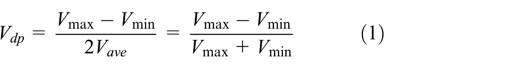
The velocity deviation percentage (Vdp) is another factor which affects the polishing quality. The value of Vdp means that change rate of polishing velocity, small value of Vdp, will produce high polishing quality.
The planetary-type mechanism, shown in Figure 1(a), has 2 degrees of freedom and its ring gear and planet arm are the two inputs to get donut polishing traces. Figure 1(b) and (c) shows the different donut traces of points A and B on the grinding disk, that is, different positions on the grinding disk will have different donut traces and have different polishing qualities. Hsieh and Chen 6 propose that planetary-type polishing devices that all point on the grinding disk have the same donut traces. And, the velocity deviation percentages (Vdp) of planetary-type polishing devices are between 1.7% and 58.1%.
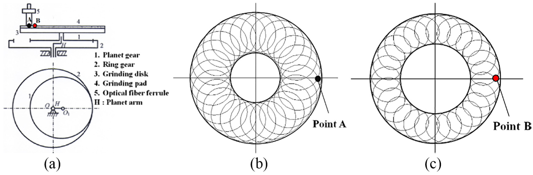
Planetary-type polishing device (Vdp = 1.7%–58.1%): (a) kinematic skeleton, (b) polishing traces of point A, and (c) polishing traces of point B.
Figure 2(a) and (b) shows the kinematic skeleton and polishing traces of a link-type polishing device. 8 The mechanism of link-type polishing device, shown in Figure 2(a), has 2 degrees of freedom and its links 2 and 6 are the two inputs (having the kinematic constraint “Δθ6 = 2Δθ2”) to get eight-shaped polishing traces with Vdp = 76.9% and three straight line segments (red line), as shown in Figure 2(b). Based on the research of Hsieh and Chen,8,9 the velocity deviation percentages (Vdp) of link-type polishing device are between 36.6% and 76.9%.

Link-type polishing device (Vdp = 36.6%–76.9%): (a) kinematic skeleton and (b) polishing traces.
However, the link-type and planetary-type polishing devices cannot be designed to have zero-velocity deviation percentages (Vdp = 0%). The optimum polishing traces, shown in Figure 3, is double circles with zero-velocity deviation percentages (Vdp = 0%). Buzzetti 16 used the relatively high-cost programmable logic controller (PLC) to control the link-type polishing device to get polishing traces with double circles. In order to reduce the manufacturing cost, other patents17–19 of optical polishers are proposed.

The optimum polishing traces with double circles (Vdp = 0%). 16
Based on the creative design of mechanical devices9–11 and Osborn’s check-list method,12–15 two cam-linkage polishing devices, as shown in Figure 4(a) and (b), can be designed to have zero-velocity deviation percentages (Vdp = 0%).
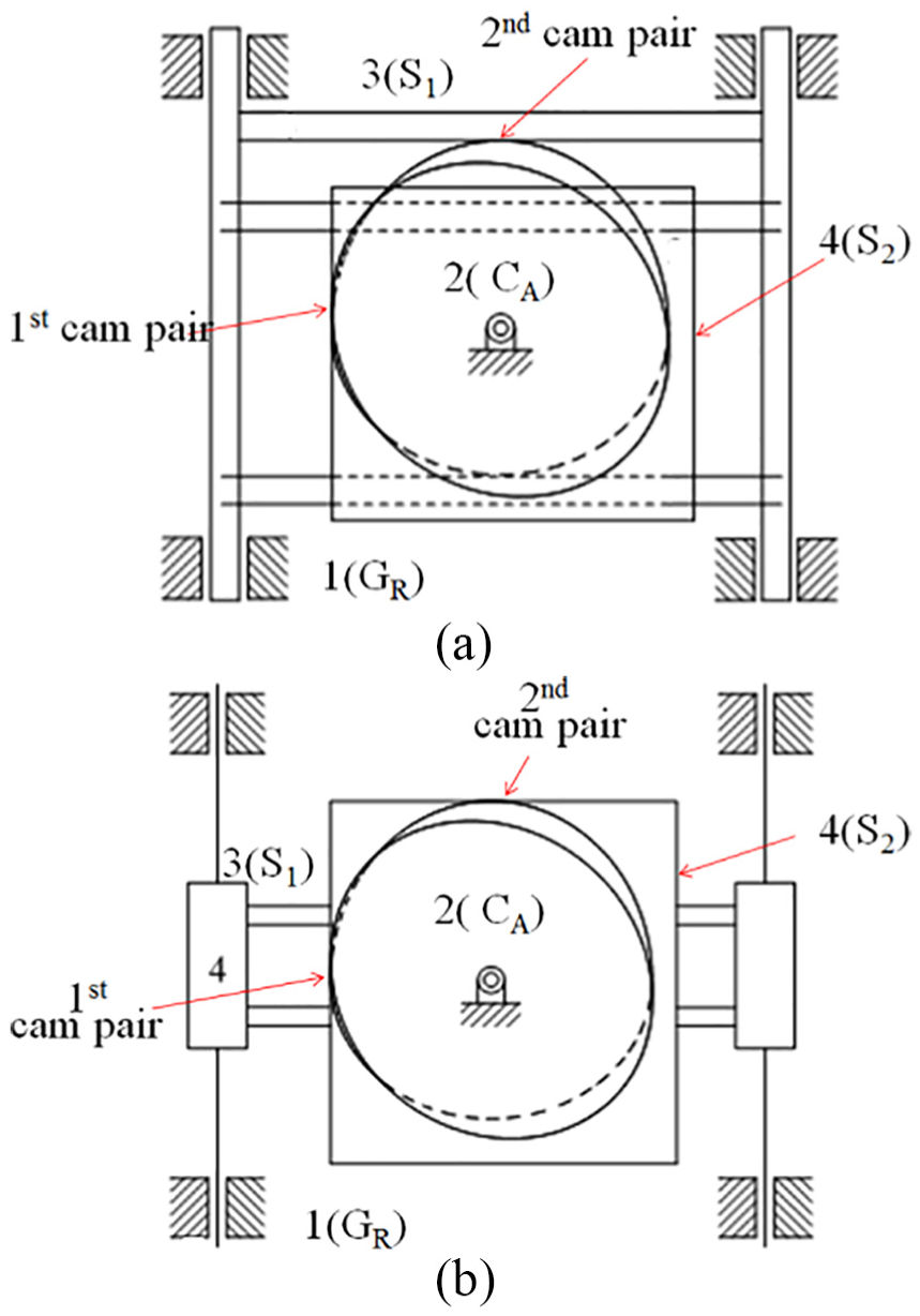
New design concepts of cam-linkage polishing devices: (a) first new design concept and (b) second new design concept.
Kinematics of grinding disk
The cam is a mechanical element with a special profile, and the follower will be driven to have the desired motion. The cam mechanism consists of cam, follower, and frame (ground link). It has the advantage of small size, compact construction, good dynamic performance, and easy design to meet motion requirements. It is widely used in automated machinery and plays an irreplaceable role.
Displacement of grinding disk
X-cam controls the displacement of grinding disk in X-direction, and Y-cam controls the displacement of grinding disk in Y-direction. By the special profiles of X- and Y-cams, grinding disk can provide the double-circle polishing traces, as shown in Figure 5. According to Figure 5, the coordinate (x, y) can be expressed as follows:
Circle I


Circle II


Double-circle polishing traces.
The relationship between the angles of the two circles (α, β) and angular displacement of cam (θ) can be as expressed as follows:
For α = 0°–360°

For β = 0°–360°

Substitute equations (6) and (7) into equations (2)–(5), we get


If r = 7.5 mm, θI = 0°–180° (α = 0°–360°), and θII = 180°–360° (β = 0°–360°), the polishing displacement curves of grinding disk in X-direction and Y-direction are shown in Figure 6(a) and (b).

Displacement curves of grinding disk: (a) X-direction and (b) Y-direction.
Polishing velocity of grind disk
Differentiate equations (8)–(11) by time, and the velocity equations in X-direction and Y-direction can be expressed as


where ω is the angular velocity of the cam.
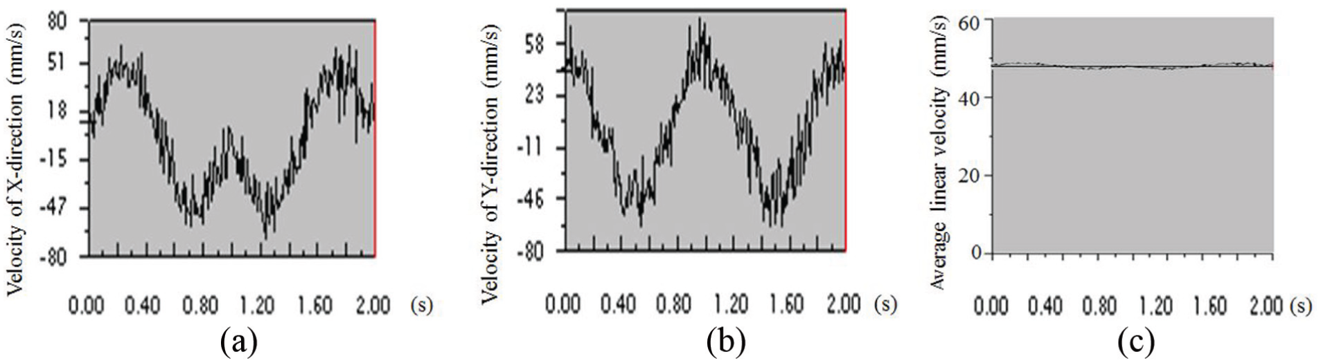
If r = 7.5 mm, θI = 0°–180° (α = 0°–360°), θII = 180°–360°(β = 0°–360°), and ω = 30 r/min, the polishing velocity curves in X-direction and Y-direction are shown in Figure 7(a) and (b).
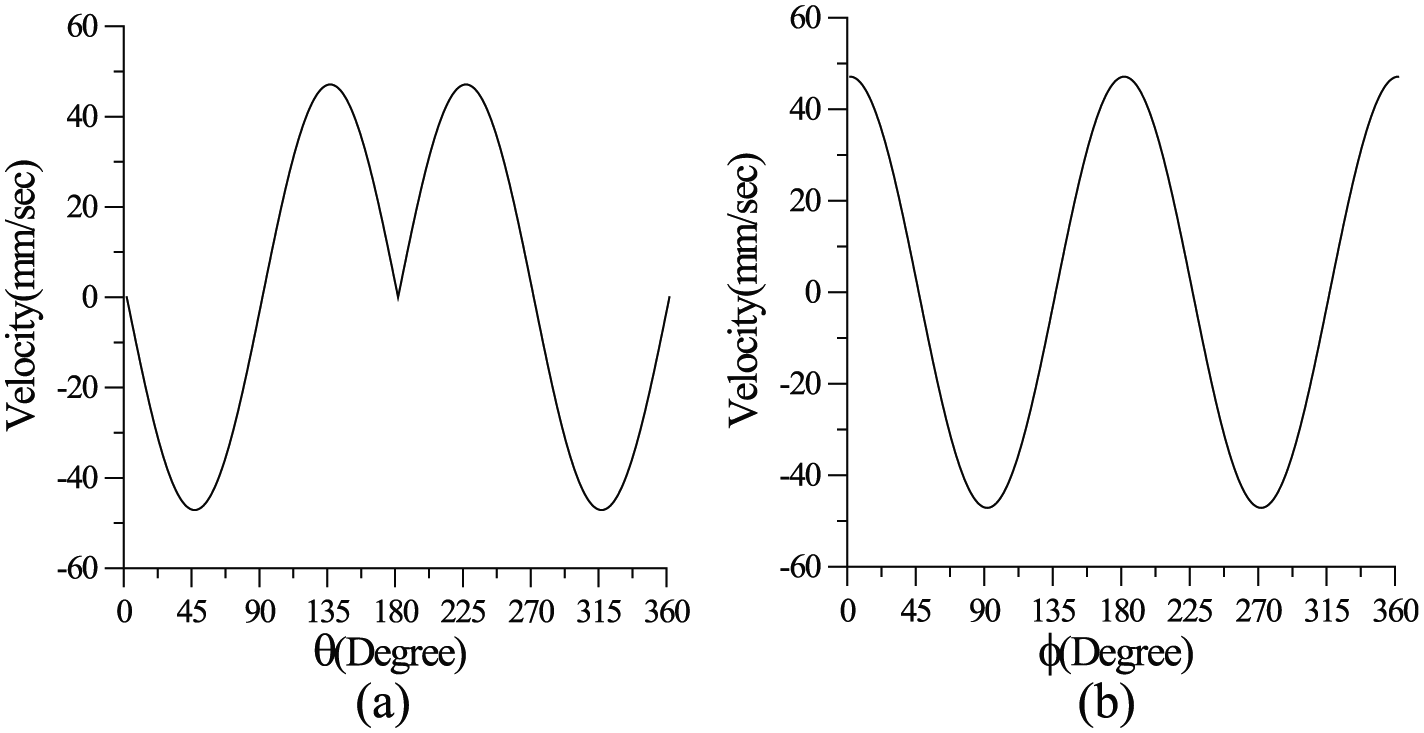
Polishing velocity curves of grinding disk: (a) X-direction and (b) Y-direction.
The polishing velocity of grinding disk can be expressed as

Substituting equations (12) and (13) into equation (14), the linear polishing velocity of grinding disk is obtained to be a constant value V = 47.12 mm/s, as shown in Figure 8.

Linear velocity of grinding disk.
According to Figure 8, the velocity deviation percentage of the cam-linkage polishing device is 0%, that is, Vdp = 0%. So, these two inventions “Cam-Linkage Polishing Device” have double-circle polishing traces with zero-velocity deviation percentage (Vdp = 0%).
Cam profile design
Figure 9 shows the cam mechanism with linear motion, coordinate system O-X-Y is fixed on the cam, and I12, I13, and I23 are instantaneous centers. Point Q is the instant center I23 and

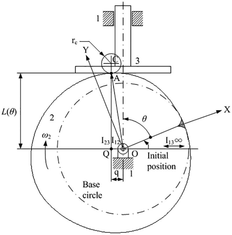
Cam mechanism with linear motion. 20
The position of follower “L(θ)” can be expressed as

where
According to Figure 9, we have the geometric relationship

where


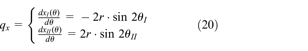
Differentiating equations (8)–(11) to θ, and substituting them into equation (15), we get the q values of X-cam and Y-cam (

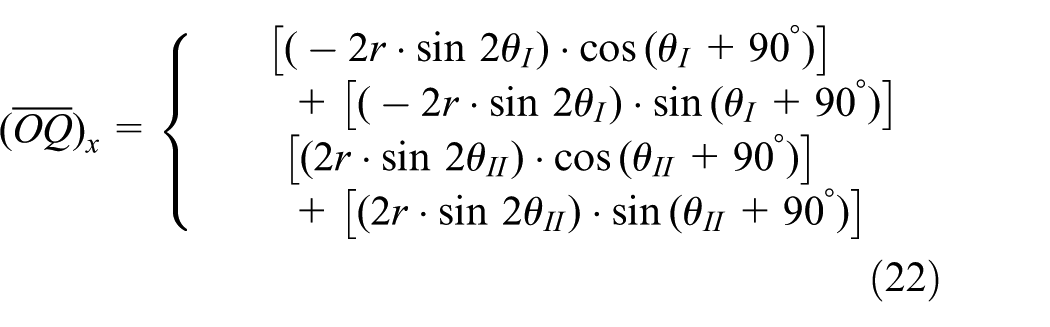
Substituting equations (20) and (21) into equation (18), we get

Then, substituting equations (8)–(11) into equation (16), the displacements of X-cam (L(θ) x ) and Y-cam (L(θ) y ) can be expressed as


Substituting equations (24) and (25) into equations (22) and (23), we get


If r = 7.5 mm, rb = 240 mm, θI = 0°–180° (α = 0°–360°), θII = 180°–360° (β = 0°–360°), the cam profiles of X-cam and Y-cam are shown in Figure 10(a) and (b).

Cam profiles of cam-linkage polishing device, considering r = 7.5 mm and rb = 240 mm: (a) X-cam and (b) Y-cam.
Engineering design and prototype verification
Engineering design
For the two design concepts shown in Figure 4(a) and (b), based on the results of the design of X-cam and Y-cam, the corresponding engineering designs are accomplished and shown in Figure 11(a) and (b). According to Figure 11(a) and (b), we conclude that the second design concept has less mechanical parts than the first design concept. Hence, the second design concept of the cam-linkage polishing device is chosen for manufacturing the prototype.

Cam-linkage grinding devices: (a) first design concept and (b) second design concept.
Dynamic simulation by “cosmos”
For the cam-linkage polishing devices shown in Figure 11, if the rotation speed of cam is 30 r/min, Figure 12(a)–(c) shows the corresponding simulation speed in X-direction and Y-direction and linear velocity of grinding disk. The linear velocities of grinding disk are almost near constant value “V = 47.12 mm/s.”Figure 13 shows the simulation polishing traces of grinding disk.
Polishing velocity simulation by “Cosmos”: (a) X-direction, (b) Y-direction, and (c) linear velocity.

Polishing traces simulated by “Cosmos.”
Prototype verification
According to the results of engineering design, the second cam-linkage polishing device is shown in Figure 14(a). Figure 14(b) shows the real polishing trace produced by prototype. According to Figure 14(b), we conclude that the cam-linkage polishing devices, proposed in this article, have double-circle polishing traces with velocity deviation percentage (Vdp = 0%).

Prototype and its real polishing traces: (a) prototype and (b) real polishing trace.
Conclusion
Traditionally, for link-type polishing devices, their velocity deviation percentages (Vdp) are between 36.6% and 76.9%, and for planetary-type polishing devices, their velocity deviation percentages (Vdp) are between 1.7% and 58.1%. This article focuses on the systematic design of polishing device having double-circle polishing traces with zero-velocity deviation percentage (Vdp = 0%). First, two design concepts of cam-linkage polishing devices are proposed in this article. Then, based on the kinematic requirements of double-circle polishing traces, the profiles of X-cam and Y-cam are synthesized. According to the results of the design of X-cam and Y-cam, the corresponding engineering designs are accomplished. Finally, the second design concept of the cam-linkage polishing device is manufactured and verifies that it has double-circle polishing traces with zero-velocity deviation percentage (Vdp = 0%).
Footnotes
Handling Editor: Jan Awrejcewicz
Declaration of conflicting interests
The author(s) declared no potential conflicts of interest with respect to the research, authorship, and/or publication of this article.
Funding
The author(s) received no financial support for the research, authorship, and/or publication of this article.