
Abstract
The effect of dynamic unbalance of the underframe suspended rotational equipment on the flexible vibrations of the carbody has become a major concern for high-speed trains. It is known from the field tests that the dynamic unbalance has a significant influence on carbody vibrations, especially the local flexible vibration, which leads to a decrease in the passenger ride comfort and may even cause structural damage to the carbody. A vertical mathematic model considering the carbody flexibility and the underframe suspended equipment is first set up, and then a three-dimensional dynamic model for a rigid–flexible coupled vehicle system is established. The effect mechanism of the dynamic unbalance on carbody flexible vibration is extensively studied, and the efficient measures to reduce the carbody flexible vibrations are proposed. The theoretical and simulation models are verified by comparing with a field test conducted on a newly designed high-speed railway. The results show that decreasing the unbalanced mass of the rotational equipment can reduce the carbody vibrations. Moreover, the use of elastic suspension for the underframe equipment can isolate the vibration transmission to the carbody. Both the theory of dynamic vibration absorber and dynamic unbalance should be considered to optimize reasonable suspension parameters, especially the suspension location and the suspension frequency.
Keywords
Introduction
Along with the speed increasing of high-speed trains, one of the main concerns is the carbody lightweight design. Lightweight can effectively reduce the interaction forces between wheels and rails, save energy, and lower the production costs.1–3 However, it may result in the decrease of structural rigidity of the body, increase of flexible vibrations and worsen the passenger ride comfort. Therefore, the issues of carbody vibrations considering the carbody elasticity have been paid much attention by researchers, especially for high-speed electric multiple units (EMUs).4–9 To meet the requirement of high-speed operation, power-distributed EMUs are used. Much equipment is hung on the carbody underframe including the traction transformer, cooling fan and braking unit, and so on. Some of these may weigh 3–10t and some may be the excitation sources, for instance, the air compressor. How to suspend the underframe equipment on the carbody underframe has been studied by many researchers.10–14 One reasonable method is the application of dynamic vibration absorber (DVA) theory to reduce the vibration of the carbody.15–17
Considering the effects of carbody flexibility and all vertical rigid modes, Zeng and Luo 10 established a mathematical model for a vertical vibration system with a rigid carbody, showing that the vibration of the carbody can be reduced with the underframe equipment acting as a DVA in a certain frequency band. Tomioka and Takigami 11 used the bogie longitudinal vibration as a DVA to reduce the carbody vertical bending vibration, which was proved to be effective by field tests. Based on the study of Shi et al. 12 and Luo et al., 13 the underframe equipment was regarded as a DVA and the effect of suspension parameters on carbody vertical vibration was studied. In addition, a roller rig test was conducted to validate the theory and simulation results. In the study of Gong et al., 18 a finite element (FE) model of a fully equipped high-speed railway carbody and a rigid–flexible coupled model including a flexible carbody was built and used to analyze the influence of underframe equipment on the modal parameters of the carbody. The results showed that the carbody modal frequencies are increased obviously with elastically suspended equipment and reasonable suspension parameters can effectively reduce the carbody flexible vibrations.
However, few studies have been undertaken for the effect of the dynamic unbalance of underframe rotational equipment on carbody elastic vibrations. The underframe equipment with dynamic unbalance sometimes vibrates with a much higher frequency19,20 and may have a greater impact on the carbody elastic vibration. Therefore, further research work is needed to study the coupling vibration of the carbody and the unbalanced underframe equipment.
In this article, a field test of an underframe suspension system is first described as the research background for a high-speed railway vehicle. The effect of unbalanced vibration of the underframe rotational equipment on carbody flexible vibration is discussed. Then, numerical studies are conducted based on a vertical mathematic model of carbody underneath suspended system and several parameters are studied. Also, a three-dimensional dynamic model of a rigid–flexible coupling vehicle system is established validated by another field test and the dynamic responses of the carbody and suspended equipment are simulated. According to the numerical and simulation results, some reasonable solutions to reduce carbody flexible vibration are suggested.
Problem formulation
With the operation of high-speed railway trains, researches into vehicle system dynamics face new challenges, one of which is the influence of the dynamic unbalance of underframe rotational equipment on carbody flexible vibrations. For high-speed railway vehicles, the underframe rotational equipment mainly refers to the ventilation, air conditioner, cooling devices for the traction converter and traction transformer, and so on. Besides, the unbalanced vibrations may gradually increase with the operating time of the EMUs. There are various reasons, but two main reasons could be the increase of the bearing gap and more dust existed on the rotating blade.
Some EMU has partial abnormal vibration of carbody, which makes passengers feel numb in the feet and affects the ride comfort greatly. The local abnormal vibration is mainly on the carbody floor above the rotational equipment. The unbalanced vibration of the underframe equipment is supposed to be the major cause. To validate this, a field test was conducted to measure the vibration accelerations of the carbody and rotational equipment, as shown in Figure 1. The vibration of the ventilating device and the cooling fan of the traction transformer were studied using acceleration sensors.

Measuring points of acceleration sensor: (a) carbody floor above the rotational equipment, (b) rotational equipment, and (c) schematic of carbody underneath suspended equipment.
As shown in Figure 2, the excitation frequency of the rotational imbalance is calculated using the test results for the ventilating device and the cooling fan of the traction transformer, which is described by a power spectrum density (PSD). The rotating frequency of the ventilating device is 24.5 Hz and the main frequency is obviously equal to the operating frequency. Moreover, the unbalanced rotational frequency of the cooling fan is 52.4 Hz, which reflects its operating frequency. The test results verify the conjecture that the unbalanced vibration of the underframe rotational equipment is obvious and may have a significant influence on carbody vibration. To study the relation between unbalanced vibration and carbody vibration, the vibration of the carbody floor above the rotational equipment is analyzed in Figure 3.
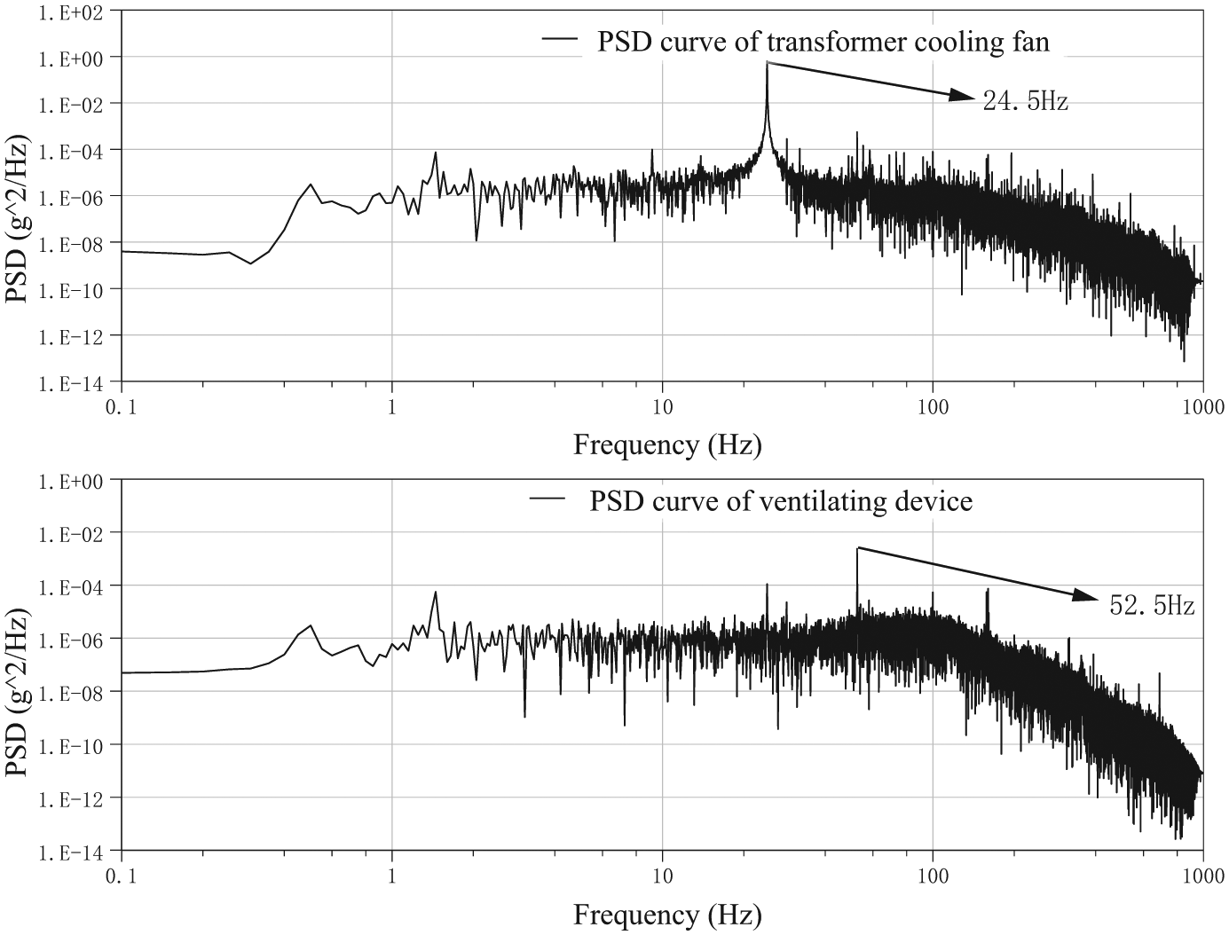
PSD curves of rotational equipment.

Field test result of carbody vertical vibration: (a) time domain analysis and (b) frequency domain analysis.
As shown in Figure 3, the field test was conducted when the vehicle was in a parked state and the rotational equipment was in an operational state. The vibration characteristic of the carbody above the equipment was monitored before and after cleaning. After cleaning, the dust on the blade of the rotational fan was supposed to have been removed entirely. Figure 3(a) shows the vibration character of the carbody above the rotational equipment. After cleaning, there is a reduction in the vibration amplitude of the carbody. However, the difference is not significant and it is also hard to judge whether regular cleaning is suitable for reducing carbody flexible vibration from analyzing only the time domain chart. Therefore, a frequency domain chart was obtained, as shown in Figure 3(b). Before cleaning, the main frequencies influencing the carbody vibration characteristics include 24.36, 28.71, 48.99, 52.46, and 99.96 Hz. The influence of 52.46 Hz, which is equal to the rotational frequency of the underframe equipment, is the most important excitation source. After cleaning, the main excitation frequencies remain unchanged. However, the vibration amplitude at different frequencies has decreased, especially at 52.46 Hz. Other vibration frequencies belong to other equipment. For example, the vibration frequency of 99.96 Hz belongs to the air conditioner with the rated speed of 6000 r/min, while 48.99 Hz the cooling fan of the traction motor with the rated speed of 2910 r/min.
Decreasing the rotational unbalanced mass can effectively reduce carbody flexible vibration, and regular cleaning is supposed to be useful to reduce carbody local vibration. However, it is hard to operate because of the limitation of maintenance time and installation site. To reduce carbody flexible vibration in the long-term service, there is a need to provide a theoretical basis for the design of carbody underframe suspended system with rotational equipment.
Theoretical analysis
Establishment of vertical vibration model
To study the influence of unbalanced vibration on carbody elastic vibration, a vertical mathematic model of carbody underframe suspended system is built, as shown in Figure 4. The carbody is modeled as an Euler–Bernoulli beam with three elastic freedoms and the equipment mounted on the chassis is regarded as a DVA.

Vertical mathematic model of carbody underframe suspended system.
In the model, the primary and secondary suspensions of vehicle system are equivalent to be the parallel spring–damping element, describing as (k1, c1) and (k2, c2). The rotational equipment with unbalanced vibration is suspended under the carbody underframe with the elastic element (ke, ce). When the vertical displacement of carbody is expressed as zc(x, t), the partial differential equation of the carbody underframe suspended system can be expressed as

where EI represents the flexural rigidity of carbody;


with zc, zb, and ze as the displacements of carbody, frame, and rotational equipment, respectively.
The unbalance centrifugal force is produced by the rotational equipment. And the vertical unbalanced force on the underframe equipment is

where m is the mass of rotor, e the eccentric distance to the rotation center, and w0 the angular velocity. Usually, me is described as the unbalanced mass.
The rigid modes of carbody include bounce and pitch motions (zc and θc), and the shape function can be described as Y1(x) = 1 and Y2(x) = x – L/2 in which L represents the length of beam. So, considering n flexible modes, the vertical displacement of carbody can be written as

where Yk(x) and qk(t) represent the shape function and modal coordinate of kth mode, respectively.
The general solution of the shape function is
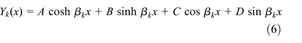
The flexible carbody is assumed to be the Euler beam with free boundaries; thus, the boundary conditions are taken as

Substitution of equation (7) into equation (6) gives the solution of the shape function

By substituting equation (5) into equation (1) in parallel with equations (2) and (3), one obtains


Also, the bounce and pitch equations of the underframe equipment can be expressed as


Considering the frame with the bounce and pitch movement and the wheelset with bounce freedom, the equations can be described as follows


where i = 1, a = 1, 2; i = 2, a = 3, 4. pa is the half contact force of ath wheelset and the rail (a = 1–4), which can be deterred by the Hertzian nonlinear elastic contact theory 19

In the equation, z0a is the input of wheel/rail displacement; G is the wheel/rail contact constant. To make the study convenient, zwa is assumed to be equal to z0a, then pa = 0.
Parameter studies
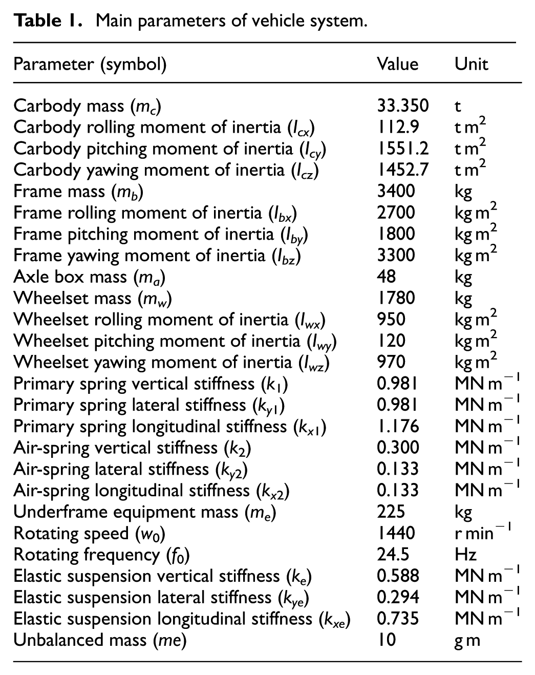
Referring to the suspension parameters of the vehicle system in Table 1, 21 the calculation of the mathematic model is made with random excitation measured from Wuhan–Guangzhou high-speed line. 22 Track irregularity acts on each wheel and the time delay is considered. Then the vertical vibration of carbody center and also the position above the rotational equipment can be obtained.
Main parameters of vehicle system.
In this section, the influence of suspension parameters of the underframe suspended system on carbody vibration characteristics is studied. For the convenience of the study, some parameters are defined

where fe is the suspended frequency,
Rotational unbalanced mass
The vibration performance of carbody underframe suspended system with unbalanced mass is shown in Figure 5. The simulation is conducted when the suspension frequency is 6 Hz and the location is 1 m. It is indicated from the calculation results that the vibration of carbody increases obviously with the increase of unbalanced mass. The vibration performance on carbody center is taken for example. The acceleration root mean square (RMS) value of carbody increases in parallel with the unbalanced mass increasing from 0 to 15 g m. It means that the influence of unbalanced mass on carbody vibration is certain, which is almost consistent at different speed levels.

Influence of unbalanced mass on carbody vibration.
When the vehicle running speed is 300 km/h, the RMS of carbody vibration acceleration with the increase of the unbalanced mass is 0.045, 0.052, 0.067, and 0.087 m/s2, respectively. It increases 0.933 times from 0 to 15 g m. With the unbalanced mass of 10 g m, the carbody vibration increases about 0.377 times from the running speed of 200–400 km/h, which is much smaller than the influence of the unbalanced mass. Thus, the conclusion can be made that unbalanced vibration of rotational equipment can be one of the main factors affecting carbody vibration and there is a need to conduct the thorough research and the discussion.
Suspension frequency
According to the theory of DVA, reasonable suspension parameters can effectively reduce the elastic vibration of carbody. Here, some parameters, such as the suspension frequency fe, the suspension damping ratio
The underframe equipment is suspended 1 m far from carbody center in the longitudinal distance. The suspension damping ratio is supposed to be 0.1. The effect of suspension frequency on carbody vertical vibration is described in Figure 6.

Influence of suspension frequency on carbody vibration: (a) suspension mode and (b) suspension frequency.
Figure 6 shows the influence of the rigid and the elastic connection on carbody vibration which shows that the elastic connection can reduce carbody vibration greatly. To carbody vibration with elastic connection, the vibration of the vehicle carbody decreases first and then increases with an increase of the suspension frequency. The minimum RMS acceleration of the carbody vertical vibration is obtained at 4 Hz. Under the running speed of 300 km/h, the minimum RMS value is 0.058 m/s2, while the maximum is 0.066 m/s2 with an increase of 13.7%. Actually, the vibration less than 4 Hz varies small and it can be concluded that the increased suspension frequency leads to more vibrational energy transfer due to rotational imbalance to the carbody. However, considering the theory of DVA, the suspension frequency should be within a reasonable range. It is indicated that both the theory of DVA and dynamic unbalance should be considered to optimize reasonable suspension parameters.
Suspension damping ratio
As shown in Figure 7, the influence of suspension damping ratio is analyzed. The simulation is conducted when the suspension frequency is 6 Hz and the location is 1 m. It can be seen that the influence on carbody vertical vibration is small. The variation law on carbody vibration of each suspension damping ratio is similar. Under the running speed of 300 km/h, the carbody vibration of the underframe suspended system under the suspension damping ratio 0.1 is smallest with the RMS value of 0.063 m/s2. Meanwhile, the carbody vibration under the other calculated damping ratio is about 0.065 m/s2. The difference among the damping ratio is little enough to even be ignored.

Influence of suspension damping ratio on carbody vibration.
Obviously, the influence of the suspension damping ratio on the carbody flexible vibration is less than that of the suspension frequency. As the suspension frequency and the damping ratio are the main properties of the rubber units, when it comes to the vibration of underframe suspended system, both of them should be discussed.
Suspension location
In this section, the influence of suspension location of underframe rotational equipment on carbody vertical vibration is discussed. The location varies from 0 to 5 m in the longitudinal distance from carbody center. The dynamic performance of carbody center is described in Figure 8.

Influence of suspension location on carbody vibration.
It can be seen from the figure that the suspension location affects carbody vertical vibration obviously. The changing law on carbody vibration of each suspension location is similar. And the minimum RMS acceleration of the carbody vertical vibration is obtained at 2 m. With the increase of the suspension location, the RMS value of carbody vibration decreases slowly and then increases rapidly. Under the running speed of 300 km/h, the minimum RMS value is 0.059 m/s2, while the maximum is 0.112 m/s2 with an increase of 89.8%.
When the location is larger than 3 m, carbody vibration increases greatly. It indicates from the analysis result that the underframe equipment with dynamic unbalance should be located within 3 m from carbody center to obtain good vertical vibration performance of carbody. The main reason is probably that carbody flexible vibration in 2 m is smaller than the others, which can be proved by the carbody shape function of equation (8).
Simulation analysis
Establishment of rigid–flexible coupled vehicle system
The theoretical model is an equivalent model, which has no direct relation with the actual geometric structure of the carbody, and the model is simplified without considering nonlinear factors, such as the wheel/rail contact relationship. However, in the design stage, only the theoretical model can be used well to get the preliminary parameters of the underframe suspended system. Meanwhile, the FE model is based on the three-dimensional structure of carbody, which can reflect the actual structural characteristics. The result of the FE model is much closer to the result of the modal test. Thus, a three-dimensional rigid–flexible coupled vehicle dynamic simulation model is needed.
The dynamic model of a high-speed EMU operated in China was built using the software package SIMPACK and ANSYS. To provide an acceptable carbody elastic model, the Guyan method 23 is used in model processing to obtain a carbody substructure model. Also, a model test of carbody was conducted to verify the carbody FE model. The carbody modal results of the complete model, and substructure model, the modal test is compared in Table 2. The frequency of the carbody modal results over 20Hz are not recognized because the excitation frequency is 0.5–20 Hz. Therefore, it can be indicated that the substructure model can be used for the establishment of the simulation model.
Vibration modal shapes and frequencies of operating carbody.
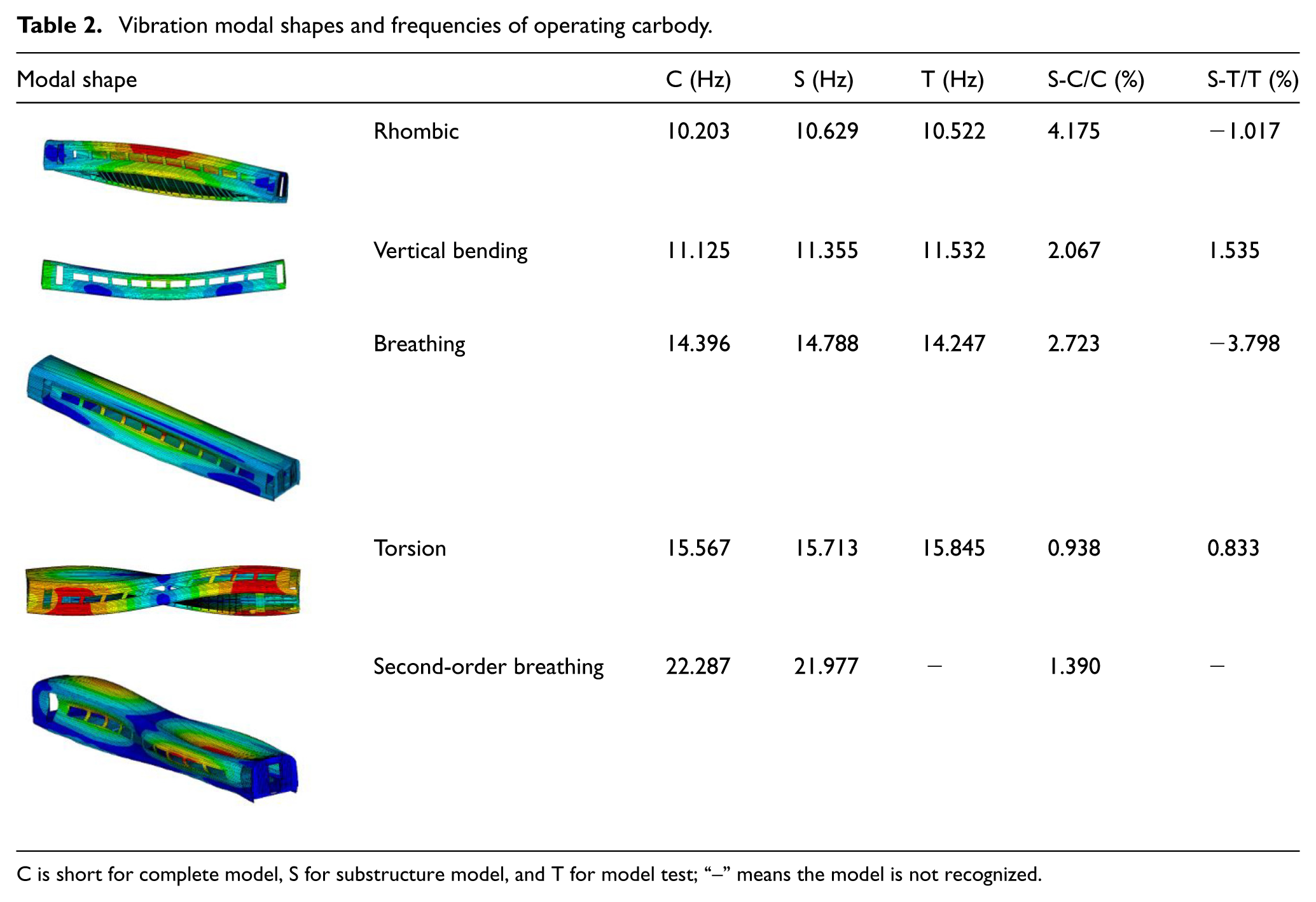
C is short for complete model, S for substructure model, and T for model test; “–” means the model is not recognized.
Figure 9 shows the rigid–flexible coupled model of a high-speed vehicle. The model includes one elastic carbody with one underframe rotational equipment, two bogie frames, and four wheelsets. The equipment only owns the bouncing motion, box guiding arms with only pitch movements, and others with each 6 degrees of freedom. Considering the nonlinear wheel/rail contact relation and suspension parameters, the kinetic equation of the vehicle system is as follows

where

Rigid–flexible coupled dynamic model of high-speed railway vehicle.
A cooling fan of traction transformer is used as an example to study the coupling vibration of the carbody and the underframe rotational equipment. The suspension frequency fe is 4 Hz and the damping ratio
Parameter studies
Influence of underframe equipment suspended modes
Both rigid and elastic connecting modes are adopted for the underframe suspended system of high-speed vehicles. Based on the simulation model, the impact of equipment suspended mode on carbody elastic vibration is studied with dynamic unbalance. Figure 10 shows the influence of the two connecting modes, rigid or elastic, on the vertical vibration of the carbody above the underframe rotational equipment. Both the time and frequency domains are analyzed under the operating speed of 300 km/h.

Carbody vertical vibration above the equipment: (a) time domain analysis and (b) frequency domain analysis.
As shown in Figure 10(a), the vertical vibration of the vehicle carbody with rigid connecting mode for the underframe suspended system is larger than that of elastic connection. With the elastic connection, the maximum vertical acceleration of the carbody floor above the rotational equipment is 0.73 m/s2, while the maximum vibration with rigid connection is 1.6 m/s2, which is more than two times that of the elastic connection. This indicates that the elastic connection can effectively reduce the flexible vibration of the carbody. The main reason is that the elastic suspension can hinder the transmission of vibration energy caused by the unbalanced vibration of the rotational equipment to the carbody, which is proven by Figure 10(b). The frequency domain analysis shows that the vertical vibration energy is mainly concentrated at about 24.5 Hz, which is just as the same as the natural frequency of the rotational equipment. Both of the main vibration frequencies of the carbody under two connecting modes are due to unbalanced vibration. The difference between the elastic and rigid connections lies in the reduction of the unbalanced vibration of the rotational equipment. However, at other frequencies, the difference between them is very small.
Rotational unbalanced mass
Figure 11(a) shows the relation between carbody vertical vibration above the rotational equipment and the unbalanced mass. When the vehicle running speed is 100 km/h, the vibration RMS value changes from 0.09 to 0.3 m/s2, with an increase of more than three times. At the speed of 300 km/h, the value increases from 0.17 to 0.33 m/s2, an increase of nearly two times. With the increase of the unbalanced vibration, the vibration of the carbody obviously deteriorates. The vibration increases slowly at first and then quickly. When the rotational imbalance is small, the difference in the carbody vibration is obvious for the operational speeds. With an increase of the rotational imbalance, the difference becomes small, which can indicate that the unbalanced vibration is gradually becoming the main source of carbody vibration.
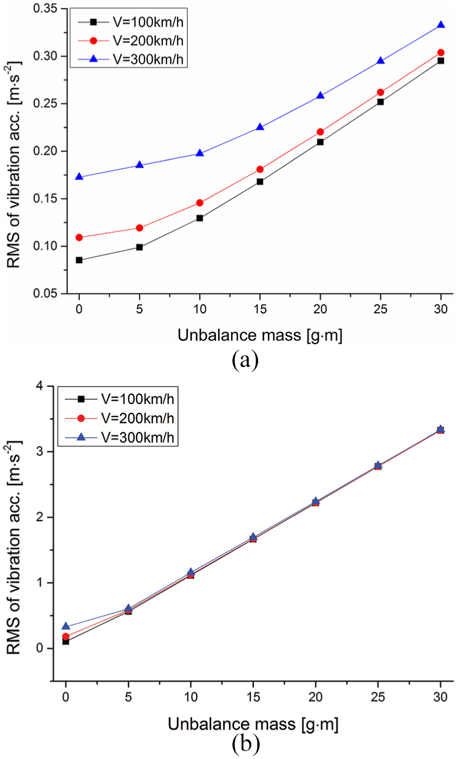
Influence of unbalanced mass on carbody underframe suspended system: (a) carbody vertical vibration and (b) underframe equipment vertical vibration.
Figure 11(b) shows that the vertical vibration of the suspended equipment is nearly proportional to the rotational imbalance, while the operational speed of the vehicle does not affect the vibration of the equipment. Only when the unbalanced mass equals to 0, the influence of the running speed on the underframe equipment will be reflected.
Model verification
The theoretical and simulation method are used to analyze the vibration performance of carbody underframe suspended system. To validate the model, another field test was conducted on a newly designed high-speed railway vehicle. And the vibration of the ventilating device, weighting 980 kg, was studied.
For railway used equipment, the unbalance mass of newly installed rotational equipment must be less than 4 g m, based on relevant standards. Due to the limitations of the field test conditions, the unbalance mass of the ventilating device could not be got. It is assumed to be 10 g m in the later analysis. The dominant frequency of the rotational equipment is 37.5 Hz.
The initial suspension stiffness of the rotational equipment is measured to be 5.853 MN/m, equivalent to the suspension frequency of 12.3 Hz. Based on the simulation model, the optimized suspension frequency is 7.1 Hz, equivalent to the suspension stiffness of 1.951 MN/m, defined as the final parameter. For the convenience of the study, carbody vibration above the suspended equipment was filtered with 35–40 Hz bandpass. The vibration performance under two suspension frequencies is compared under the speed of 300 km/h in Figure 12(a).

Time domain analysis of carbody vibration: (a) the simulation result and (b) the field test result.
It is indicated from Figure 12(a) that the application of the final parameter can isolate the dynamic unbalance effectively by a reduction of 71.2%. Based on the initial parameter and the final parameter (the suspension frequencies of 12.3 and 7.1 Hz, respectively), a field test is conducted when the vehicle speed was 300 km/h and the rotational equipment was in an operational state. The test results are shown in Figure 12(b).
The rotational frequency of the suspended equipment is 37.5 and the doubling frequency 75Hz. Thus, the carbody vibration is filtered separately with 35–40 and 70–80 Hz bandpass.
In the field test, carbody vibration caused by dynamic unbalance was aggravated under the initial parameter, while it can be weakened with the final parameter by a reduction of 65.7% on 35–40 Hz bandpass data. The complex of the vibration environment can be the main reason making the reduction effect decreased. Comparing the simulation and the field test results, the theoretical and the simulation model established in the paper is verified to be reasonable.
Conclusion
Carbody vibration caused by dynamic unbalance of underframe suspended equipment is discussed. Both field tests and simulation methods are used to analyze the coupling vibration of carbody and the suspended equipment. Parametric studies are also conducted for carbody vibration reduction. The results are summarized as follows:
The underframe suspended system of the high-speed railway train with dynamic unbalance was investigated. The field test results show that the rotational underframe equipment with dynamic unbalance does affect the flexible vibration of the carbody, which affects the passenger ride comfort and may also cause fatigue problems for the carbody structure.
A vertical mathematic model and a three-dimensional rigid–flexible coupled vehicle dynamic simulation model were established to study the mechanism of the underframe suspended system with dynamic unbalance. Another field test was conducted to verify the model, which shows a good agreement with the simulation.
It is seen from parametric studies that carbody flexible vibration can be reduced effectively by decreasing the unbalanced mass and selecting reasonable suspension parameters. Both the theory of DVA and dynamic unbalance should be considered to optimize reasonable suspension parameters.
Footnotes
Handling Editor: Davood Younesian
Declaration of conflicting interests
The author(s) declared no potential conflicts of interest with respect to the research, authorship, and/or publication of this article.
Funding
The author(s) disclosed receipt of the following financial support for the research, authorship, and/or publication of this article: This work was supported by the National Natural Science Foundation of China (no. U1334206), Science & Technology Development Project of China Railway Corporation (nos 2016J001-B and 2016G008-B), and National Key R & D Plan (no. 2016YFB1200505).