
Abstract
The comprehensive performance test of motorized spindle will contribute to improve the machining quality of machine tool. But existing standards for testing the performance of motorized spindle are limited to test its partial static and dynamic performances. Meantime, most of the researches only focus on the vibration, thermal deformation, and rotary accuracy of motorized spindle. Consequently, how to accurately and comprehensively test the performance of motorized spindle is the key problem. For solving this problem, a comprehensive testing technology is presented in this article. In detail, some principles for establishing a test index system are proposed. And, by synthetically and systematically analyzing the process of structural design, manufacturing and assembly, use, and service, an index system for characterizing the comprehensive performance of motorized spindle is built. Then, some operational test methods are provided to evaluate the selected indexes. Finally, the proposed technology is taken to test a motorized spindle. In brief, the proposed technology will make the performance test of motorized spindle more comprehensive and operational and can provide support for improving the comprehensive performance of the motorized spindle.
Introduction
As known, the motorized spindle is the combination of spindle and motor and has many advantages, such as small vibration, low noise, high accuracy, and high speed. Therefore, it has been widely applied in the field of ultra-precision machining. Correspondingly, its performances would directly affect the machining performance of computer numerical control (CNC) machine tool, 1 such as temperature, vibration, and precision. Therefore, its performance test has played an important role in the improvement of machine tool’s performance. And the test should cover most of the performances of motorized spindle, which means it should be comprehensive. For carrying out this test, it is of great significance to carry out researches about the measurement index system of motorized spindle and its test methods.
With the development of machine tool, more and more items are adopted to characterize the performance of CNC machine tools and spindle system. And their test methods have also appeared in some international standards, such as ASME2,3 and ISO.4–6 Meanwhile, the performance testing standard of motorized spindle has also been developed,7–10 such as JB/T 10801.2, JB/T 10801.3, ASME B89.3.4, and ISO/TR 17243-1. However, these standards only focus on tests about partial static and dynamic performances of motorized spindle, and tests about modal characteristics and service performances are not given. In addition, there are some researches about the comprehensive performance evaluation of motorized spindle. First, Zhou et al. 11 took five items to characterize the comprehensive performance of motorized spindle, such as temperature rise, thermal deformation, speed–load characteristics, geometric accuracy of axes of rotation, and dynamic and static characteristics. Then, Lin and Tu 12 offered a model-based design of motorized spindle systems to improve the dynamic performance at high speeds and identified eight parameters to represent the overall spindle design problems. Moreover, Jilin University tried to characterize the comprehensive performance of a motorized spindle by seven items, such as static stiffness, modal characteristics, vibration characteristics, noise, speed–load characteristics, geometric accuracy of axes of rotation, temperature rise, and thermal deformation.13,14 Simultaneously, Beijing University of Technology took the speed–load characteristics, geometric accuracy of axes of rotation, precision sustainability, static stiffness, and modal characteristics as comprehensive performance evaluation indexes of a motorized spindle.15,16
Simultaneously, test methods and devices of motorized spindle performance have also been rapidly developed, such as Spindle Analyzer from Automated Precision Inc. (API) and Spindle Error Analyzer from Lion Precision Inc. Both the devices have the ability to measure the geometric accuracy of axes of rotation, temperature rise, and thermal deformation. In addition, Jywe and Chen 17 proposed a non-contact method to measure the geometric accuracy of axes of rotation by a laser sensor and a phase-sensitive demodulator. However, this method cannot measure the tilt error and axial error of motorized spindle. Then, Yang et al. 18 took a ball-bar to measure the thermal deformation of motorized spindle, but this method must cooperate with a 2-degree-of-freedom (DOF) platform. And, motion errors of this platform would exist in measurement results of their method. Then, Bak and Jemielniak 19 developed a single-input, single-output (SISO) measurement system to test the modal characteristics of a motorized spindle, and this system was easy to be used by inspectors. Moreover, Chang and Chen 20 presented a spectral analysis technique to monitor the vibration of a motorized spindle, and this technique would record the condition of spindle rotation even under the condition of misoperation. In addition, Jilin University developed a test bench to evaluate the comprehensive performance of motorized spindles. This bench could test the reliability, precision sustainability, temperature rise, thermal deformation, speed–load characteristics, and geometric accuracy of axes of rotation of motorized spindle.13,14 Furthermore, Beijing University of Technology presented another test bench which testes the speed–load characteristics, static stiffness, modal characteristics, temperature, and geometric accuracy of axes of rotation of motorized spindle.15,16
From the above studies, it can be concluded that the existing index system cannot comprehensively represent the performance of motorized spindle, and the existing test system cannot evaluate all items existed in the test standard. Therefore, for checking the overall performance of motorized spindle, this article focuses on the following works.
First, establish some principles for building a test index system of motorized spindle. Second, build an index system for characterizing the comprehensive performance of motorized spindle by systematically analyzing the structural design, manufacturing and assembly, use, service, and test standards of motorized spindle. Third, develop operational test methods of selected indexes for comprehensively checking the performance of motorized spindle. Fourth, the proposed technology is taken to test a motorized spindle.
Index system for comprehensive performance test of motorized spindle
Construction principles of index system
The index system is designed to comprehensively characterize the performance of motorized spindle. Simultaneously, its scientificity and rationality will directly affect the credibility and accuracy of the comprehensive performance evaluation result of a motorized spindle. Consequently, the index system must be scientific, objective, reasonable, and comprehensive. And, it must be established on some specific principles which are given as follows:
Principle of comprehensiveness. Minutely, the index system should comprehensively characterize the performance of motorized spindle in the process of structural design, manufacturing and assembly, use, and service.
Principle of independence. In detail, each index should be independent, and an index should generalize one of the motorized spindle’s performances.
Principle of measurability. In detail, every index in the index system can be tested based on its relevant measurement theory.
Principle of clarity. In detail, every index in the index system could accurately characterize one of the motorized spindle’s performances.
Establishment of index system
A typical structure of motorized spindle is shown in Figure 1. As shown in the figure, the motorized spindle is mainly composed of spindle shaft, stator winding, rotor winding, bearing, housing, broaching mechanism, cooling and lubricating mechanism, and so on. According to the principle of comprehensiveness, the index system should comprehensively characterize the performance of motorized spindle in the process of structural design, manufacturing and assembly, use, and service:
From the aspect of structural design, unreasonable structure of spindle shaft and its attachments will increase the imbalance of spindle shaft which worsens the vibration and machining accuracy of motorized spindle and increases its temperature. Simultaneously, unreasonable structure of spindle also will enlarge the thermal deformation.
In the case of manufacturing and assembly, the manufacturing precision of spindle shaft and the connection type between the shaft and its attachments will affect the imbalance of motorized spindle.
In the case of use, the dynamic performance, thermal deformation, load-bearing capacity, and imbalance will affect the machining quality of motorized spindle. 21
From the aspect of service, the reliability and precision sustainability almost decide the maintenance of a spindle.

Typical structure of motorized spindle.
Simultaneously, by analyzing the performance test standard of motorized spindle (i.e. JB/T 10801.2, JB/T 10801.3, ASME B89.3.4, and ISO/TR 17243)7–10 and consulting the international standards about machine tool, an index system, shown in Table 1, is established for characterizing the comprehensive performance of motorized spindles based on the proposed principles. As shown in Table 1, the proposed index system provides specific items to reflect the performance of motorized spindle. Meantime, every item can clearly characterize one of the performances of motorized spindle. In addition, this system also provides specific sub-items to characterize one of the selected items, which makes selected items measurable.
Index system for characterizing comprehensive performance of motorized spindle.
Safety performance
Safety performance mainly checks the factor that may cause damage to motorized spindles or operators in the process of handling and using of motorized spindle, and it consists of mechanical safety and electrical safety. In detail, the aim of mechanical safety is to check the measure used to prevent the motorized spindle or operator from being mechanically hurt, and electrical safety checks the ability to prevent the motorized spindle and operator from being hurt by electricity. Accordingly, its sub-items include insulation resistance, turn-to-turn insulation, and withstand voltage of winding.
Manufacturing and assembly
The aim of manufacturing and assembly is to evaluate the factor that affects the use of motorized spindle and exists in the manufacturing and assembling process of motorized spindle. Meanwhile, its items include coil-out and markers, materials and heat treatment, taper hole, sealing characteristics, and matching surface for installation.
Parameters and attachments
The aim of parameters and attachments is to evaluate the factor that affects the load capacity of motorized spindle, and its items include duty type, maximum speed, rated speed, rated voltage, and rated output power.
Performance requirement
The aim of performance requirement is to test the resistance to temperature rise, vibration, and cutting force in the working state of motorized spindle. And its sub-items or items include maximum output torque, broach force, absolute vibration, sound pressure level, axial stiffness, and radial stiffness.
Operation performance
The aim of operation performance is to mainly check the function and operation of motorized spindles, and it is composed of the functional normality test and operational stability test. In detail, the former checks whether functions of the motorized spindle, given by its standards, are normal, such as the tool release, broach, stop, start, and medium hole blowing, and the latter checks the stability of motorized spindle’s revolution.
Accuracy performance
The aim of accuracy performance is to test the geometric accuracy of motorized spindle that affects the machining quality of motorized spindle. Moreover, its sub-items include radial run-out, axial shift, and end-face run-out.
Dynamic performance
The aim of dynamic performance is to evaluate the performance of motorized spindle in its operating state. And its items include geometric accuracy of axes of rotation, thermal effects, dynamic balance, modal characteristics, and speed–load characteristics.22,23
Service performance
The aim of service performance is to evaluate the ability to maintain the performance of motorized spindle under given working conditions, and its items include reliability, precision sustainability, and lifetime. Among them, reliability represents the ability to perform a required function under stated conditions for a specified period of time, and the precision sustainability represents the ability to resist the degradation of accuracy performance under stated conditions.
Test methods of indexes
To a certain extent, all items may affect whether the motorized spindle works normally or not. However, measurement methods of some items (such as mechanical safety, parameters and attachments, operation performance, accuracy performance, and noise) are simple and could be finished by referring to JB/T 10801.2 and JB/T 10801.3, so this article just introduces the other items which are not very clear in the above-mentioned standards and need some complex testing devices. Details are given in the following sections.
Electrical safety test
Turn-to-turn insulation test
Turn-to-turn insulation represents the inter-turn insulation performance of motorized spindle. And the aim of turn-to-turn insulation test is to check the motorized spindle’s ability to resist breakdown of windings under a given voltage. In this article, this test is finished by the digital pulse coil tester UC5815-S4, and its test procedure is given as follows:
Select a winding to be tested.
Add a high-voltage narrow pulse at both ends of the winding. The high-voltage narrow pulse is defined by the parameters such as peak-to-peak voltage, wavefront time, test time, output method of test voltage, and the number of tests defined in JB/T 10801.27 and JB/T 10801.3. 8
Record the oscillating waveform of winding voltage.
Analyze the difference between the recorded oscillating waveform and its standard waveforms given by the measurement device. Simultaneously, the difference is evaluated by the parameters such as amplitude of waveform, cycle of vibration, area difference of waveform, and area of waveform difference.
Insulation resistance test
The insulation resistance characterizes the insulation performance between the stator windings or a stator winding and the housing. As known, the multifunctional portable test instrument MI 3321 MultiServicerXA can be applied to measure the insulation resistance, and its measurement system is shown in Figure 2.

Measurement system of insulation resistance.
Withstand voltage test of winding
The withstand voltage of winding shows the insulation performance between the stator winding and the housing. Meantime, the withstand voltage test of windings is used to check the motorized spindle’s ability to withstand a voltage for 1 min, and the voltage is given by JB/T 10801.2 and JB/T 10801.3. In this article, a DC withstanding voltage/insulation resistance tester, shown in Figure 3, is taken to measure the withstand voltage of motorized spindle’s winding.

Measurement system of withstand voltage of winding.
The corresponding test procedure is shown as follows:
Apply a test voltage between the housing and the end of winding. In detail, the voltage is a sinusoidal waveform with duration of 1 min and frequency of 50 Hz. And the root mean square (RMS) of this voltage must comply with the requirement of the above standards.
Measure the leakage current between a stator winding and the housing. Meantime, the measurement results should be less than the maximum leakage current defined in the standards.
Vibration and modal characteristic test
As known, higher the designed speed of a motorized spindle, the more obvious the effect of its dynamic characteristics on the machining accuracy of machine tool. When the dynamic characteristics of motorized spindle are unreasonable, the phenomenon of resonance or chatter will easily occur under the excitation of external or internal vibration. Simultaneously, this phenomenon will worsen the performance of machine tools, and even destroy machine tools. According to ISO 230-8, the vibration test and modal characteristic analysis of machine tool should be done. Because the motorized spindle is one of the key parts of the machine tool, its vibration test and modal characteristic analysis should also be done.
Vibration test
The absolute vibration of a motorized spindle is represented by RMS of vibration velocity of its housing and is defined by equation (1)

where vmax and vmin represent the maximum and minimum of vibration velocity, respectively.
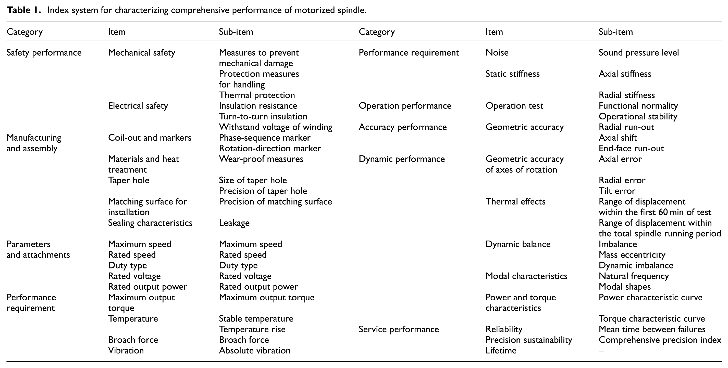
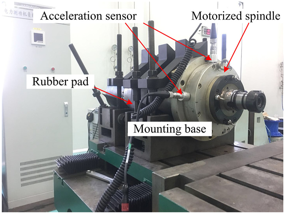
For achieving the absolute vibration of a motorized spindle, its testing conditions should be in accordance with its actual working state, and the sensor should be mounted in the axial and radial direction of motorized spindle. In addition, a double-channel vibration tester, shown in Figure 4, is used to test the absolute vibration of motorized spindles. Meanwhile, installation positions of sensors are depicted by Figure 5. In detail, positions X1, Y1, and Z1 represent the radial-vertical, radial-horizontal, and axial positions of the motorized spindle at the installation position of front bearing, respectively, and positions X2, Y2, and Z2 represent the radial-vertical, radial-horizontal, and axial positions of the motorized spindle at that of rear bearing, respectively. In addition, for measuring absolute vibration accurately, the vibration level of mounting base should be obviously smaller than that of the motorized spindle. Simultaneously, some rubber pads, whose thickness is generally 5–10mm,7,8 should be placed between the motorized spindle and the installation base.
Measurement system of absolute vibration.

Installation position of acceleration sensor.
The test procedure of absolute vibration is given as follows:
Measure the vibration velocity of the motorized spindle at selected speeds and install the acceleration sensor on the given positions (i.e. X1, Y1, Z1, X2, Y2, and Z2) as shown in Figure 5. In addition, the speed of motorized spindle should be set in turn from low to high, but less than its maximum speed.
Evaluate the RMS of the measured vibration velocity using equation (1).
Test method of modal characteristics
Because of the limitations of motorized spindle’s structure, a SISO measurement method is adopted to test the modal characteristics of motorized spindle, and its measurement system is given in Figure 6. As shown in the figure, this system has an acceleration sensor, a force hammer, a data acquisition system, and a PC. The force hammer is used to strike the motorized spindle and measure its force f(t), and the acceleration sensor measures the corresponding response x(t). Then, a fast Fourier transform (FFT) method is used to get the input spectrum F(f) and the output spectrum X(f) from f(t) and x(t), respectively. Finally, the frequency response function H(f) of motorized spindle can be obtained by equation (2)

When H(f) is achieved, the natural frequency of spindle can be solved by the graphical method provided by Bak and Jemielniak 19

Measurement system of modal characteristics.
Static stiffness test
In order to ensure machining quality, machine tools must have high stiffness. But the static stiffness of motorized spindle is an important factor affecting the cutting stiffness of machine tools. As known, the stiffness is the ratio of the force to the displacement caused by this force. Consequently, the static stiffness of motorized spindle can be expressed by equation (3)

where F represents force (N) and d represents the change in displacement (μm). Based on equation (3), this article develops a measurement system for testing the static stiffness which is shown in Figure 7. The system is composed of a TT80 inductance micrometer, a force sensor, a cylinder, and its pneumatic loading system. While the pneumatic loading system exerts a force on the end of spindle shaft, the force sensor and inductance micrometer will record the force and displacement. Then, using equation (3), the static stiffness of motorized spindle can be measured.

Measurement system of motorized spindle’s static stiffness: (a) radial stiffness test and (b) axial stiffness test.
The corresponding test procedure is given as follows:
Install the motorized spindle on the test bed. The stiffness of the test bed should be obviously higher than the axial and radial stiffness of the motorized spindle.
Install the cylinder along the axial or radial direction of the motorized spindle. In detail, in case of radial stiffness measurement, the force point on spindle shaft should be as close as possible to its end face. And in case of axial stiffness measurement, the force point should be as close as possible to the axis of spindle shaft.
Mount the inductance micrometer along the axial or radial direction of the motorized spindle. In detail, in case of radial stiffness measurement, the measurement point of inductance micrometer and the force point of cylinder should be symmetrical to the axis of the spindle shaft.
Record the force and displacement using the force sensor and the inductance micrometer, respectively.
Evaluate the axial and radial stiffness of the motorized spindle using equation (3).
Geometric accuracy test of axes of rotation
The geometric accuracy of axes of rotation is a key index for evaluating the performance and quality of motorized spindle. Meantime, in the view of motion, motion errors of a motorized spindle include the axial error, radial error, tilt error, and indexing error. But the indexing error can be ignored. 11 In the view of frequency, there are synchronous error and asynchronous error existing in one of the motion errors which are shown in Figure 8. 24

Definition of synchronous error and asynchronous error.
In this article, the geometric accuracy of axes of rotation is measured by a Spindle Analyzer whose measurement principle is given in Figure 9. This Spindle Analyzer’s measurement method about the geometric accuracy of axes of rotation is designed based on the ISO230-7 standard. 5 In detail, five displacement sensors of Spindle Analyzer are used to measure the geometric accuracy of axes of rotation, and their installation positions are given in Figure 10, where X1, X2, Y1, Y2, and Z represent the positions of five displacement sensors. In addition, this system is established on a reference axis which is only a tool.

Measurement principle of the Spindle Analyzer.
Measurement system of geometric accuracy of axes of rotation.
In detail, the test procedure of geometric accuracy of axes of rotation is given as follows:
Install the motorized spindle on the test bed correctly and mount the displacement sensors based on Figure 10.
Preheat the motorized spindle by making it run for a certain time.
Make the motorized spindle work in test conditions which are defined by ISO 230-7. 5
Record the change in displacement and evaluate the axial error, radial error, and tilt error by the method given in ISO 230-7. 5
Evaluate the synchronous error and the asynchronous error existing in the axial error, radial error, and tilt error by the method given in ISO 230-7. 5
Temperature rise and thermal deformation test
As known, the heat produced by windings and bearings will cause the thermal deformation of motorized spindle, which would make the actual axis of spindle shaft deviate from its ideal position. This error has been reported to be about 70% of the total positioning error of the machine tool. 11
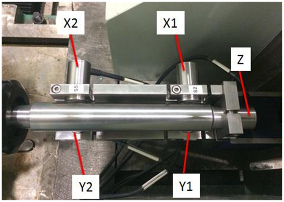
In this article, temperature rise and thermal deformation of motorized spindle are measured by the Spindle Analyzer whose measurement method about thermal deformation test is designed based on ISO 230-3. 4 Because the thermal deformation will result in two axial errors, two tilt errors, and one radial error, its measurement principle is same as the principle given in Figure 9. In addition, for measuring the temperature rise, six temperature sensors will be used. In detail, one of the temperature sensors is taken to measure the environmental temperature, and the rest are used to record the temperature of the spindle. Accordingly, the measurement system of temperature rise and thermal deformation can be expressed by Figures 10 and 11, where T1, T2, T3, T4, and T5 represent the positions of five temperature sensors.
Installation positions of temperature sensors.
The test procedure of thermal deformation and temperature rise is given as follow:
Install the motorized spindle on the test bed correctly. And mount temperature sensors, displacement sensors, and reference axis according to Figures 10 and 11.
Set the temperature of coolant of motorized spindle and make this spindle work at selected speed.
Record the range of displacement in the direction of X-axis at positions P1 and P2 within the first 60 min of the test (i.e. dx1,60 and dx2,60), record the range of displacement in the direction of Y-axis at positions P1 and P2 within the first 60 min of test (i.e. dy1,60 and dy2,60), record the range of displacement in the direction of Z-axis within the first 60 min of the test (i.e. dz,60), and record the range of angle in the direction of A, B axis at positions P1 and P2 within the first 60 min of the test (i.e. dA,60 and dB,60).
Record the range of displacement in the direction of X-axis at positions P1 and P2 within the total spindle running period t (i.e. dx1,t and dx2,t), record the range of displacement in the direction of Y-axis at positions P1 and P2 within the total spindle running period (i.e. dy1, t and dy2, t), record the range of displacement in the direction of Z-axis within the total spindle running period (i.e. dz, t ), and record the range of angle in the direction of A, B axis at positions within the total spindle running period (i.e. dA, t and dB, t ).
Record the temperature of motorized spindle and calculate the difference between the stable temperature of the spindle and the environmental temperature.
Dynamic balance test
Because of non-uniform material, asymmetrical structure, and machining and assembly error, the actual axis of the spindle shaft will deviate from its ideal position, which causes the imbalance of spindle shaft and results in its vibration. Simultaneously, this problem will be worsened with an increase in the spindle speed. Consequently, the dynamic balance test is vital to analyze the dynamic performance of the motorized spindle and will provide support for improving the dynamic unbalance of a motorized spindle.
In this article, an online dynamic balancing instrument, whose type is CB-8801, is taken to measure the dynamic balance of motorized spindle. It can measure single- or double-face imbalances. But in this article, the single-face measurement method is adopted, and its measurement system is shown in Figure 12. And, the corresponding measurement procedure is given as follows:
Mount two acceleration sensors on the installation positions of the front and rear bearings and install the speed sensor at the front of the motorized spindle.
Set the working speed of the motorized spindle, and start it.
Measure the amplitude A0 and phase α0 of the selected spindle’s vibration displacement.
Add a balancing mass G on the circumference of radius r, and its installation angle on this circumference is β.
Measure the amplitude A1 and phase α1 of the selected spindle’s vibration displacement.
Evaluate the imbalance of the selected spindle using equation (4)

where parameters K1 and K2 are defined by equations (5) and (6), respectively


Measurement scheme of motorized spindle’s dynamic balance.
Speed–load characteristic test
Since a motorized spindle is the combination of spindle and motor, it has the speed–load characteristics of motor which is usually represented by the power and torque characteristics.
As known, the power and torque characteristics of the motorized spindle can be determined by loading 0.25–1.25 times of the motorized spindle’s rated output power. 11 And this power can be provided by some loading devices such as the electric eddy current dynamometer and electric dynamometer. Therefore, this article designs a test system (shown in Figure 13) for determining the power and torque characteristics by taking an electric dynamometer for loading and provides a torque sensor and a speed sensor to measure the output torque and power of the motorized spindle at a given speed. In addition, the maximum speed and output torque of the power dynamometer are 12,000 r/min and 50 Nm, respectively.
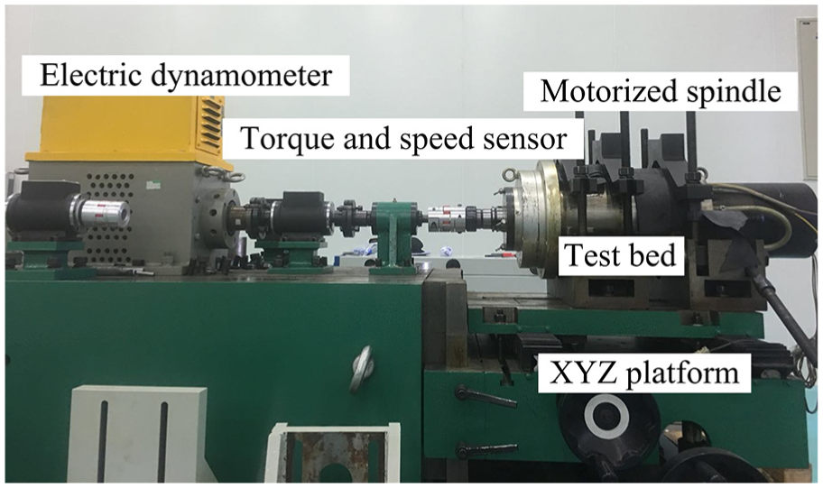
Test system of speed–load characteristics of motorized spindle.
The corresponding test procedure is given as follows:
Install the motorized spindle on the test bed and adjust its position with respect to the power dynamometer by the XYZ platform for making their concentricity less than 0.02 mm.
Start the test system and make the motorized spindle work at a stable speed. In addition, the speed of motorized spindle should be set in turn from low to high, but less than its maximum speed.
Slowly increase the output of the power of the electric dynamometer. Until the speed declines rapidly, stop increasing the power and record the actual speed and torque.
Get the values of motorized spindle’s actual speeds and output torques at every speed. Then, draw the power and torque characteristic curves of the motorized spindle which are shown in Figure 14.

Power and torque characteristic curves.
Reliability test
The reliability represents the ability to perform a required function under stated conditions for a specified period of time, and it is an important index to evaluate the service performance of motorized spindle. Simultaneously, the reliability bench test is one of the effective methods to evaluate the reliability of motorized spindle in the laboratory.
For evaluating the reliability of motorized spindle accurately, the test system should be able to simulate the actual working condition of motorized spindle. Consequently, Jilin University, based on this analysis, has developed a test system13,14,25 to evaluate the reliability of motorized spindle, and the system is shown in Figure 15. 25 According to the figure, the actual radial and axial forces of motorized spindle are simulated by two sets of electro-hydraulic servo loading systems, and the actual torque is simulated by a power dynamometer.
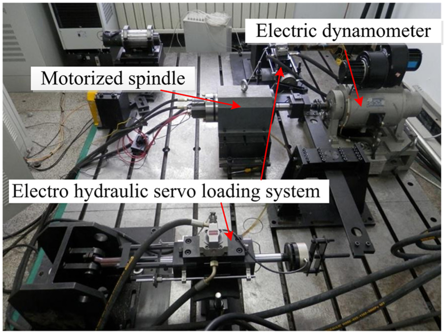
Reliability test system of motorized spindle.
The test procedure of reliability is given as follows:
Install the motorized spindle, select a load spectrum of motorized spindle which includes dynamic characteristics of actual radial force, axial force, and torque of this motorized spindle, and determine the test time T of reliability where T is usually 3 times of mean time between failures (MTBF) of this motorized spindle.
Start this test. And when the motorized spindle fails, record its fault information which is composed of the location of fault, phenomenon of fault, cause of failure, occurrence time of failure, and repair time of failure.
Remove non-associated faults of spindle from collected faults.
Let us suppose that the number of remaining faults is n + 1. Then, the observation of MTBF can be calculated by the following equation

where ti represents the time interval between the ith fault and the i + 1th fault.
In addition, the test system of reliability can be used to evaluate the precision sustainability of a motorized spindle.
Application
Test sequence
The test sequence should be set according to the following principles: First, it should avoid causing damage to the inspector; second, avoid causing tremendous damage to the motorized spindle; and finally, ensure that tests can be completed efficiently and accurately. Therefore, this article recommends the following test sequence for comprehensive performance test of motorized spindle:
Manufacturing and assembly test;
Safety performances test;
Parameters and attachments test;
Operation performance test;
Performance requirement test;
Accuracy performance test;
Dynamic performance test;
Service performance test;
Repeat tests 1–7.
However, the final test sequence should be set up in consultation with requirements of customers.
Test results
Because there are many testing items, this article only introduces some items which are depicted in section “Test methods of indexes.” And the details are shown in the following sections.
Vibration test
The test setting of the selected spindle is given in the sub-section “Vibration test” of section “Test methods of indexes,” and the test speeds of this spindle are 1000, 2000, 3000, 4000, and 5000 r/min. Meantime, the RMSs of vibration velocity of its housing at positions X1, Y1, Z1, X2, Y2, and Z2 are given in Table 2.
Results of vibration test (mm/s).

As given in Table 2, an increase in the vibration velocity of this spindle with its speed is achieved, and the vibration level of motorized spindle in the X-direction is more than that in other directions.
Modal characteristic test
In this section, the setting of modal characteristic test is based on the sub-section “Test method of modal characteristics” of section “Test methods of indexes.” Because the test methods of radial and axial modal characteristics are identical, this article just gives results about the radial modal characteristics which are shown in Figure 16. Meanwhile, based on the graphical method, 19 we can know that the first and second natural frequencies of the motorized spindle in the radial direction are 446.9 and 640.9 Hz, respectively.
Test result of modal characteristics at the radial direction of the selected spindle.
Static stiffness test
In this section, the radial and axial static stiffness of the given spindle are measured. Simultaneously, this test is based on the sub-section “Static stiffness test” of section “Test methods of indexes.” Correspondingly, its results are given in Table 3, where the unit of F, d, and K are N, μm, and N/μm, respectively. As shown in Table 3, the radial and axial static stiffness are 51.7 and 63.3 N/μm, respectively.
Test results of static stiffness.

Geometric accuracy test of axes of rotation
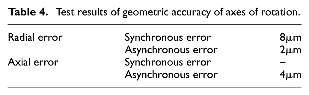
In this section, the geometric accuracy test of axes of rotation of the selected spindle at 800 r/min is measured, and its test setting is coincident with the sub-section “Geometric accuracy test of axes of rotation” of section “Test methods of indexes.” For simplifying this test, this article just measures the axial and radial errors. And the corresponding result curve is given in Figure 17. Meantime, the synchronous and asynchronous errors of the axial and radial errors are given in Table 4. As shown in the table, the position of PC coincides with that of minimum radial separation center (MRS) which means the reference axis almost coincides with the axis of this spindle, and the test results almost represent the geometric accuracy of axes of rotation of this spindle.
Test results of geometric accuracy of axes of rotation.

Result curve of the radial error of the selected spindle.
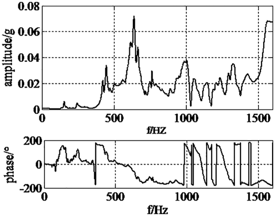
Temperature rise and thermal deformation test
In this section, the test method, shown in the sub-section “Temperature rise and thermal deformation test” of section “Test methods of indexes”, is taken. The radial errors, axial errors, and tilt errors, measured from the Spindle Analyzer, are shown in Figure 18(a) and (b), and their test results are given in Table 5. Meantime, the test results of temperature at positions T1, T2, T3, T4, and T5 are depicted in Figure 18(c).
Evaluation result of thermal deformation test.
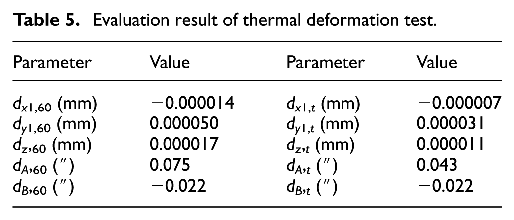
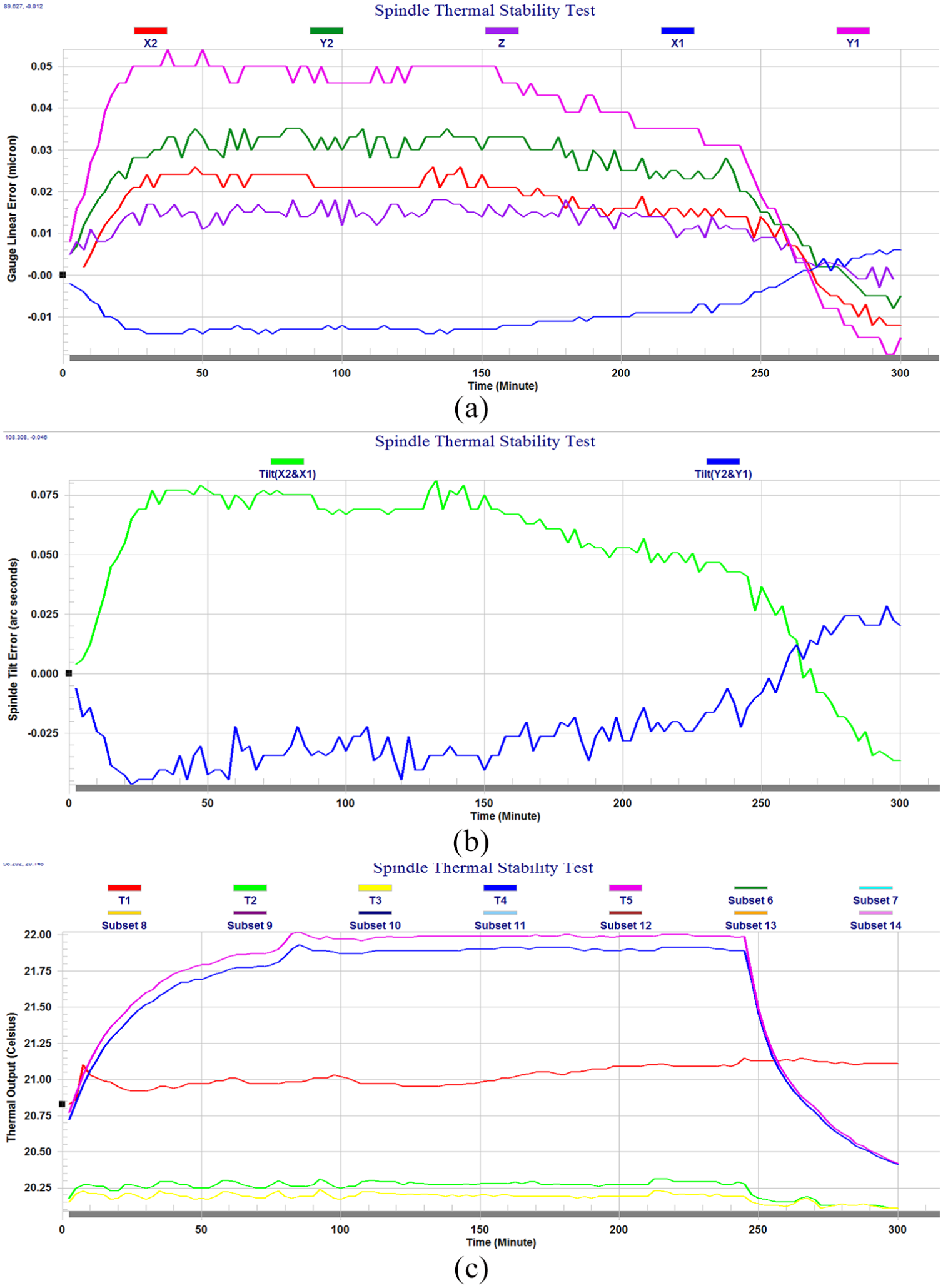
Test results of temperature rise and thermal deformation: (a) test results of radial and axial errors caused by thermal deformation; (b) test result of tilt errors caused by thermal deformation; and (c) test results of temperature at positions T1, T2, T3, T4, and T5.
As depicted in Figure 18, the thermal deformation and temperature of the selected spindle tend to be stable after 30 min which means that the results in Table 5 are reasonable and stable. In addition, as shown in Table 5, we can know that the maximal radial error caused by thermal deformation is less than 0.00005 μm, maximal axial error is less than 0.000017 μm, and maximal tilt error is less than 0.075″.
Dynamic balance test
In this section, the test method of dynamic balance, depicted in the sub-section “Dynamic balance test” of section “Test methods of indexes,” is taken. Meanwhile, the test speed of this spindle is 900 r/min. Accordingly, its test data are given in Table 6. Based on the table and equation (4), the imbalance of the selected spindle can be evaluated, and its value is 5.27 g·mm.
Test data of selected spindle’s dynamic balance.

Conclusion
This article provides a comprehensive performance testing technology for motorized spindle. And the technology includes an index system and test methods, which makes the performance test of motorized spindle more comprehensive and operational. In addition, the following observations are made:
By analyzing the process of motorized spindle’s structural design, manufacturing and assembly, use, and service, and based on the construction principle of index system, an index system is built for synthetically and systematically characterizing the performance of the motorized spindle. This system almost covers the static and dynamic performances of the motorized spindle and can more completely characterize the comprehensive performance of the motorized spindle.
Test methods of some indexes, such as electrical safety, vibration, modal characteristics, static stiffness, geometric accuracy of axes of rotation, temperature rise, thermal deformation, dynamic balance, speed–load characteristics, and reliability, are provided. They are more operational and easily adaptable to most types of the spindle.
This article proposed a test sequence of motorized spindle. And this sequence can partly avoid causing damage to the inspector and motorized spindle and ensure the effectiveness and accuracy of the test.
Finally, it is important to note again that our results can be used to comprehensively check the performance of a motorized spindle. However, the performance testing systems of the motorized spindle are not integrated as a system. Consequently, further work about the integration of test systems should be taken.
Footnotes
Handling Editor: Zengtao Chen
Declaration of conflicting interests
The author(s) declared no potential conflicts of interest with respect to the research, authorship, and/or publication of this article.
Funding
The author(s) disclosed receipt of the following financial support for the research, authorship, and/or publication of this article: This research was supported by the National Science and Technology Major Project (no. 2016ZX04004007).