
Abstract
This work provides a comprehensive review of numerical simulation and optimisation of the shot peening found in the existing literature over the past 10 years. The review found that the developed numerical models coupling finite elements with discrete elements became increasingly mature and showed their advantages in incorporating flow behaviour and randomness of shots. High emphasis must be placed on the constitutive equations of target material where its strain-rate sensitivity, cyclic behaviour and Bauschinger effects are recommended to be incorporated in the numerical material model simultaneously since considering one of them in isolation may lead to unreliable distribution of residual stresses. Furthermore, material hardening is a critical benefit of shot peening; however, it has not received its deserved attention from the existing investigations, neither in simulation nor in optimisation. The study found that intensity and coverage are two critical control parameters recommended to be constraints for optimisation of shot peening. Finally, this work also found that developed heuristic algorithms, such as genetic algorithms have recently showed their advantages for searching optimal combinations of peening parameters. It is plausible that in the near future, the synergy of combining these algorithms with approximation models can be expected to gain more attention by researchers.
Introduction
Shot peening (SP), as a surface treatment process, is frequently used to enhance the fatigue life of metallic components1,2 in the manufacturing industry, since it produces compressive residual stresses (CRSs) on the peened surface to delay initiation of fatigue failure and retard its propagation. 3 On the contrary, this surface treatment also induces surface roughness and causes cold working of the peened component. 3 These two effects are detrimental to the fatigue life of the component. Furthermore, the SP process is influenced by several continuous and discrete parameters 4 which have deterministic influences on its effectiveness. 5 Among some of these parameters, interactions exist between each other. 6 Most importantly, its potential to enhance fatigue life of components depends on the reasonable application of these influential parameters.1,7 In other words, inappropriately specifying these influential parameters could reduce the benefits of CRS induced by SP. Since SP has many influential parameters, and produces both detrimental and beneficial effects, many investigations have been conducted to study this surface treatment process. These investigations include examining the material behaviour of its target components, 8 adjusting its influential parameters,9,10 controlling its detrimental effects11,12 and simultaneously enhancing the beneficial effects arising from the induced CRS. In addition, compared to physical experimentation, numerical methods were increasingly used since it is time-saving and economical. As research into SP attracts increasing attention, it is crucial to provide a global insight into this field by reviewing the relevant literature. Hence, this article provides an extensive and critical review of the available literature on both numerical simulation and optimisation of SP in the past 10 years or so.
SP and its influential parameters
SP
SP is a cold working process and a surface finish treatment often applied to improving the fatigue life of metallic components 13 in the aero, 14 power generation, automotive and biomedical industries. 3 It is essentially a process where one solid sphere impacts another solid surface, 15 as shown in Figure 1. During this process, the target deforms leading to compression in its surface layer. The process of the deformation and the compression of the target material are illustrated as follows.
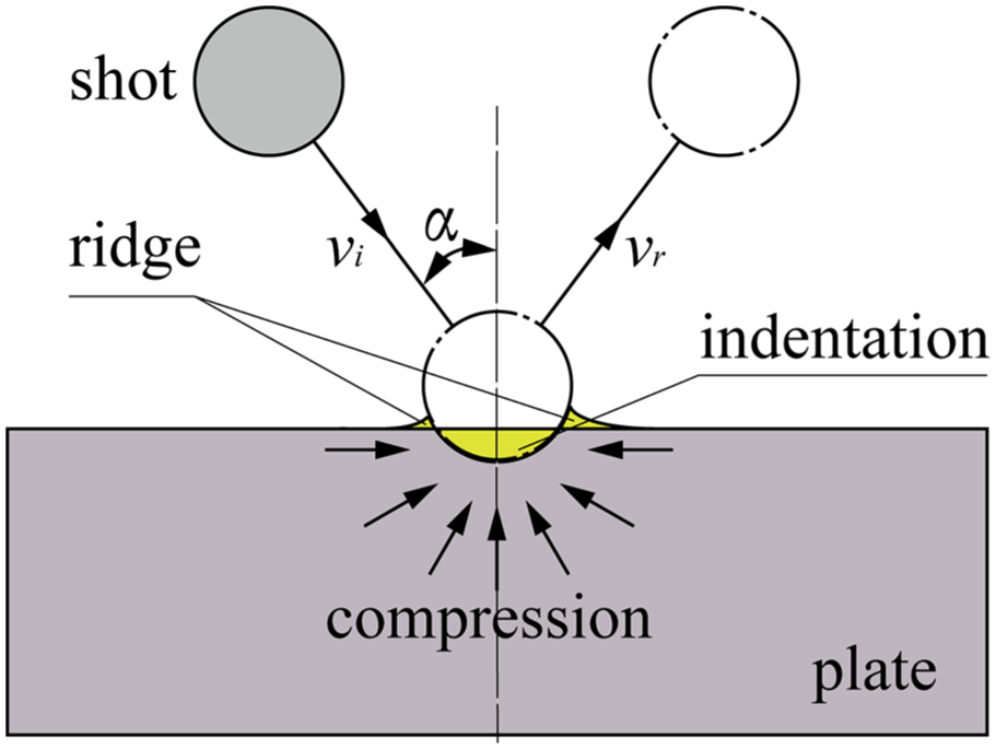
Schematic diagram of formation of CRS. The shot moves at a constant velocity,
During the SP process, the shot strikes the target (plate surface) acting as a tiny peening hammer, which forces the material of the plate at the impact centre to flow away. Some flow patterns create space for the newly formed indentation, while the other flow patterns form a ridge around the indentation. The indentation and the surrounding ridge are the two components of an impact. 16 Simultaneously, as the material flows away, the surface layer yields in tension due to the creation of the indentations, while the material below the surface layer tries to restore its original shape. Subsequently, a layer highly stressed in compression is produced 16 exhibiting CRS.
Influential parameters and responses to SP
SP is determined by many influential parameters which can be classified into three groups, namely, peening medium, peening device and workpiece.17,18 Figure 2 depicts these three groups and the corresponding SP products, namely, residual stress, surface roughness and material hardening. In line with the significance of their influences, only the main parameters, such as radius of the shot, initial velocity of the shot, incidence angle, coverage (or exposure time), behaviour of the material of the shot and the workpiece, are considered for research purposes.4,19 However, in industry, most of the parameters hereof are not controllable or hard to control directly. Hence, only two parameters, namely, Almen intensity and peening coverage, are used both to standardise and control SP by a measurement of Almen arc height 4 and to assure the repeatability of the process. 17

Influential parameters and products of SP.
Numerical simulation of SP
Numerical models
Numerical models are widely used to acquire further knowledge of SP and are applied as a substitute for physical models in optimisation runs due to their time-saving property which reduces economic cost.20,21 Besides the summary of models cited in Zimmermann and Klemenz, 22 the developed numerical models with information about their materials and solvers are shown in Table 1 below.
Overview of numerical models for SP optimisation.

Dim. = dimension; – = unknown; Def. = deformable; Hdn = hardening; Frc. = friction; DEM = discrete element method; el. = elastic; pl. = plastic; iso. = isotropic; knm = kinematic; com. = combined isotropic and kinematic; multiple = when the number of shots is more than 1 while its concrete number remains known; 7n = 7 ×n, where n = 1, 2, 3, 4, 5, 6, 7.
DEM in this table means using flowing particles for generation of shots/projectiles.
Critical analysis of two-dimensional, three-dimensional and finite element–discrete element models
As depicted in Table 1, two-dimensional (2D) models account for a small percentage among the different types of available models due to their drawbacks. 22 The drawbacks are that residual stresses in 2D models are theoretically larger than those from their corresponding experiments, and that they are not capable of taking coverage into account. Only few investigators used them mainly as references to three-dimensional (3D) models.23–25 For such applications, the 2D models are usually axisymmetric,23,24 utilising single impact23,24 and very fine meshes23,24 with even fewer investigations26,27 using them as counterparts to physical experiments. On the contrary, 3D models nowadays have become the standard for SP simulation due to their capability to overcome the drawbacks of 2D models mentioned above. However, 3D models are time-consuming 22 and have difficulties in simulating flow of large number of discrete shots impinging on a surface. 28 Interestingly, these shortfalls have led to the increasing application of a different type of model,21,27,29 namely, a model coupling finite elements with discrete elements (FEM-DEM). One such model is implicated in the investigation by Jebahi et al. 21
Furthermore, this type of model has become increasingly mature in terms of simulation of SP since 2010, especially from 2015 till now where discrete elements are employed in the generation of large number of shots30,31 and the description of their flow behaviour.30,31 These shots are assumed rigid and thus their substitution of finite element shots can definitely reduce computational cost under the same hardware conditions19,29 which is extremely beneficial for optimisation of SP 28 where thousands of iterations are required with each iteration engaging the numerical model once. With this advantage at hand, it has now become possible for considering both shot–shot and shot–target interactions even if there are more than 4000 shots. 27 One interesting representative work considered the interaction between shots themselves, shot–target interaction and the usage of different shot sizes employing a large number of shots as shown in Figure 3. 27 However, a subsequent contrary investigation reported that the consideration of shot–shot interactions in a DEM model may still result in unaffordable computational costs. 21 The reason cited were differences in the approach in creation of the discrete elements where Miao et al. 27 created the discrete element shots in EDEM code (a commercial software) and then conducted an analysis before combining the DEM with FEM, while generation of discrete element shots by Jebahi et al. 21 were to simulate flow without employing EDEM. Interestingly, the simulation results of the latter were validated experimentally showing an 8% discrepancy between the maximum residual stress values, while the distribution of the numerical residual stress and that of the experimental residual stresses were highly consistent with each other.

Number shot–shot and shot–target interaction for different shot diameters.
Apart from the advantages aforementioned, DEMs cannot consider the deformation of shots as the shots created by finite element method combined with discrete element method are rigid bodies, 27 so that its application would be appropriate under the assumption that rigid shots (shots are deformable in real SP) do not lead to unreliable residual stresses. Fortunately, this assumption is the general case in real SP. 32
Dynamic explicit versus static implicit analysis
Both dynamic explicit and quasi-static implicit analyses were presented in the literature (as shown in Table 1) for different simulation purposes in line with their corresponding advantages. As for SP, a static analysis cannot specify the displacement of shots (projectiles) and the indentation of the shot into target material, 22 and neither can it independently consider the inherent dynamic features,10,23 including initial velocity as boundary conditions (BCs), 22 inertia effects 30 and stress wave propagation.33–38
These limitations has led to the wide usage of the dynamic explicit procedure in simulation of SP. Table 1 shows that many investigations used the dynamic procedure or combined dynamic with static procedure to conduct their simulations, implying that the dynamic procedure was used to analyse the impact process (dynamic) of SP and sequentially employing the static procedure to analyse the reaction of the target material after impact (static).23,29 The reason for this methodology could be that dynamic explicit procedures are better suitable for fast non-linear contact with higher efficiency and robustness because it adopts explicit time integration without either iterative calculations or the generation of tangent stiffness matrixes.30,31 Note that the dynamic explicit procedure causes stress waves to propagate which usually lead to stress oscillation, although this problem could be well solved by many numerical methods. These methods include averaging the stress oscillation, 39 adopting damping techniques, 38 adding non-reflecting BCs as in LS-DYNA, 36 employing infinite elements in ABAQUS40,41 software or using quasi-static analysis subsequent to the dynamic impact simulation. 22
However, single impact simulations with dynamic models usually take much longer time than quasi-static models, 3 while this problem could be eradicated by the abovementioned method, that is, combining dynamic procedure with the static procedure. However, quasi-static analysis is simpler than a dynamic analysis in terms of information it is capable of producing. Therefore, it is appropriate to use quasi-static models as an aid or complementary procedure dealing with static aspects of SP only.23,29 For example, investigations done by Kang et al., 23 Sun and Zhang et al., 36 Gariepy et al. 42 and Amarchinta et al. 43 used static analysis after a dynamic procedure to rapidly stabilise the model so as to avoid the long computation procedure for dynamic analysis to reach a steady state. Edward et al. 29 also used it in ANSYS software to save time as well and additionally to save hard disc space; and Frija et al. 15 used it in the simplification of SP simulation models.
Target material
Material modelling
Different material models are used for the elastoplastic target materials with different material-hardening behaviours, typically isotropic,21,23,35,44 kinematic45–47 and combined isotropic and kinematic hardening.41,48,49 The isotropic model is employed for materials whose yield surface size changes uniformly in different directions so that the corresponding yield stresses change when plastic deformation occurs. It should be noted that isotropic models are generally appropriate where the cyclic loads are monotonic and Bauschinger effects do not occur. 8 The kinematic material model is used for modelling the cyclic loading of a material with a constant hardening rate which does not consider strain-rate sensitivity (SRS), while the combination of these models are generally used for modelling both cyclic loading of a material and its non-linear isotropic–kinematic hardening 50 behaviour. In addition, the Johnson–Cook material model is widely applied for isotropic hardening 35 representation.
Besides general elasticity and plasticity of the material, SRS, cyclic behaviour and Bauschinger effects are three important factors influencing the distribution of residual stresses. However, some researchers do not consider SRS because the material used has low rate-dependant sensitivity 42 or the effects of sensitivity in their investigation is negligible. 47 Some data of the sensitivity–stress relation for mild steels was presented by Campbell and Ferguson. 51 However, it has been proven that SRS of the target materials has considerable influences on the distribution of residual stresses41,52–56 since the target materials in SP generally undergo high strain rates. These influences were exhibited by many investigations37,45,57 through comparisons of strain-rate-sensitive constitutive relationships. One interesting work conducted by Meguid et al. 32 demonstrated a typical curve of the change tendency of strain rate along with time during a SP process, as shown in Figure 4.

Equivalent plastic strain-rate time history during the initial stage of peening for a point 65 µm beneath the target surface on the centreline of the first shot.
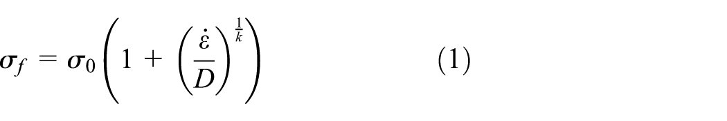
There are typically two popular formulae describing constitutive relations capable of incorporating the strain-rate implicitly. The first formula is the Cowper–Symonds power law proposed by Cowper and Symonds,
58
as described in equation (1). It must be noted that this equation is used to indirectly incorporate the strain rate rather than SRS. This power law was also used by many other investigations33,37,45,59–61 to incorporate the effect of strain rate in SP simulations. The two constants, D and k, have different values, respectively, corresponding to different materials, for example,
where
The second formula is the well-known Johnson–Cook function 63 described in equation (2). An investigation 64 shows that this equation is capable of predicting the stress–strain relationship well and is widely applied in SP for modelling the target material considering SRS. It is important to note that that these two formulae are used to represent strain-rate implicitly rather than evaluate SRS.

where
The above two equations support the observations that stresses decrease with a reduction in strain rates. Through both experiment and simulation, Klemenz et al. 48 presented that, lower strain rates corresponded to lower flow stresses under the same temperature conditions. It was also reported that the magnitude of maximum residual stress beneath the impact centre in the target material was smaller than that of maximum residual stress produced without consideration of SRS. 53 Hence, it can be seen that SRS is material-specific and has significant influence on target materials which are strain-rate sensitive.
Cyclic behaviour of the target material also has influential effects on the distribution of the induced residual stresses. 8 Both Sanjurjo et al. 8 and Klemenz et al. 41 found that exclusion of cyclic behaviour to a material model resulted in overestimation of residual stresses. In support of this, another investigation showed that the surface regions of the target material experienced arbitrary cyclic loadings and these loadings must not be neglected 53 since they could cause relaxation to the residual stresses induced by previous impacts.65,66 In multiple impact simulation, the target material encounters repeated impacts, hence cyclic loading occurs. 8 The mechanism to how cyclic behaviour affects the distribution of residual stresses is that the induced residual stresses can be relaxed by subsequent cyclic loadings that the target material undergoes during SP. Some research also showed congruent results. For example, experimental work by Gariepy et al. 42 showed differences in results with the consideration of cyclic behaviour and that without it. In addition, most materials ignoring cyclic behaviour possess elastoplastic hardening, as shown in Table 1, while those considering it display visco-plastic hardness behaviour.8,41,48,53,67
As aforementioned, the target material undergoes cyclic loading conditions 53 caused by multiple impacts in SP. 8 This cyclic loading may precipitate Bauschinger effects which redistributes the residual stresses if prior loading exists. 26 It was found that results ignoring Bauschinger effects lead to an overestimation of residual stress 22 and this could be validated by the differences between residual stresses produced by isotropic material models (not allowing for Bauschinger effects) and kinematic models (allowing for Bauschinger effects). 68 One possible explanation is that the Bauschinger effect has the potential to cause stress relaxation. 69 In order to investigate this effect, one interesting study conducted by Urriolagoitia-Sosa et al. 70 experimentally induced Bauschinger effects and proposed a strain-gauge-based method capable of measuring the resulting residual stresses. Sanjurjo et al. 8 drew a conclusion from the investigation by Bannantine 71 that Bauschinger effects should be taken into account if the kinematic hardening material model should be employed. Hence, it can be concluded that Bauschinger effect has significant influence on the residual stresses induced by SP and must be considered.
In order to investigate the influences of the above factors, Klemenz et al. 53 compared the residual stresses obtained from their numerical models (one isotropic hardening and one combined isotropic and kinematic hardening) to physical experiments. The comparison showed that the results from the combined isotropic–kinematic material model were in good agreement with the experimental results. The relevant material model was later introduced in the investigation conducted by Klemenz et al. 48 in an expanded way. As the above discussion in this section shows, the residual stresses would be overestimated when only considering SRS; however, they would be underestimated when only considering the cyclic loading effects and Bauschinger effects. 8 In general, the target materials in SP are strain-rate sensitive in most cases and undergo cyclic loadings. Therefore, it is appropriate to employ an elastic–viscous–plastic combined hardening material model when taking all these factors into account. 48
Thermal effects
Although SP is a cold work process, it still produces heat during impacts between the shots and the target material. 72 Harada and Mori 73 showed that the temperature alterations could affect the profile of residual stresses. Furthermore, the temperature increase could amount to 63°C when the cast steel shots reached the velocity of 50 m/s with a shot diameter of 2 mm under a so-called ‘adiabatic’ assumption. This observation was reported by Kirk 74 who conducted a series of tests with different air pressures ranging from 2 to 8 bar with three different flow rates of 20 flow (0.49 kg/min), 40 flow (0.88 kg/min) and 80 flow (1.58 kg/min) in the same investigation, as shown in Figure 5. Rouquette et al. 75 found that surface residual stress could have a maximum of 150 MPa discrepancy between models with and without consideration of thermal effects, while thermal properties just affected the magnitude of residual stress but not the distribution trend along the depth at impact centre of the target material. Apart from finding discrepancies of maximum 319 MPa of surface residual stresses, Hu et al. 76 further found that there were differences (maximum 1.66 mm) for arc height of Almen strips between models with and without consideration of thermal effects.
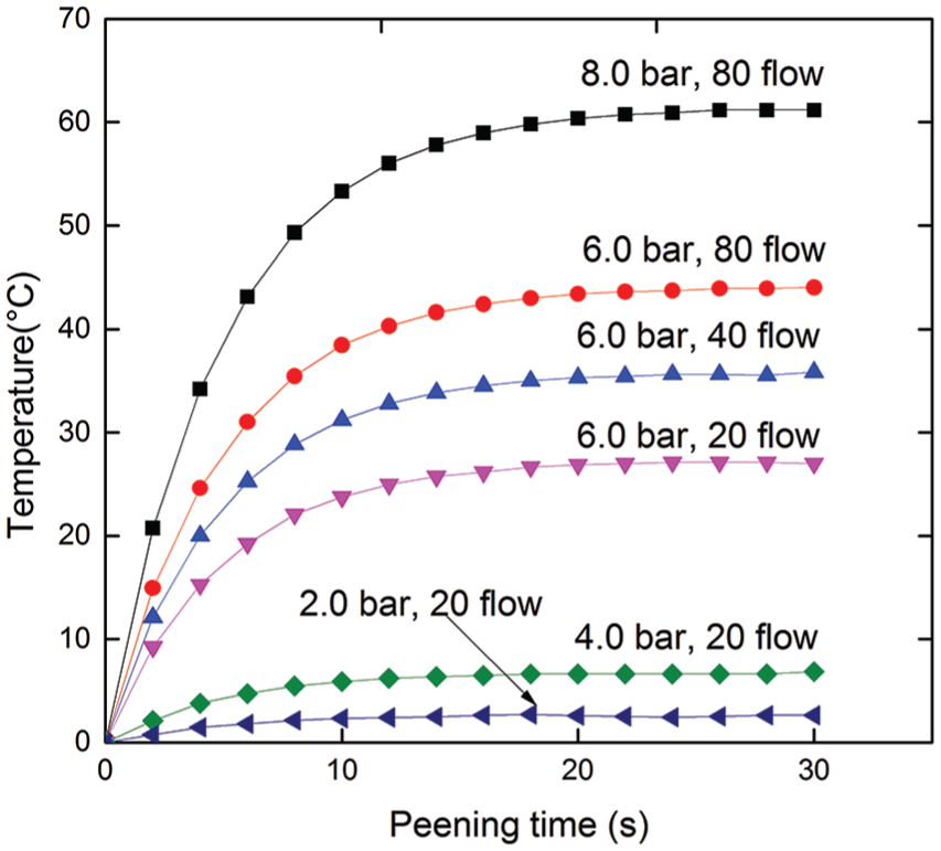
Heating curves for N strip during peening using S170 shot.
It can be seen that the residual stress decreases when considering thermal effects of the target material when employing either the Johnson–Cook model (see equation (2)) or the model proposed by Kocks et al.
77
During each impact, a fraction of the kinetic energy of shot is transformed into heat energy which causes surface temperature rises.
74
This increase would definitely lead to a decrease in the corresponding flow stress
Contrary to these researchers73,75,76 who concluded that thermal effects should be considered, many others insisted on not considering thermal effects. Kirk 74 reported that the increase in temperature was only a few degrees; and again ElTobgy et al. 38 concluded that the temperature rise was small in their model and that the corresponding thermal effects were not necessary by a comparison between results obtained from a model with and without consideration of thermal effects. Some other researchers such as Bagherifard et al. 55 and Gangaraj et al. 78 just neglected thermal effects in their investigations while they still obtained simulation results consistent with those from experiments. These contrary observations might arise based on the different parameters applied in the models. However, as discussed above, the temperature rise is affected by shot velocity, shot diameter, exposure time and so on. 74 Thus, whether to consider thermal effects in a model depends on whether the applied parameters are severe enough to cause thermal relaxation.
Friction
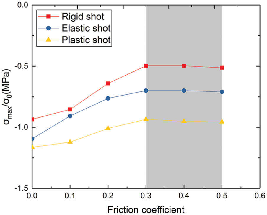
Many investigations have been carried out using Coulomb’s friction models and modified versions of them without any consistent conclusions on the influence of friction on the induced residual stresses being reached. Some researchers argued that friction had significant influence on the induced residual stresses,21,24,34,41,42,48,62,79,80 therefore most investigations took friction into account through application of friction models among which Coulomb’s friction model was widely applied.25,44,47,55,78 In these studies, some researcher hypothesised that there would be a threshold above which friction coefficient had no effects on residual stresses while under, it had significant effects. Taking the investigation by Kim et al. 33 as an example, effects of friction on residual stresses on the surface and beneath were observed and a threshold was assumed, as shown in Figure 6. The maximum residual stresses with respect to different shots, that is, rigid shot, plastic shot and elastic shot, increase with the increase in friction coefficient from 0 to 0.3, while no further changes occur when the friction coefficient ranges from 0.3 to 0.5, as shown by the shaded area in Figure 6.
Variation of friction (μ) affecting stress profile for α = 45°.
Regarding the threshold, different values were reported: 0.2 by both Han et al. 81 and Shivpuri et al. 35 in a case of 75°C impact; 0.1 by ElTobgy et al. 38 and Shivpuri et al. 35 in a case of perpendicular impact; and 0.25 by Meguid et al. 32 in a case of perpendicular impact. In another investigation, Ahmadi et al. 80 investigated the inhomogeneity of friction to plastic strain and reported that there was no threshold of friction to plastic strain while an optimum value was obtained at μ = 0.5. Below or above this optimum value, the change in friction coefficient could change the uniformity of distribution of plastic strain, while at this value, the plastic strain distributed most uniformly. Based on the threshold assumption, Shivpuri et al. 35 claimed that friction could not affect SP products since real friction coefficients were all higher than 0.1, which could be the threshold value according to their observation.
Some other investigators modified Coulomb’s friction model with the argument that Coulomb’s friction might be inappropriate to simulate the friction between the shot and the corresponding target surface. They consequently established their own customised friction model. Han et al. 81 and Meguid et al. 32 initially doubted the suitability of Coulomb’s friction and subsequently proposed a modification to it which was done by Han et al. 81 by taking relative movement in the contact area prior to slip into consideration. This kind of slip was also considered by Sherafatnia et al. 82 when evaluating the effects of friction on residual stresses; and moreover, the mechanism of sliding was described in detail in this investigation. It was found that the effect of friction was dominant on the distribution of residual stresses in surface layers, and that the surface residual stresses decreased, while the maximum residual stresses increased partially as the coefficient of Coulomb’s friction increased. A further systematic study is still missing on the modelling of friction and its effects on SP products.
Shot shape and material
It was reported that shot shape had effects on SP products,27,83 although many investigations on SP simulation did not consider shot shape as an influential parameter and hence used spherical shots.26,49,78 However, an early investigation was conducted by Meguid et al. 84 who used steel ellipsoids with different aspect ratios as shots. Their work revealed that the compressed layer of material thickened as the aspect ratio of shot increased. Consistent results were observed yielding that the smaller the aspect ratio, the smaller the maximum surface residual stresses and smaller the surface roughness. 85 Consequently, the theory of elastic solid contacts proposed by Hertz 86 (see equation (3)) was used by Fathallah et al. 87 for determining the average contact pressure. This investigation related coefficient of restitution to shot shape and also deduced that the plastic deformation caused by cut-wire shots was not as large as that caused by spherical shots

where P is the contact pressure;
Shots were also modelled with different material assumptions, that is, rigid,29,41,44,49 elastic55,78 and plastic25,79 in different investigations. The topic attracted great attention from researchers who investigated the influence of shot material on the induced residual stresses and plastic strains where it was found that there was a threshold of hardness ratio of shot material to target material 88 as confirmed by ElTobgy et al. 38 The threshold ratio was 2 and when the ratio was less than this value, significant influence of shot hardness on SP products was reported while when it was greater than it no obvious influence was observed. Furthermore, many studies reported congruent results with this finding: rigid shots led to overestimation of residual stresses32–34,38 as seen in Figure 6, where the stresses range from small to large when the shot material changes from plastic, to elastic to rigid. Another factor called a restitution coefficient was proposed and validated experimentally by Fathallah et al. 87 who comprehensively considered the influence of both shot hardness and shot shape. However, in industrial applications, shot materials usually had high hardness values compared to the corresponding target material 69 and large plastic deformation of shots were not acceptable. 32 Hence, the shots were usually modelled as rigid spheres.44,89,90
Coverage and intensity
Although coverage is one of the important parameters characterising reproducibility (including quality and effectiveness) of a SP79,91–93 process and must be controlled, 94 there were discrepancies in coverage definition used by different researchers and hence, the arrangements of shot impact (or impact order) varied.
Some early investigations simply counted the number of impacts on the target surface so as to study the development of residual stresses, while coverage determination in such models was not applicable and consequently ignored.52,95,96 It was observed in both simulation and experimental studies that subsequent impacts in the vicinity of the first impact area had influences on the surface residual stresses and the distribution of stresses beneath the surface. Hence, coverage was defined as a percentage of the peened surface (areas in plastic dents
16
) in relation to the whole target surface according to SAE J2277:2003,
97
as shown in Figure 7(a). Further investigations consistent with this coverage definition were carried out with distribution of impacts in various sequences on the target surface, as shown in Figure 7(b)–(d), so as to ideally determine the coverage and also avoid unnecessary computation cost.
34
It was found that both surface and maximum stresses increased as the centre distance of adjacent impact dents decreased. In contrast, other studies showed that impact sequence did not change the stress distribution but only the surface stress. These results are consistent with conclusions drawn by Baragetti.
98
In addition, Jianming et al.
99
found that the increase in coverage mainly improved the uniformity of residual stress field in the compressed area. Interestingly, Zhan et al.
100
validated this conclusion experimentally. In terms of angle of impact, Miao et al.
27
studied the effect of impact angle on coverage, showing that a smaller angle resulted in larger coverage than peening the component at angle

Coverage definition and the typical three arrangements of impacts: (a) definition of coverage which is the ratio of shading area to the rectangular area; and impact sequence in the order (b) 1-2-3-4, (c) 1-3-2-4 and (d) 1-2-4-3.
However, the above investigations neglected the flow behaviour of shots and randomness of impacts as in a real SP process, since these distributions of impacts are inherently exclusive with flow behaviour and randomness. Fortunately, the aforementioned FEM-DEMs have a promising potential to simulate these two characteristics of SP as they are more similar to industrial SP, its coverage is more related with time and is used together with intensity in the monitoring and control of SP.3,93,101 Hence, in our viewpoint, the definition of coverage from SAE J2277:2003 97 applied in a FEM-DEM model could better predict the outputs of SP numerically.
Besides coverage, intensity is extremely important to the reproducibility of SP93,94 and to explain real SP phenomena, 79 especially for controlled SP.3,44 The method to measure intensity was innovatively introduced by Almen et al. 102 and the measured intensity is called Almen intensity. It was found that a higher intensity could be produced by either larger shot diameter or enhanced shot velocity; consequently, an increase in intensity resulted in an increase in the magnitude of depth of the maximum residual stresses. 91 Moreover, surface roughness could also increase with increasing Almen intensity. 103
For the determination of saturation point of intensity, Karuppanan et al. 104 developed an algorithm by the means of a full regression analysis and fitted the experimental data by application of equation (4) which was also derived through data fitting by Miao et al., 44 Jebahi et al. 21 and so on
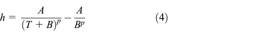
where A, B and
For numerically evaluating Almen intensity, Almen arc height h was related to residual stress profile through equation (5) by Guagliano 39 and related to impact number N by Miao et al. 44 using equation (6). These two equations were derived through fitting simulation results derived by other researchers such as Miao 89 and Tu et al. 106 Other equations to predict arc height of intensity through either coverage or number were derived by Kim et al. 79 based on an area-averaged solution. Encouragingly, results predicted by the two equations corresponded well with the experimental results obtained from Kim et al.24,34 The latest progress in this aspect is the prediction function for Almen height which was derived through the regression method. 107 This function revealed that peening time, shot diameter, air pressure and their combinations had significant effects on Almen intensity


where E is Young’s modulus of strip; l, b and t are, respectively, its length, width and thickness; M is the moment induced by residual stress; and
Numerical evaluation of residual stress and strain hardening
In terms of evaluation of residual stresses, the review found that the single-node average method was used widely by researchers such as Schiffner and Droste gen. Helling, 4 Han et al. 81 and Boyce et al. 59 at the early stage of finite element analyses. Then, node-average method was applied as attempts to obtain more accurate residual stresses. This method evaluates the residual stresses of the impact centre by averaging the stresses at the surrounding nodes. Four nodes involved in the averaging is called four-node-averaged method and nine nodes involved is called nine-node-averaged method. 34 Subsequently, this method was modified by expanding from averaging a portion of nodes to averaging all the surrounding nodes. This expanded method is called area-averaged method. 79 Finite element results obtained through the area-averaged method were reported to have better correlation with experimental data obtained through the X-ray diffraction method 34 since the X-ray diffraction method is also an ‘area-averaged79,108 method.
Notably, material hardening is a favourable product of SP which directly enhances the hardness of the target material4,72,109 by increasing the yield stress of the material.5,110 Material hardening occurs due to the dislocations within the crystals of the material.5,111 The comprehensive process of the formation of these dislocations is nicely detailed by Kirk 111 where it was reported that material hardening was affected by several parameters of SP, such as intensity 5 and peening time. 112 However, it is easily mistaken that increasing these parameters would strengthen the effect of strain hardening, which is not true as the hardening is annihilated when the plastic strain reaches a certain value and a larger strain will just induce material softening. 72 For this reason, it is important to assess the contribution of strain hardening induced in the target material or evaluate the beneficial effects of strain hardening. The direct approach to evaluating strain hardening is to evaluate the hardness of the peened and unpeened materials, respectively. The method for evaluating Brinell’s hardness recommended by Kirk 113 is expressed in equation (7)

where
However, assessment of the effects of strain hardening is complex. Since strain hardening improves the fatigue life of the material, one method could be identifying the difference between the S-N curves of peened and unpeened materials. 111 The disadvantage of this method is that it cannot differentiate the effect of strain hardening from the improved fatigue life of the peened material which is the complimentary effect of strain hardening and CRSs. The other method proposed by Kirk 111 is used to separate the effects of the two contributors, namely, strain hardening and CRS. This method realises the assessment of the respective contributions of strain hardening and CRS pictorially through comparisons between the two Goodman lines of the unpeened material without alternating stresses and peened material with alternating stresses. The corresponding cross-hatched area of the two Goodman lines represents the contribution of strain hardening.
It can be said that the above methods do successfully characterise the effects of strain hardening on a material, depending from which perspective it is analysed. Furthermore, the evaluation of hardness is a direct and quantitative way to depict the effect of strain hardening on a material, and the other two methods reflect the effect of both through the improved fatigue life of the material with the differences being that one is done via S-N curves, while the other is assessed through Goodman lines.
Numerical optimisation
Objective functions
As shown in Figure 2, SP is affected by many factors and mainly has three products, namely, residual stresses, surface roughness and cold work. In optimisation studies, different investigations considered different factors and responses due to limited physical conditions or specific purposes. Some responses were simplified by emphasis on some aspects of their corresponding responses. For example, residual stresses refer to many aspects, namely, surface residual stress, maximum residual stress and distribution of residual stresses, but the objective might be just set as some of these aspects rather than all of them. In order to illustrate these variables, a Cartesian coordinate system is defined with residual stress as its abscissa (labelled
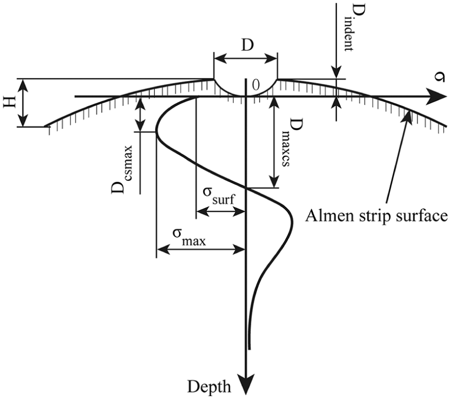
Schematic diagram of responses relevant to optimisation objective.
The variables (products of SP) in Figure 8 can be divided into three kinds, namely, residual stress, cold work and surface roughness. Residual stresses on the top layer are beneficial to enhance the fatigue resistance of the target material, hence it should be maximised. Nevertheless, the cold work may lead to stress relaxation of CRS on one hand, 11 and on the other hand, surface roughness in terms of the height of the cavities caused by impacts which have the potential to weaken the benefits of CRSs by causing corrosive cracks 83 and stress concentrations. 11 Thus, these two products are unfavourable in industrial applications and thus should be controlled to acceptable levels. Furthermore, these SP products are measurable: the residual stresses could be evaluated by several methods, such as the area-averaged method as aforementioned; the cold work can be calculated by measuring the material plastic strain at the yield point of the target material; and the surface roughness can be calculated by measuring the plastic strain of the peened surface. 45 Therefore, with the consideration of both SP effects on target material and measurability (quantification) of these effects, applicable objectives of the SP optimisation should be as follows: (1) maximisation of the CRSs, (2) minimisation of cold work and (3) minimisation of surface roughness.
Maximisation of residual stress
Induction of compressed residual stresses to enhance fatigue life of components is the initial purpose of utilisation of SP surface treatment; hence, maximisation of residual stresses (such as
Minimisation of surface roughness
The surface roughness relevant responses, namely,

Minimisation of cold work
Cold work is another response to be minimised which was set as a minimisation sub-objective function of optimisation in the investigations conducted by Levers et al., 114 Romero et al. 109 and Baskaran et al., 11 where it was defined as the amount of true plastic strain producing the observed diffraction peak broadening 116 and was expressed as a function of material strain parameters, 45 as described in equation (9)

where
Other objectives
Besides the above three frequently used objectives, some other responses were also used as optimisation objectives, such as fatigue life, 109 coverage, 117 Almen height (H)/intensity of target component6,107,117 and difference between the desired deformation and the real deformation. 118 Coverage and intensity are basically two control parameters and are recommended by the authors of this work to be constraints rather than objectives. It should be noted that material hardening unfortunately has not been specified as an objective function although it actually has a very significant effect induced by SP. 72
Tackling method with multiple objectives
It can be seen that the optimisation is a multi-objective problem and the sub-objectives may conflict with each other so that they cannot be optimised simultaneously. Furthermore, most multi-objective problems just have several feasible solutions rather than only one optimum solution. A popular method called the weighted-sum
119
may produce different optimum solutions led by the alternative weights. Another popular method is
Design constraints
For optimisation purposes, only influential and also controllable parameters were taken into account in the reviewed literature and are summarised in this work. These parameters include the initial velocity, diameter of the shot, incidence angle, exposure time, material of shot and target, and coverage. Each parameter here has its own range which is discussed as follows.
First, the initial velocity could be specified from 20 to 100 m/s according to Frija et al., 15 while Marsh 121 set it as 40 to 120 m/s. Although Soady 3 contended that it ranged from 40 to 70 m/s, the range from 20 to 120 m/s could safely cover the whole range from an industrial perspective. Second, the size/diameter of shots should be discrete values between 0.0450 and 4.75 mm 122 and the values are specified in SAE. 122 Note that most researchers 123 specified the values according to this range, while 38 mm was used in a 3D model by Klemenz et al. 48 for the purpose of easy validation with a physical experiment. However, it should be noted that such a large shot was developed specifically for the purpose of easy validation with physical experiments but should not be advocated. Third, values of the incidence angle could be specified at a range of 45°–90° with respect to the target surface 33 since this range has no controversy and is economical in terms of the utilisation of the shots’ kinetic energy. However, values ranging from 0° to 45° was also used by Shivpuri et al. 35 where it was demonstrated that incidence angle at this range has a feeble effect on SP results. 33 Fourth, pre-stressing conditions for SP could be set as pre-stressed or not, since pre-stressing techniques could increase the maximum CRS. 124 Fifth, the exposure time could be simplified as the peening time on the surface since the longer the exposure time, the larger is the probabilistic peening time of the surface. Sixth, the material of shots could be specified as the commonly used materials, namely, ceramic, steel and glass, according to Champaigne 125 and Frija et al. 15 Finally, the target material should be specified according to what kind of component a researcher is studying since different components have different material compositions.
Interestingly, in some investigations, intensity and coverage were also set as constraints. Coverage was taken as a constraint with two levels (one impact or two at the impingement centre) by Baragetti 1 who concluded that percentage of coverage could be one of the most important factors affecting residual stress field. Subsequently, both coverage and intensity were constrained by Romero et al. 109 and Vielma et al., 103 who derived the same conclusion that coverage could be one of the most influential factors affecting the profile of residual stresses. Some other variables were also set as constraints, such as peening duration (exposure time),12,107,115,117 mass flow rate, 115 nozzle distance,12,117 air pressure,12,103,107,115,117,126 friction 11 and interaction effects,107,115 among these variables. Note that some of these factors have relationships more or less to factors mentioned above. For example, air pressure is highly related to shot velocity yet they emanate from different models, that is, shot velocity from 3D finite element models while air pressure from particle models.
Tools and models for SP
There are mainly two kinds of models used in SP optimisation, namely, finite element models and approximation models. The latter models work as approximations/surrogates of the input/output function. They are formulated based on the fundamental input/output data produced by numerical simulation or physical experimentation through some specific methods, 127 such as response surface method and polynomial fitting methods.
Early investigations conducted developed finite element models directly for the optimisation of SP. An interesting 3D finite element model for optimisation was created by Baragetti 1 with 100% coverage (single-shot impact) and 200% coverage (two-shot impact at the same location) in Abaqus explicit code. Four inputs, including shot diameter, shot velocity, plate material and coverage, were set for this model and only two levels for each input. Another important model combining finite elements with discrete elements was created by Miao et al. 27 in Abaqus code synthesising with an EDEM code. The model considered flow rate and coefficient of restitution first in optimisation model and also took interactions between shots into account. Although the model focused on optimisation of CRSs, it did not consider surface roughness which is detrimental to material fatigue life.
However, approximation models are usually established on the basis of simple finite element analyses or physical experimental results through different methods such as radial basis function (RBF), response surface methodology and polynomial function. By the utilisation of RBF, Baskaran et al.
11
created an approximation model in PEZ software with shot radius, incidence angle and shot velocity as inputs and CRS, cold work and surface roughness as outputs, respectively. They compared the prediction precisions among the polynomial model, RBF model and the finite element model and concluded that the RBFs had the highest prediction precision covering all sampling points, which is favourable for optimisation. The response surface method was applied through a polynomial function (equation (10)) in Minitab code107,115 and Design-Expert code
117
for establishing surface responses, respectively, for outputs in relation to inputs. The outputs include residual stresses, surface roughness, arc height, surface hardness, coverage and intensity, and the inputs include nozzle size, nozzle distance, pressure, flow rate, angle and exposure time. The models established through this equation were capable of studying interactions between design variables through the crossing item,

where Y is the surface response;
Other models were also used in SP optimisation studies such as an analytical model which was created by Hu et al. 118 based on an assumed relationship between arc height and exposure time in MATLAB code. It used a notional temperature gradient to approximate macroscopic deformation and only took plastic deformation into account. However, this model over-simplified the SP process drastically that it could not even evaluate CRSs.
Optimisation algorithms
Design of experiments methods
Many studies on SP optimisation have been done using different optimisation methods so far among which the most commonly used method is the design of experiments (DOE). An early important investigation done by Baragetti 1 using Taguchi’s method to analyse the numerical simulation results of SP resulted in the optimisation of seven parameters. Later, Evans 110 derived mathematical expressions for the indentation of surfaces and proposed a plausible procedure for the optimisation of SP. Rodopoulos et al. 17 used the effects neutralisation model, apart from the DOE, to optimise the parameters of SP and efforts were made to define the optimum levels and tolerances. One of their important initiatives was the stress relaxation that was employed to examine the stability of CRSs. Nevertheless, there were only two levels setting to each parameter specified. George et al. 6 used Taguchi’s method to optimise process parameters of SP with two levels of each design variable from the selected four parameters and analysed interactions between the parameters. However, the shortfall of these investigations comprises the following: (a) symmetric BCs were used which lead to imbalance of in-depth residual stress profile according to Klemenz et al.41,53; (b) the rigid shot assumption may increase the amplitude of CRSs; (c) the optimisation objective is only the CRSs; and (d) most importantly, the setting of only two levels for each parameter affects reliability of the results. 1 Unfortunately, all these investigations using the DOE method limited their design variables to two levels, which led to loss of fidelity of the results to some extent. The reason may be that an increase in level number would increase the number of iterations required for a solution and thereby increase computational cost.
Other algorithms
Besides the DOE, other methods were also used for optimisation of SP. Baragetti et al. 128 proposed a numerical procedure which could predict SP effects through a non-dimensional function. With this numerical procedure, it is possible to choose SP parameters for a particular application. Petit-Renaud et al. 115 established an empirical relationship between input variables, such as exposure time and nozzle size, and response variables (residual stresses and their corresponding distance to the target surface); and based on this relationship, they optimised the process parameters. Miao et al. 5 independently considered the surface integrity as the optimisation objective to optimise a SP process. Later, using genetic algorithm, Baskaran et al. 11 set the increase in residual compressive stress, reduction in surface roughness and cold work as objectives of an optimisation function and achieved an optimised set of parameters. This was a multi-objective optimisation which first considered friction between the shot and its corresponding surface. This investigation resulted in the determination of the optimum area under the CRS curve while keeping the cold work and surface roughness under the specification limits. Recently, the Box–Behnken design (BBD) method was used by Nam et al. 117 who set the Almen height as the objective of a desirability function and claimed that BBD provided high-quality predictions in investigations on linear, quadratic and interaction effects of parameters.
Critical analysis of the optimisation algorithms
Among these investigations, Baragetti et al. 128 developed a software package for the prediction of compressive residual, and Petit-Renaud et al. 115 used a non-orthogonal experimental design and fitted multiple regressions to the results. The disadvantage of these investigations is that these researchers just regarded the SP as a single objective problem which does not correspond to a real SP process. Miao et al. 5 did not optimise the SP process while their investigation on the relationship between parameters and the responses, namely, residual stresses and surface roughness, is very important for further optimisation work. The wide application of the DOE algorithm could perhaps be due to it not requiring highly skilled staff and is cost-saving, efficient and capable of taking interactions between variables into consideration. However, it is not applicable when the range of variables is wide and the variables are continuous. Nearly all the investigations with DOE aforementioned did not consider more than three levels of each variable. BBD and other similar algorithms have similar disadvantages to DOE. Contrarily, some recently developed modern algorithms, such as the genetic algorithm, displayed promising results for searching optimal combinations of parameters. In this regard, Baskaran et al. 11 conducted a very comprehensive investigation on the optimisation of SP, However, its drawback was that the study did not consider the independence test of those influential parameters before optimisation and material hardening was also not considered.
Summary and discussions
This article comprehensively reviewed the definition, influential parameters, responses and different aspects of numerical simulation and optimisation of SP found in the existing literature in recent years. The work reviewed is summarised and concluded as follows.
Regarding the simulation of SP, 3D models are currently the mainstream since they are capable of considering coverage and predicting the distribution of residual stresses more precisely. The FEM-DEMs, however, are becoming increasingly mature and show their advantages in incorporating flow behaviour and randomness of shots. More attention is expected to be paid to this type of models in future. The SP process can be simulated through two analysis steps, that is, combining a dynamic step with a sequential static step. High emphasis was paid on the material modelling of target material since it is the key factor influencing the responses of simulation models of SP. SRS, cyclic behaviour and Bauschinger effects are recommended to be taken into account simultaneously since considering only one of them may lead to unreliable residual stress distributions. In general, the target materials in SP are strain-rate sensitive in most cases and always undergo cyclic loadings. Therefore, it is appropriate to apply an elastic–viscous–plastic combined hardening material model when taking all these factors into account. Thermal effects are expected to be incorporated when thermal loadings are capable of causing stress relaxation though it does not reach such severity in most cases. Friction between shots and a target material is expected to be systematically studied in future works. The most prevailing shot shape is a spherical solid and the material is usually set as rigid although the shape and material are reported to having influences on the distribution of residual stresses. There are discrepancies in the definition of coverage and intensity though they are two critical controllable factors characterising the reproducibility of a SP process and the standard definitions from SAE are highly recommended for them. The area-averaged method for numerically evaluating residual stresses is currently reported to produce the most accurate results. Different methods are available for the characterisation of strain hardening though their reliability needs to be assessed in context accordingly. The review also showed that material hardening is one of the important benefits of a SP process although it has not received its deserved attention.
In terms of numerical optimisation, the prevailing objective function is the distribution of residual stresses though cold work and surface roughness also received a certain extent of concern. In essence, cold work is highly related to surface roughness which can be readily seen from their definitions. Material hardening, more specifically the hardness enhancement, has not been set as an objective function so far although it is as beneficial as residual stresses. The coverage and intensity of SP are commonly excluded in most optimisation research though they are critical control parameters. The influential parameters recommended as design constraints are initial velocity, diameter of the shot, incidence angle, exposure time, material of shot and target, coverage and intensity. SAE has some standards specifying the ranges of these parameters. The main models applied in optimisation are the finite element and approximation models. DOE is the most widely applied algorithm because of its advantages. However, it is not applicable when the range of variables is wide and the variables are continuous. Nearly all investigations with DOE aforementioned did not consider more than three levels of each variable. On the contrary, some recently developed heuristic algorithms, such as the genetic algorithm, showed promise in searching for optimal combinations of parameters. It can be easily seen that approximation models based on finite element simulation models have obvious advantages in terms of computational costs. The models used in simulation are generally different from those in optimisation. The reason might be that SP models for optimisation are required to be as simple as possible in order to avoid high computational times arising from numerous iterations. However, it can be expected that these algorithms, blending with approximation models, are to attract more attention of future researchers.
Footnotes
Acknowledgements
The authors of this work would like to acknowledge the financial support provided by Eskom Power Plant Institute (EPPI), the University of Pretoria, and the technical support received from Dr G Mitchell of FEAS (Pty) Ltd.
Handling Editor: Daxu Zhang
Declaration of conflicting interests
The author(s) declared no potential conflicts of interest with respect to the research, authorship and/or publication of this article.
Funding
The author(s) disclosed receipt of the following financial sup-port for the research, authorship, and/or publication of this article: The authors greatly appreciate the support of Eskom Power Plant Engineering Institute (Republic of South Africa), University of Pretoria and Tshwane University of Technology for funding this research.