
Abstract
Purpose of this study is to develop a solenoid actuator that can be used for natural gas injector. Operation of the solenoid injector is described by two mathematical models including an electrical model and a mechanical model. The solenoid injector is also modeled and simulated in Maxwell and Simplorer based on the specifications of a real solenoid injector. The operating characteristics of the solenoid injector, including the current, electromagnetic force, and displacement of the plunger, are investigated under the effects of input parameters. In addition, experimental systems are established to examine the electromagnetic force and the plunger displacement in the solenoid injector under the effects of air gap and input voltage, respectively. The simulation results show that the electromagnetic force and displacement of the plunger can be easily increased by reducing the length and increasing the width of the cross-sectional shape of the coil. In addition, the increased length and diameter of plunger also contribute to improving the electromagnetic force. The increase in plunger mass results in fluctuating plunger displacement, which can affect the quality of injection. The simulation results are validated by experimental results on the effects of air gap and input voltage.
Introduction
A solenoid actuator is an electro-mechanical device that converts electrical energy into mechanical energy associated with linear motion. 1 Solenoid actuators are used in a wide range of industrial applications such as fuel injection systems, starting motors, industrial valves, and loudspeaker. 2 A fuel injector is a small electric solenoid that very precisely controls fuel flow. 3 In general, an electric solenoid can be used in three kinds of injectors, including gasoline, diesel, and gaseous fuel injectors.4–8 A solenoid for gaseous fuel injectors is being developed for natural gas and hydrogen fueled engines for its environmental benefits.8–12 Common gaseous fuel injectors can be classified into two types, gaseous fuel injections in the manifold and direct gaseous fuel injections in the cylinder. The gaseous fuel injectors installed in the manifold do not differ much from gasoline injectors in operating principle but their detailed structure, materials and injection pressure are significantly different when compared with the gasoline injectors. The gaseous fuel injectors installed in the manifold usually have injection pressure from 5 to 10 bar, 13 while the port gasoline injectors are usually operated at pressure in the range of 3–5 bar. 14 The gaseous fuel direct injectors require new technology to adapt to high-pressure gas injection and precision. Recently, there have been many investigations of solenoid-type gasoline and diesel injectors,15–26 but there are very few investigations of gaseous fuel injectors using electric solenoids. Therefore, gaseous fuel injectors using electric solenoid valves ought to be investigated further. Some previous studies related to solenoid gas injector could be found in Lee et al. 27 and Kekedjian and Krepec. 28 HR Lee et al. 27 presented an optimum design of a solenoid actuator to ensure reliable operation of the solenoid actuator when applied for hydrogen storage cylinder valves of a fuel cell vehicle. They conducted an electromagnetic field analysis using Maxwell V15 for ensuring reliable operation of the solenoid actuator, which was performed by magnetostatic technique based on the distance between magnetic poles. However, they did not analyze a transient mode for plunger motion which related to stability of the solenoid. H Kekedjian and T Krepec 28 developed solenoid gas injectors with fast opening and closing, in which the mathematical models including steady-state and transient solenoid model, electrical model, mechanical model, and fuel flow model were used to predict and optimize the operation of the solenoid gas injectors. In addition, in order to make the solenoid gas injectors with better effective and reliable operation, they conducted some modifications for the solenoid gas injectors; for example, solenoid body was attached to the upper cap, shorter solenoid was adapted, injector needle rod was made more elastic to reduce the needle bouncing, needle seat was made with a reversed differential angle. Besides the investigations mentioned above,27,28 there are some other studies related to solenoid gas injectors.29–31 The previous studies provided useful information for investigating and designing a high-performance solenoid gas injector. However, it is not enough to understand the operating characteristics of the solenoid under various conditions. Displacement of the plunger and electromagnetic force are important considerations when designing a solenoid injector because they relate to fuel injector performance. 32 Therefore, to develop a solenoid gas injector with a high operating performance, an investigation of the dynamic characteristics of the solenoid needs to be conducted based on effects of designed parameters. Unlike the previous studies,27–32 this study develops a solenoid for natural gas injector by investigating its dynamic characteristics based on the effects of many designed parameters. In addition, experimental systems are also established to examine the dynamic characteristics of the solenoid injector under the real condition.
In this article, the operating principle of the solenoid injector is described by electrical and mechanical models. The solenoid injector is also modeled and simulated based on simulation tools such as Maxwell and Simplorer. In order to model in Maxwell, the geometry of the solenoid injector is first built in the computer-aided design (CAD) drawing software based on the dimensions of a real solenoid injector. The expected results in Maxwell include flux density, magnetic field, and magnetic induction. The simulation results obtained in Maxwell are combined with the Simplorer software to simulate operating characteristics such as current, electromagnetic force, and displacement of the plunger. To predict and support for designing a high-performance solenoid injector, a parametric study is conducted with the effects of designed parameters such as cross-sectional shape of the coil, plunger length, plunger diameter, gas pressure, spring stiffness, mass of plunger, and number of coil turns. Besides the simulation study, experimental systems are established to examine the electromagnetic force and plunger displacement in the solenoid injector.
Simulation study
This study is conducted to simulate the operating characteristics of a solenoid used for a natural gas injector, which is based on the specifications of a real solenoid-type natural gas injector, as shown in Figure 1(a) and Table 1.
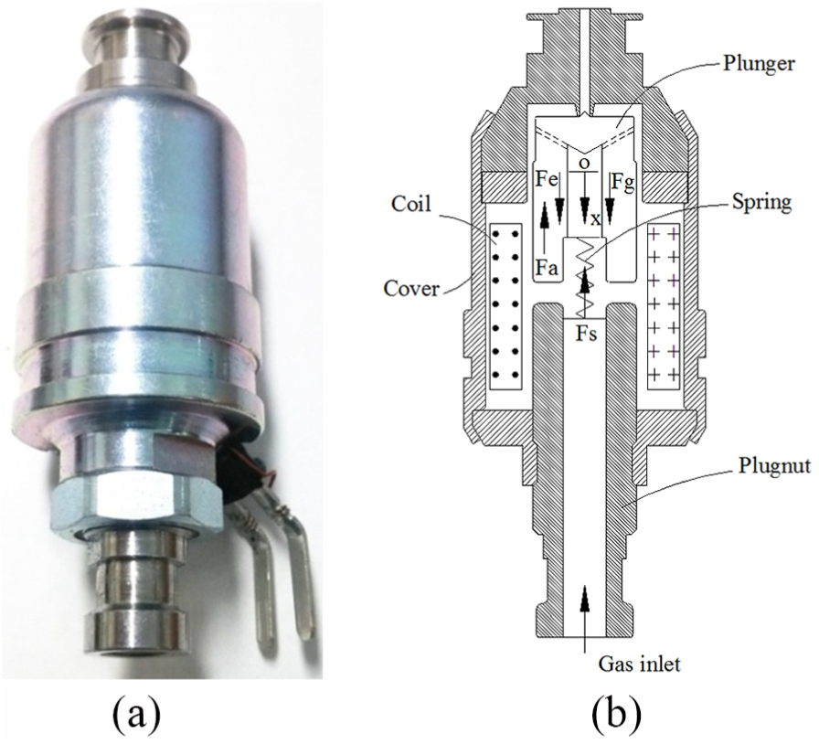
(a) Solenoid-type natural gas injector and (b) free body diagram of the solenoid injector.
Specifications of the solenoid injector.

Mathematical models
Electrical model
The relationship between voltage and current in the solenoid injector can be presented as 33

where vo is the input voltage, R is the resistance in the coil, i is the current, and λ is the total flux linkage of the winding.
The total flux linkage of the winding is proportional to the total magnetic flux ϕ, as shown by the following relationship

where N is the number of coil turns.
Therefore, equation (1) can be rewritten as follows

In addition, the total flux linkage of the winding is also presented as a function of the current

where L(x) is the inductance of the system.
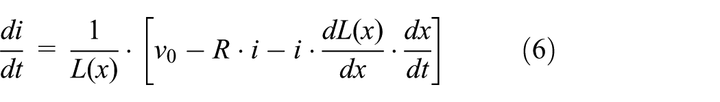
By combining equations (1) and (4), the relationship between voltage and current can be rewritten as follows

Mechanical model
Based on modeling of the solenoid injector described in Figure 1(b), a mathematical model for a mechanical subsystem is defined by Newton’s second law
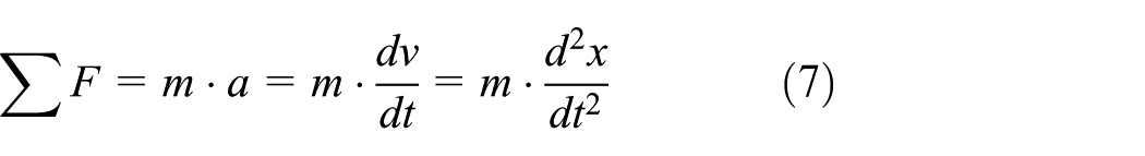


where m is the mass of the plunger, a is the acceleration of the plunger, v is the velocity of the plunger, Fe is the electromagnetic force, Fs is the spring force, Fd is the damping force, Fa is the gas force, Fg is the gravitational force, k is the spring stiffness, b is the damping coefficient, x is the position of plunger, x0 is the initial position of the plunger, and g is the acceleration due to gravity.
In the mechanical model, the electromagnetic force (Fe) generates when the solenoid injector is energized by an electric voltage. This force applies on the plunger and makes it move in the solenoid. 34 As can be seen in Figure 1(b), the plunger is moved down by the electromagnetic force. However, the resistance forces such as spring force, damping force, and gas force are also generated against the movement of the plunger. The electromagnetic force is considered as a connecting element between the mechanical and electrical models based on its relationship with the current as shown as follows 35

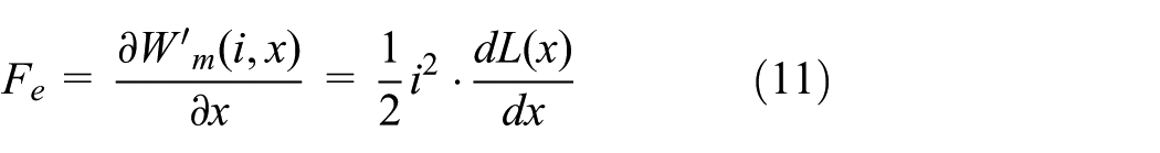
where
The inductance of the system (L(x)) is calculated by the following relationship 36
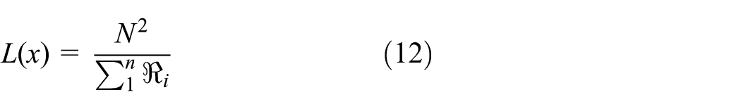
where N is the number of coil turns and
The number of coil turns relates to magnetic field intensity H, as shown by Ampere’s law36,37

where ℓ is the length of the closed magnetic path 37 and i is the current.
Modeling in Maxwell and Simplorer
Modeling in Maxwell
A two-dimensional (2D) drawing of the solenoid injector is created first in the CAD drawing software before importing it to Maxwell for simulating the flux, magnetic field, and induction. The next step is to make a 2D solenoid injector model in Maxwell based on the specifications of a real solenoid injector, as shown in Figure 2.

Model of the solenoid injector in Maxwell.
The components of the solenoid injector include a plugnut, a lower casing, an upper casing, a yoke, a coil, and a plunger. In the Maxwell model, each component of the solenoid injector is assigned a material, as shown in Table 2. Afterward, a boundary condition is applied for the plunger, viewing it as a moving object under the effect of an electromagnetic force. An excited element is applied for the coil by assigning it as an element excited by current to create the electromagnetic force applied to the plunger.
Materials of the solenoid injector.

Modeling in Simplorer
Operation of the solenoid injector is simulated based on the equivalent circuit, including electrical and mechanical aspects, as shown in Figure 3. The electrical circuit provides input voltage to the coil to control plunger movement through electromagnetic force. The mechanical circuit describes the forces that apply to the plunger during its movement, as shown in equation (6). In order to simulate the operation of the solenoid injector with the equivalent circuits mentioned above, the Simplorer software is used as a solver. At first, a 2D model of the solenoid injector is exported from Maxwell with defined materials, boundary conditions, coil resistance, and number of coil turns. Afterward, this 2D model is imported to Simplorer to simulate the operating characteristics such as current, electromagnetic force, and displacement of the plunger. In order to provide information for this study, a parametric study of the operating characteristics of the solenoid injector is conducted with the effects of input parameters, such as cross-sectional shape of the coil, plunger length, plunger diameter, gas pressure, spring stiffness, mass of the plunger, and number of coil turns.

Equivalent circuits of the solenoid injector in Simplorer.
Simulation results
Flux, magnetic field, and magnetic induction
Figures 4–6 show the results of flux, magnetic field, and magnetic induction on the effects of the gap between the plugnut and plunger. It can be seen that the highest flux density is concentrated in the inside edges of the plugnut, lower casing, and yoke, where the flux line is displayed in red. The maximum flux density is increased as the plunger moves toward the plugnut. This is shown by closer flux lines, while the length of the flux lines is abridged as the plunger moves toward the plugnut, as shown in Figure 4. Figure 5 shows that the magnetic field is concentrated in the gap between the plunger and the plugnut. The value of the magnetic field also increases by reducing the gap length, as shown in Figure 5. This can be explained by the increase in magnetic induction when decreasing the gap length, as shown in Figure 6.

Effects of the gap on the flux lines.

Effects of the gap on magnetic fields.
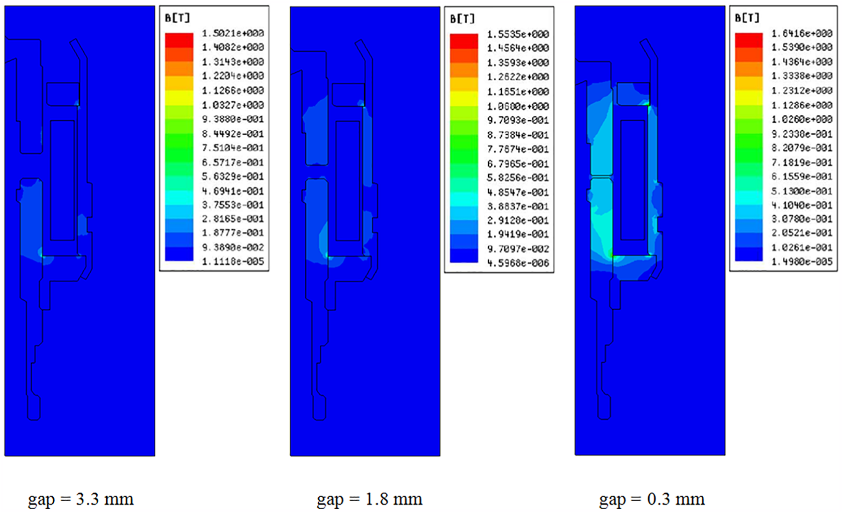
Effects of the gap on magnetic induction.
Effects of cross-sectional shape of the coil
Cross-sectional shape of the coil relates to the distribution of magnetic field around the plunger, which would also affect the electromagnetic force and plunger displacement. The types of the cross-sectional shapes of the coil are described in Figure 7. Therein, the cross-sectional area of the coil is maintained at a constant with a value of 48 mm2, while changing length and width dimensions.

Types of cross-sectional shape of the coil: (a) type I, (b) type II, and (c) type III.
Effects of the various cross-sectional shapes on the current, electromagnetic force, and plunger displacement are shown in Figure 8. It can be seen that the variation in the cross-sectional shape of the coil leads to a small change in the response time of the current. Namely, the current of type III increases faster than that of type I and type II, as shown in an enlarged picture of Figure 8(a). The variation in cross-sectional shape of the coil also significantly affects the electromagnetic force, as shown in Figure 8(b). The electromagnetic force is considerably increased by adjusting the cross-sectional shape of the coil from type I to type III. This can be explained by the number of turns around the plunger. When the cross-sectional shape of the coil is changed from type I to type III, the number of turns around the plunger increases while distance between the plunger and center of the coil reduces; thus, the magnetic field is stronger.38,39 As the result, the electromagnetic force increases when the cross-sectional shape of the coil is changed from type I to type III. The increased electromagnetic force results in increasing plunger displacement, as shown in Figure 8(c).

Effects of cross-sectional shape on (a) current, (b) electromagnetic force, and (c) plunger displacement.
Effects of plunger length
The length of plunger is denoted as L. It is one of important parameters and decides the amount of energy that plunger can be received. To show how plunger length affects the operating performance of the solenoid injector, a predicted study is necessary. In this study, the plunger length is varied at three various values including 13, 14, and 15 mm. The effects of plunger length on the electromagnetic force and plunger displacement are shown in Figure 9.

Effects of plunger length on (a) electromagnetic force and (b) plunger displacement.
As can be seen in Figure 9(a), when the plunger length is varied from 13 to 15 mm, the electromagnetic force is increased from 1.84 to 2.11 N (12.49%). In other words, the longer plunger receives more energy than a short one, which implies that it also transfers more energy because of the conservation of energy. This is explained that the increased length of plunger results in a greater appearance in the magnetic field. As the result, the longer plunger receives more energy and makes a greater electromagnetic force when compared with a short one. The increase of electromagnetic force leads to increasing the displacement of plunger, as shown in Figure 9(b).
Effects of plunger diameter
The variation of plunger diameter directly affects the electromagnetic force due to varied magnetic flux density between plunger and coil. In other words, each value of plunger diameter will decide a respective value of the electromagnetic force. In this study, plunger diameter is denoted as d. To provide information for this study, the diameter of plunger is varied at 10, 9.4, and 8.8 mm. The effects of plunger diameter on the electromagnetic force and plunger displacement are illustrated in Figure 10.
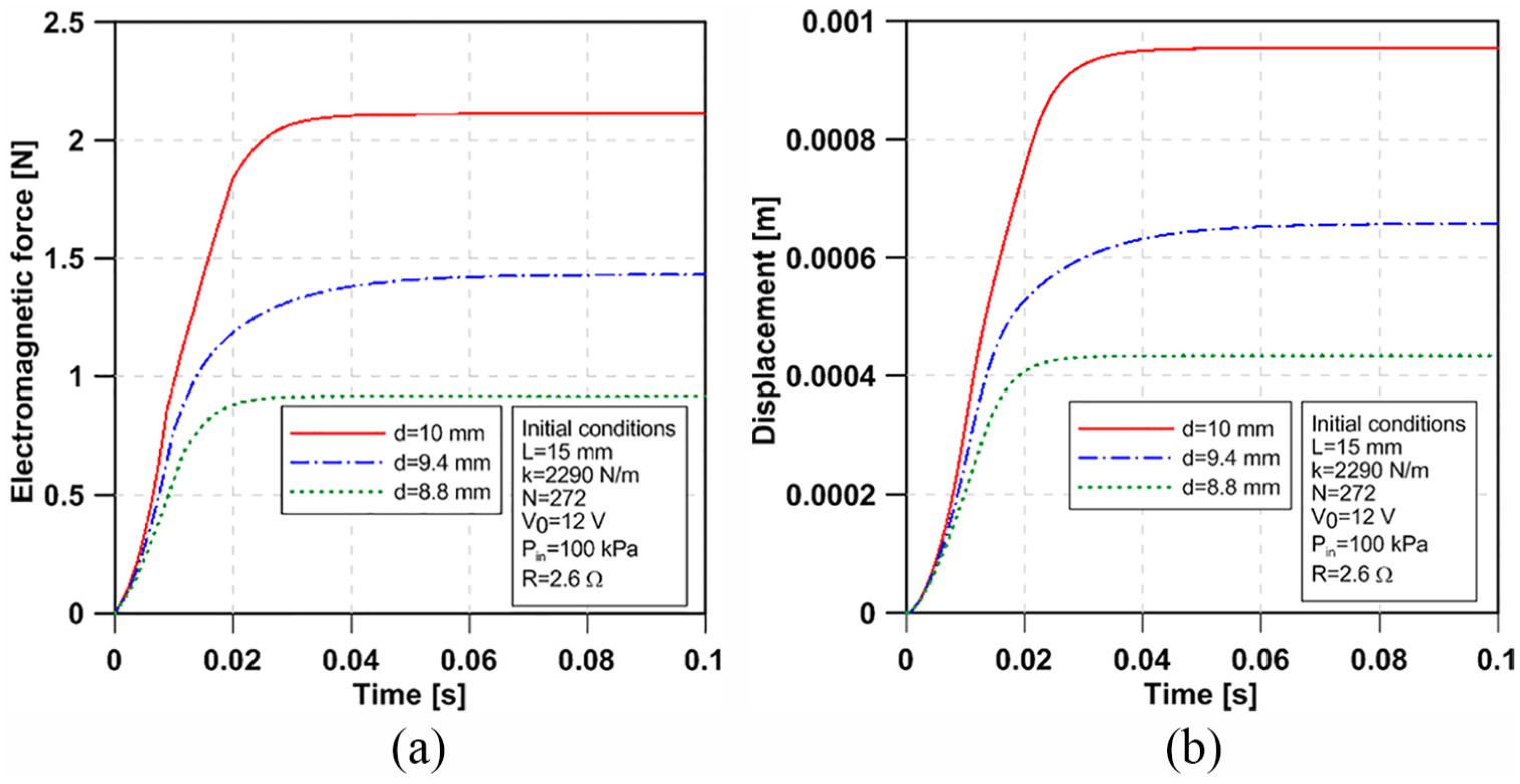
Effects of plunger diameter on (a) electromagnetic force and (b) plunger displacement.
The simulation results show that the decrease of plunger diameter makes decreasing the electromagnetic force, as shown in Figure 10(a). Namely, when the plunger diameter is adjusted from d = 10 mm to d = 8.8 mm, the electromagnetic force is decreased from 2.11 to 0.92 N (56.39 %). This is because the decreased plunger diameter results in decreasing the magnetic flux density in the plunger and region of the gap; thus, the electromagnetic force is reduced when the plunger diameter is decreased, as shown in Figure 10(a). The decreased electromagnetic force caused by the decreased plunger diameter results in decreasing the plunger displacement, as shown in Figure 10(b).
Effects of gas pressure
In the operation of the solenoid gas injector, the motion of plunger is not only effected by resistance force of the spring, but also effected by resistance force of the gas (Fa), which is generated by gas pressure in the solenoid injector (Pin). To provide information for this study, the effects of gas pressure on the operating characteristics of the solenoid injector are investigated, in which, the gas pressure is varied at 100, 400, 600, and 800 kPa. The initial conditions including plunger length (L), plunger diameter (d), spring stiffness (k), plunger mass (m), coil turns (N), input voltage (V0), and resistance of the coil (R) are retained at 15 mm, 10 mm, 2290 N/m, 8 g, 272, 12 V, and 2.6 Ω, respectively. The effects of gas pressure on the electromagnetic force and plunger displacement are shown in Figure 11.

Effects of gas pressure on (a) electromagnetic force and (b) plunger displacement.
The simulation results show that the electromagnetic force decreases when the gas pressure is increased from 100 to 800 kPa, as shown in Figure 11(a). This is because the increase of the gas pressure results in increasing resistance force (Fa) for motion of the plunger; thus, it leads to increasing the distance between plunger and plugnut, as well as reducing the electromagnetic force. The reduction of the electromagnetic force results in decreasing the plunger displacement, as shown in Figure 11(b).
Dynamic response characteristics
The dynamic response characteristics are examined under the effects of plunger mass, spring stiffness, and coil turns. Plunger mass is chosen as an input parameter for investigating the operating characteristics of the solenoid injector because it relates directly to the motion of the plunger, which is described in equations (7)–(9). Spring stiffness plays an important role in returning the plunger to its initial position when input voltage is no longer provided to the coil. The number of coil turns denoted as N directly affects the electromagnetic force as well as the motion of plunger, which decide the operating performance of the solenoid injector.
In the first case, the plunger mass is varied from 8 to 88 g, while the spring stiffness, number of coil turns, and input voltage are set at 2290 N/m, 272, and 12 V, respectively. The simulation results for the effects of plunger mass are shown in Figure 12.

Effects of plunger mass on (a) electromagnetic force, (b) plunger displacement, and (c) response time.
It can be seen that the peak electromagnetic force increases when the plunger mass is adjusted from 8 to 88 g. However, the higher plunger mass requires a longer time to produce the peak electromagnetic force. This can be explained by the effects of inertial force when changing the plunger mass, as described in equation (8). The increase of plunger mass results in increasing the inertial force; thus, it contributes to decreasing the gap, which leads to increasing the electromagnetic force. However, to move the higher plunger mass also requires a longer time because the initial conditions are constant, as shown in Figure 12(a). As a result of changing the electromagnetic force, the plunger displacement is also changed, as shown in Figure 12(b). It can be seen that the higher plunger mass results in a higher displacement fluctuation because the longer plunger displacement caused by the effects of inertial force results in a larger elastic spring force. When the elastic spring force is larger than the electromagnetic force and the inertial force is reduced, the plunger will be returned a bit until its displacement becomes more stable because the elastic spring force is balanced with the electromagnetic force. Figure 12(b) shows that the larger plunger mass, the longer stability. It means that the increase of plunger mass leads to increasing the open response time, which is described in Figure 12(c). In addition, the increase of plunger mass also results in increasing the close response time, as shown in Figure 12(c). This is explained that when the plunger mass is increased, the gravitational force applied on the plunger is also increased accordingly; thus, it causes the larger resistance force during the return of plunger. As a result, the close response time is increased, as shown in an enlarge picture in Figure 12(b).
In the second case, the spring stiffness is varied from 2290 to 6290 N/m, while the other parameters such as the plunger mass, number of coil turns, and input voltage are retained at 8 g, 272, and 12 V, respectively. The simulation results for the effects of spring stiffness are shown in Figure 13.

Effects of spring stiffness on (a) electromagnetic force, (b) plunger displacement, and (c) response time.
Figure 13(a) shows that the electromagnetic force is significantly reduced when the spring stiffness increases. The increase in spring stiffness leads to increasing elastic spring force, which is considered a resistance force, as shown in Figure 1(b), and increases the dimension of the gap. When the dimension of the gap increases, the electromagnetic force decreases, as expected by theory 1 and confirmed by the simulations in Figures 4–6. The reduced electromagnetic force and the increased spring force result in reduced plunger displacement, as shown in Figure 13(b). It can be seen that the shorter displacement occurs at a higher spring stiffness because the electromagnetic force is early balanced with the elastic spring force. As the result, the open response time of plunger decreases around 71.35% when increasing the spring stiffness from 2290 to 6290 N/m, as shown in Figure 13(c). In addition, the simulation results in Figure 13(b) show that the plunger displacement is reduced quickly when the provision of input voltage is stopped. The reason is that the plunger is pushed by the elastic force of the spring, while the electromagnetic force is eliminated because the provision of input voltage is stopped. Therefore, the close response time of plunger is shorter than its open response time, as shown in Figure 13(c). The simulation results also show that the close response time reduces 23.95% when the spring stiffness increases from 2290 to 6290 N/m, as shown in Figure 13(b) and (c). The increase of spring elastic force caused by increasing the spring stiffness is an explanation for this phenomenon.
In the third case, the effects of coil turns on the dynamic response characteristics are investigated. In this simulation, the number of coil turns is increased from N = 192 to N = 272, while the resistance of the coil is retained constant (R = 2.6 Ω). This implies that the cross-sectional area of the wire need to be increased respectively when increasing the number of coil turns because of the relationship R = ρ·Lw/A, 40 in which Lw is the length of the wire and A is the cross-sectional area of the wire. It can be seen that the larger the number of coil turns, the lower the current increment, as shown in Figure 14(a). This is because the increase in coil turns results in increasing the length and cross-sectional area of the wire. As a result, this leads to increased response time for the current. However, the increase in coil turns leads to an increase in the electromagnetic force, as shown in Figure 14(b). The electromagnetic force increases significantly as the number of coil turns is increased from 192 to 272. This is because the increase in coil turns leads to a greater magnetic field, which is calculated by equation H = N·I/ℓ,38,39 in which H is the magnetic field, N is the number of turns in the coil, I is the current in the coil, and ℓ is the length of the coil. The greater magnetic field results in increasing the magnetic induction as well as the electromagnetic force. 39 As a result of increasing the electromagnetic force, the displacement of the plunger is increased accordingly, as shown in Figure 14(c).

Effects of coil turns on (a) current, (b) electromagnetic force, (c) plunger displacement, and (d) response time.
The results in Figure 14(c) show that the slope of the displacement profile is increased when increasing the number of coil turns, which implies that the plunger is accelerating faster for a greater number of coil turns. This can provide useful knowledge for designing injectors with the rapid acceleration of the plunger. However, when the provision of input voltage is stopped at 0.05 s, the returned motion of plunger is slower when the coil turns are increased, as shown in an enlarge picture of Figure 14(c). As the result, the close response time increases when increasing the coil turns, as shown in Figure 14(d).
Figure 15 shows the gas flow rate results obtained by changing spring stiffness and coil turns. As can be seen in Figure 15(a), the gas flow rate reduces when the spring stiffness increases. This is due to the decreased displacement of plunger when increasing the spring stiffness, as shown in Figure 13(b). In addition, the early decrease of plunger displacement during closed stroke caused by increasing the spring stiffness results in early decrease of the gas flow rate, as shown in Figure 15(a). For the effects of the coil turns, Figure 15(b) shows that when the number of coil turns increases, the gas flow rate increases accordingly due to the increased plunger displacement shown by Figure 14(c).

Gas flow rate under the effects of (a) spring stiffness and (b) coil turns.
Experimental study
Setup of experiment
In order to examine electromagnetic force in the solenoid injector under the effects of input voltage, an experimental system is established, as shown in Figure 16.

Experimental system for measuring the electromagnetic force.
This system includes a solenoid injector with the specifications shown in Tables 1 and 2, a direct current (DC) power supply with variable voltages, a switch, a dual-range force sensor (±10 and ±50 N), a data acquisition device LABQUEST 2 (maximum sampling rate up to 100,000 samples/s), and a computer. The plunger of the solenoid injector is connected with a force sensor through a hook, while the output of the force sensor is connected with the data acquisition. The data acquisition is connected with the computer to display measured data through a USB cable. The DC power supply provides input voltages to the coil of the solenoid injector through the switch. To measure a pure electromagnetic force, the spring is removed from the solenoid to avoid its effects to the electromagnetic force. The relative position of the plunger in the solenoid can be adjusted to maintain a certain air gap between the plunger and plugnut. When the switch is turned on, the electromagnetic force applied to the plunger is generated due to the effects of electromagnetic induction in the solenoid injector, and this force is measured by a force sensor.34,41,42 The measured signal of the electromagnetic force is transferred to the data acquisition device which is connected to the computer to display the measured value of the electromagnetic force. To measure displacement of the plunger, another experimental system is established, as shown in Figure 17. Besides the components mentioned before (solenoid injector, DC power supply, switch), this system includes an optical displacement sensor (KL3-W200; KAIS Co.), a computer, and a data acquisition device (NI PXI-1031). The movement of plunger is varied when the DC power supply provides various input voltages to the solenoid injector, and its displacement is measured by a displacement sensor. The measured signal of the plunger displacement is transferred to the data acquisition device and the computer to display the measured value of the plunger displacement.

Experimental system for measuring the plunger displacement.
Experimental results
Figure 18 shows the results of the electromagnetic force under the effects of air gap between plunger and plugnut. Therein, the experimental results are compared with simulation results obtained in Maxwell. The initial conditions are kept constant for both experiment and simulation, such as an input voltage of 12 V, a coil resistance of 2.6 Ω, coil turns of 272, a plunger mass of 8 g, a plunger diameter of 10 mm, and a plunger length of 15 mm.
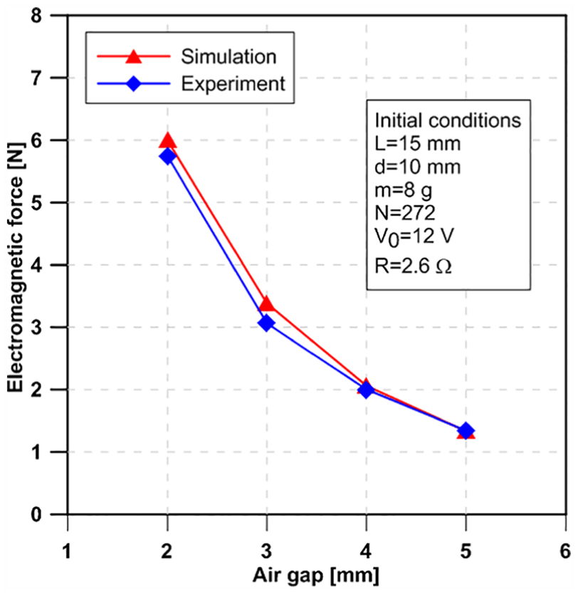
Electromagnetic force versus air gap.
The experimental results show that when the air gap increases from 2 to 5 mm, the electromagnetic force decreases quickly due to the decreased magnetic field strength. 1 This also agrees with simulation results, given that the difference between the simulation and experiment is not significant, as shown in Figure 18. The effects of input voltages on the plunger displacement are shown in Figure 19. The simulation and experimental results show that the plunger displacement increases rapidly when changing the input voltage from 10 to 14 V.

Plunger displacement versus time.
Conclusion
Operation of a solenoid used for natural gas injector was described by electrical and mechanical models. The solenoid injector was modeled and simulated using Maxwell and Simplorer. Effects of cross-sectional shape of the coil, plunger length, plunger diameter, gas pressure, spring stiffness, mass of plunger, and number of coil turns on the operating characteristics of the solenoid injector have been investigated. In addition, experimental systems were established to examine the electromagnetic force and the plunger displacement based on the effects of air gap and input voltage, respectively.
The simulation study indicated that a high-performance solenoid injector could be obtained if the key parameters such as cross-sectional shape of the coil, plunger length, plunger diameter, gas pressure, spring stiffness, mass of plunger, and number of coil turns were appropriately adjusted. It can be found that the electromagnetic force and displacement of the plunger could be increased faster by reducing the length and increasing the width of the cross-sectional shape of the coil. Furthermore, by increasing the length and diameter of the plunger, the electromagnetic force was increased significantly. The increase of the gas pressure should be carefully considered to avoid its influences for the electromagnetic force and plunger displacement. For the effects of plunger mass, the simulation study found that the plunger mass should not be higher than 8 g not only to avoid a fluctuation in plunger displacement but also to reduce the open and close response times. This provides useful knowledge for designing efficient injectors. The increase of spring stiffness could reduce the open and close response time; however, it also resulted in a lower gas flow rate. The reduction of coil turns was found as a benefit for decreasing the close response time; however, it also caused a slower motion of the plunger in the open stage. Finally, the simulation results were validated by experimental results on the effects of air gap and input voltage. The model-based and experimental studies provided useful information for designing a high-performance solenoid used for natural gas injector.
Footnotes
Handling Editor: ZW Zhong
Declaration of conflicting interests
The author(s) declared no potential conflicts of interest with respect to the research, authorship, and/or publication of this article.
Funding
The author(s) disclosed receipt of the following financial support for the research, authorship, and/or publication of this article: This work was supported by the Industrial Strategic technology development program (10053151, Development of the 800 kPa Fuel System of a High Pressure Precision Control for NGV) funded By the Ministry of Trade, Industry & Energy (MI, Korea). This work was also supported by Upbringing Business with Innovative Urban Public Institutions by the Ministry of Trade, Industry and Energy (MOTIE, Korea) [Project Name: Establishment of Battery/Ess-Based Energy Industry Innovation Ecosystem].