
Abstract
Multi-source drive system with the feature of compact, small size and other advantages is widely used in large engineering machinery, such as shield machine, wind turbines, and shearer. In this article, a reasonable power transmission form is designed and the electromechanical-hydraulic coupling model of the multi-source drive system including the hydraulic pump-motor lumped parameter model and gear system dynamics model is established based on the co-simulation of MATLAB and AMEsim. Taking the pump flow pulsation and the time-varying meshing stiffness as the external and internal excitation of the multi-source drive system, respectively, the vibration and the dynamic characteristics of the multi-source drive system and the transfer characteristics of the dynamic excitation are analyzed. Results show that the flow-speed pulsation and the pressure-torque pulsation are gradually reduced along the direction of the transmission chain. As the external and internal excitation, the flow pulsation and the time-varying meshing stiffness will cause complex influences on the vibration and the dynamic characteristics of the multi-source transmission system. The findings provide a reference basis for the design of the multi-source drive system.
Keywords
Introduction
Multi-source drive system with the feature of compact, small size and other advantages is widely used in shield machine, wind turbines, shearer, and so on. At present, research on multi-source drive system mainly focuses on the load sharing, synchronous control, and multi-stage separation of transmission system. Instead, research on the interaction of the coupling for multi-stage in the system is still relatively rare. For multi-source drive system, Jeftenić et al. 1 researched multi-motor synchronous control to improve the load sharing of system. Yang et al. established the coupled mechanical and electrical coupling dynamics model using the centralized parameter method and analyzed its dynamic load sharing characteristics. The results showed that the system non-uniform load characteristics can be improved by reducing the asynchrony of speed or increasing the load. 2 W Sun et al. 3 researched the inherent characteristics of a multi-source drive system. The flow and pressure pulsation of piston pump are the main causes of vibration and noise in the hydraulic system. Edge et al. 4 studied the effects of the inlet pressure on the flow fluctuation and the pressure changes in piston chamber. Yang et al. 5 established a piston pump flow pulsation model on complex conditions and analyzed the effects of the outlet pressure of the flow pulsation in steady-state and transient conditions. A Kahraman 6 analyzed the inherent and dynamic characteristics of planetary gear, and Zhao and Lan 7 established a dynamics model of the cutting transmission system and revealed the periodic vibration characteristics of the gear system caused by the stiffness excitation and the meshing impact. Guo 8 established a comprehensive model of shearer cutting unit based on the vibration theory, multibody dynamics, nonlinear finite element, and virtual prototyping technology, as well as revealed the response characteristic of the cutting unit in constant load and varying load conditions.
The electromechanical coupling effect is general in many fields, and there are some other scholars who have studied this phenomenon, especially for the motor-driven system, such as robots and space manipulator with harmonic drive. Liu et al. 9 proposed a coupled dynamic model of the motor-driven flexible manipulator system (MDFMS) and studied the vibration responses of the flexible manipulator under different velocities, accelerations, and structure parameters, as well as the effect mechanism of the driving motor on the vibration responses. Zhao et al. proposed a new method to analyze the dynamic reliability and parameter sensitivity of space manipulator with harmonic drive. The proposed method extends the previous response surface method (RSM) and focuses on the characteristics of the output dynamical property of the space manipulator. 10
However, many scholars only do a detailed analysis on the pump or gear transmission system and seldom analyze the effects of pump flow pulsation or time-varying mesh stiffness and both of them on the electromechanical-hydraulic coupling system. When the pump and multi-stage gear system are coupled together, new dynamic characteristics may be induced. As a result, most current dynamics studies of multi-source drive system are difficult to guide the design of this system. Based on the patents previously developed by the research group, 11 a coupling dynamic model of multi-source drive system, which is based on the driving of hydraulic pump, is established by conducting co-simulation of the MATLAB and AMEsim. This article analyzed the vibration and dynamic characteristics of the transmission system under the periodic excitation with respect to the pump pulsation and time-varying mesh stiffness, based on the electromechanical-hydraulic coupling model.
Principle and design of the electromechanical-hydraulic short cutting transmission system
Principle and design of the hydraulic drive circuit
An electromechanical-hydraulic multi-source drive system is proposed based on the transmission type of multi-pump and multi-motor in the shield machine hydraulic system.12,13 The proposed model offers many advantages over the conventional design. First, the deformation damage of the rocker arm due to overloading and strong shock can be avoided by substituting the long transmission chain system with the multi-pump and multi-motor hydraulic system. Second, the speed of the cutting roller can be adjusted by the volume speed-modulating circuit of variable displacement pump and constant displacement motor. Furthermore, the cutting roller can cut coal with reasonable cutting thickness and achieve the maximum cutting effectiveness. Overall, compared to the traditional long transmission chain system, the hydraulic system has a more desirable impact performance. Figure 1 shows the proposed multi-source drive/transmission system.
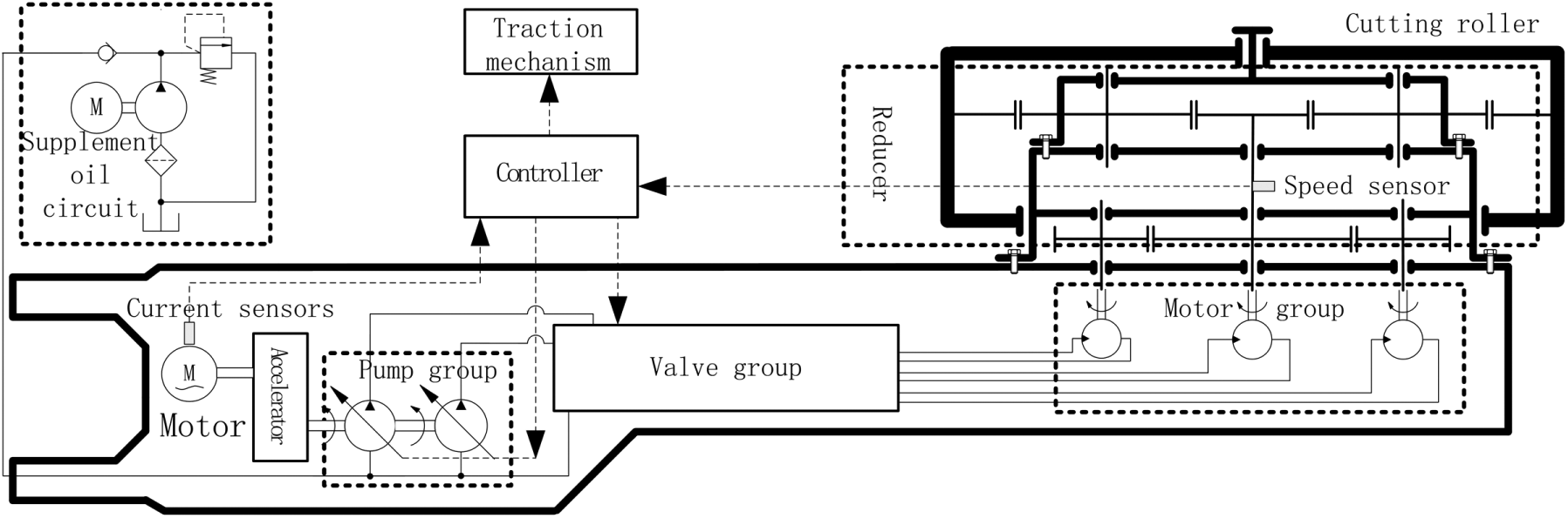
The multi-source drive system.
Figure 2 shows the hydraulic drive circuit schematic of short cutting transmission system. The speed of the constant displacement motor can be adjusted by changing the flow of pump 1 and pump 2. The spill valve is installed in the high-pressure oil circuit to avoid overload. The low-pressure oil circuit is equipped with a small flow supplement oil pump to supplement for the leaks of the variable pump and the hydraulic motor.

Schematic diagram of the hydraulic drive circuit.
Principle and design of the gear reduction system
The gear reduction system is the most important portion of the cutting unit and its system structure is shown in Figure 3. The coupling is used to connect the hydraulic motors and the pinions. The power of the large gear is transmitted to the sun gear and then from the ring gear to the roller after the second reduction. According to the parameters of the multi-source drive system, the total gear ratio of the gear reduction system is about 50, the coupling gear system ratio is set to be 9 initially, and the second planetary gear system ratio is set to be 5.56.
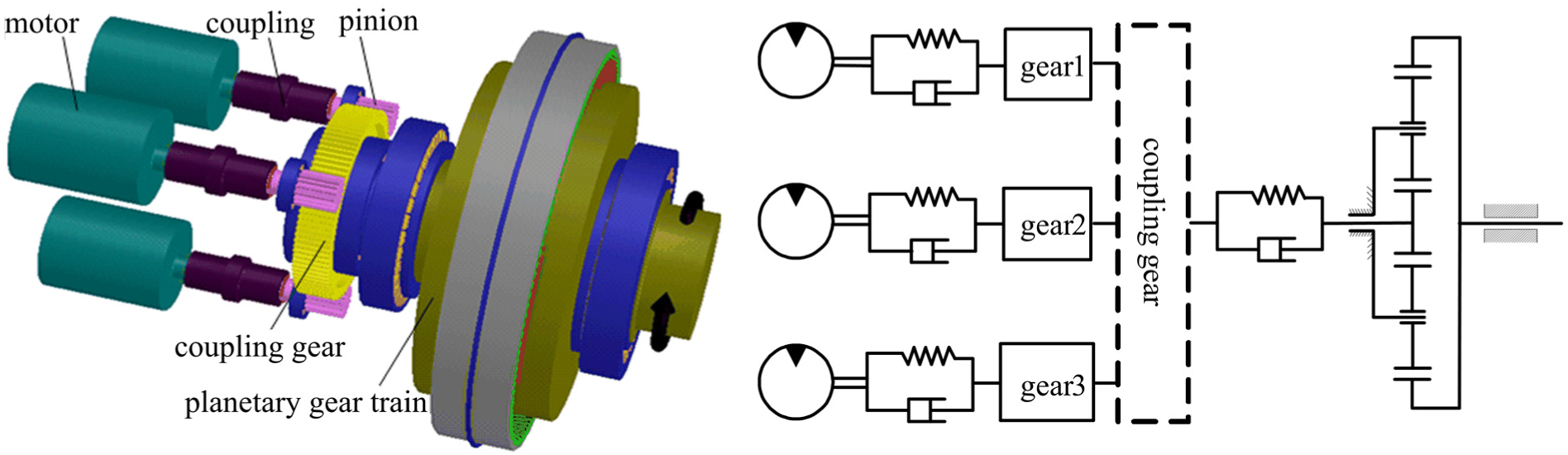
Structure of the gear reduction system.
As shown in Figure 3, the power is transmitted from the sun gear to the ring gear in the planetary gear system. The external and internal meshing are the two structural types of the coupling gear system, as shown in Figure 4. According to the external structure of the oblique shaft motor and the internal space limitations of the cutting unit, the structure type a is used in this article. The parameters of the coupling gear system and the planetary gear system are shown in Table 1.
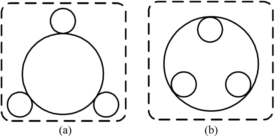
Structure type of the coupling gear system.
Parameters of the gear system.

Modeling of the electromechanical-hydraulic short cutting transmission system
Dynamics model of the coupling gear system
A dynamics model is the basis of dynamics equations. The equivalent dynamics model of the coupling gear system is shown in Figure 5.2,14,15

Dynamics model of the coupling gear system.
Three pinions are distributed in the circumferential direction uniformly and each gear unit is regarded as a rigid body of rotation with 3 degrees of freedom along the x direction, the y direction, and the rotational direction. The brace stiffness of the gear transmission shaft and the bearing, as well as the box body, is uniformly equivalent to the bearing stiffness. Here, rpi (i = 1, 2, 3) and rb are the base radii of the three pinions and the large gear, respectively; θpi and θb are the corresponding angular displacements; xpi, xb, ypi, and yb are the vibration displacements along x and y directions. Also, kxpi, kxb, kypi, and kyb are the equivalent brace stiffness of the pinions and the large gear in x and y directions; cxpi, cxb, cypi, and cyb are the equivalent damping of the pinions and the large gear in x and y directions; kpi and cpi are the meshing stiffness and the damping between the pinions and the large gear. φi are the angle distribution of the pinions, φi = 2π(i – 1)/3; αn is the pressure angle.
The parameter vector of the coupling gear system is set to be: X =[xp1, xp2, xp3, xb, yp1, yp2, yp3, yb, θp1, θp2, θp3, θb] and then the differential equation of the motion for the coupling gear system is established

In equation (1), mpi (i = 1, 2, 3) and mb are the mass of the three pinions and the large gear, respectively; Ipi and Ib are the inertia of the pinions and the large gear, respectively; Fpi is the meshing force between the pinions and the large gear. The meshing force can be calculated directly by the following formula without considering the meshing error

In equation (2), λn = αn + φi. Combining equations (1) and (2), the differential equations of the system can be written by a standard matrix equation

Dynamics model of the planetary gear system
The dynamics model of the planetary gear system with 6 degrees of freedom is shown in Figure 6. 16
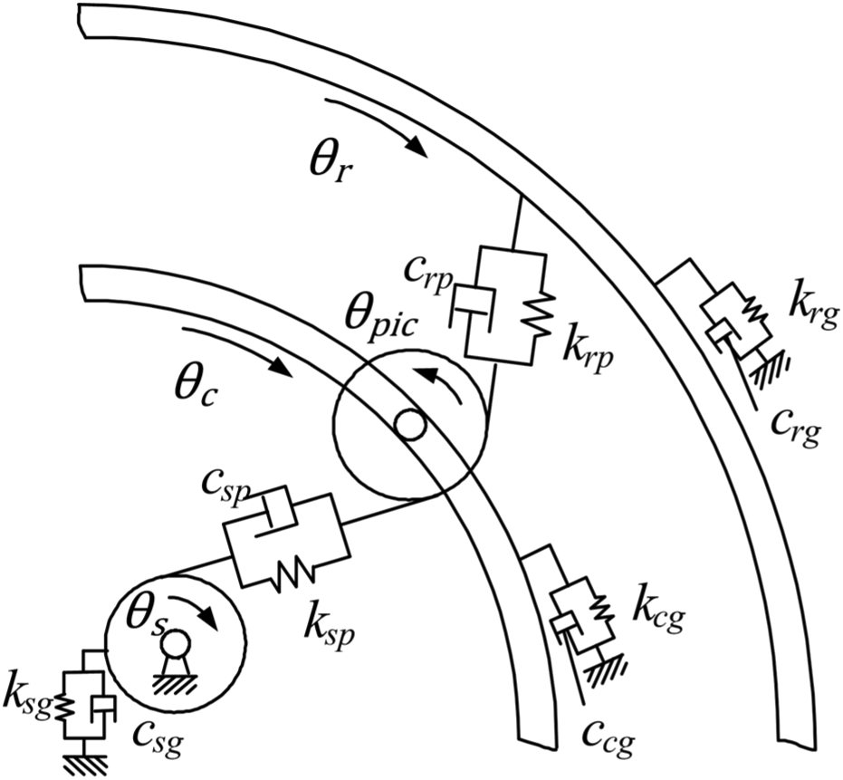
Dynamics model of the planetary gear system.
The dynamics equations of the planetary gear system can be written as

In equation (4), θs, θpj (j = 1, 2, 3), θc, and θr are the angular displacements of the sun gear, the planetary gear, the planet carrier, and the ring gear, respectively; θc = 0; rs, rp, and rr are the base radii of the sun gear, the planetary gear, and the ring gear, respectively; rc is the rotation radii of the planet carrier center; Is, Ip, and Ir are the inertia of the sun gear, the planetary gear, and the ring gear, respectively;
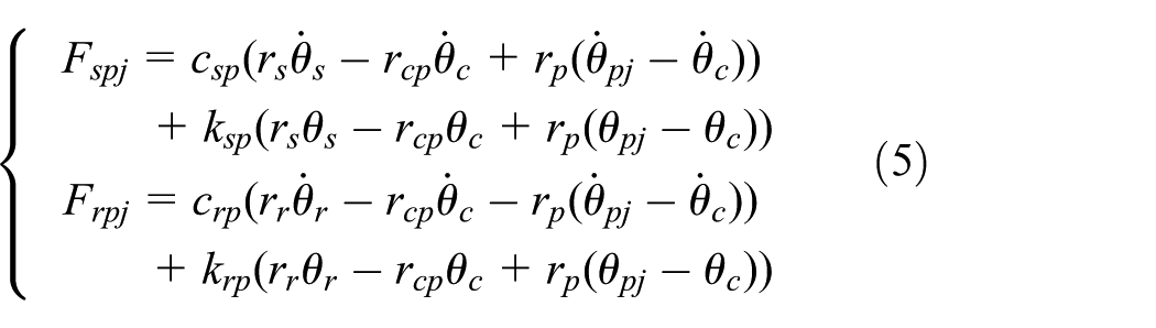
In equation (5), csp and ksp are the meshing damping and the stiffness between the sun gear and the planetary gear; crp and krp are the meshing damping and the stiffness between the planetary gear and the ring gear.
Calculation of the time-varying meshing stiffness
Stiffness excitation is a dynamic excitation caused by the time variation of composite stiffness in the gear meshing process, and it is also one of the most important dynamic excitation forms in the gear transmission system. 17 The coincidence degree is typically greater than 1 in the gear meshing process, and the alternating meshing phenomenon of the single and double teeth will appear in the gear meshing process with the change of meshing point. As shown in Figure 7, the time-varying meshing stiffness is externalized by a periodic similar rectangular wave function in this article.

Periodic variation of the meshing stiffness.
In Figure 7, k1 is the meshing stiffness of the single pair gear teeth, which is also the minimum meshing stiffness; k2 is the meshing stiffness of the double pair gear teeth, which is also the maximum meshing stiffness. Taking the planetary gear system as an example, the meshing frequency based on the movement of the planetary gear system is calculated as follows when the ring gear is fixed

In equation (6), ns is the speed of the sun gear; zs is the number of the sun gear teeth; zr is the number of the ring gear teeth. The time-varying meshing cycle of the gear is given in equation (7)

The time-varying meshing stiffness based on the Fourier series without the higher-order terms of the meshing frequency is expressed in equation (8)

In equation (8), ks is the average meshing stiffness, ks = (2 – ε)k1 + (ε – 1)k2; bm is the mth harmonic amplitude, bm = 2(k2 – k1)sin(mπ(ε – 1))/mπ; ε is the coincidence degree; and t0 is the initial phase of meshing. B is the conjugate complex of the previous one.
Combining the gear parameters of the planetary gear system in Table 1, the average meshing stiffness ks of the coupling gear system, the meshing stiffness k1 of the single pair gear teeth, and the meshing stiffness k2 of the double pair gear teeth can be calculated. The time-varying meshing stiffness of the coupling gear system and the planetary gear system are shown in Figures 8–10.

Time-varying meshing stiffness of the coupling gear.

Time-varying meshing stiffness between the sun gear and the planetary gear.

Time-varying meshing stiffness between the planetary gear and the ring gear.
Lumped parameter model of the hydraulic pump and motor
A single plunger model is established in AMESim, which is shown in Figure 11. Here, 1 is the oil inlet, 2 is the oil outlet, 3 is the displacement control signal port, and 4 is the plunger speed input port. The lumped parameter model of the pump with nine plungers is established based on the single plunger model, and it is shown in Figure 12. 18
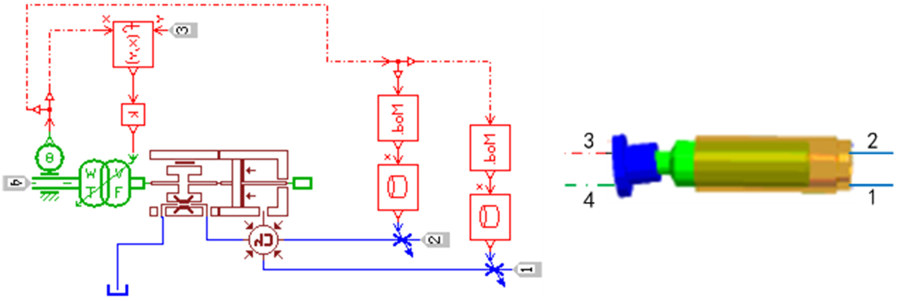
Single plunger model.
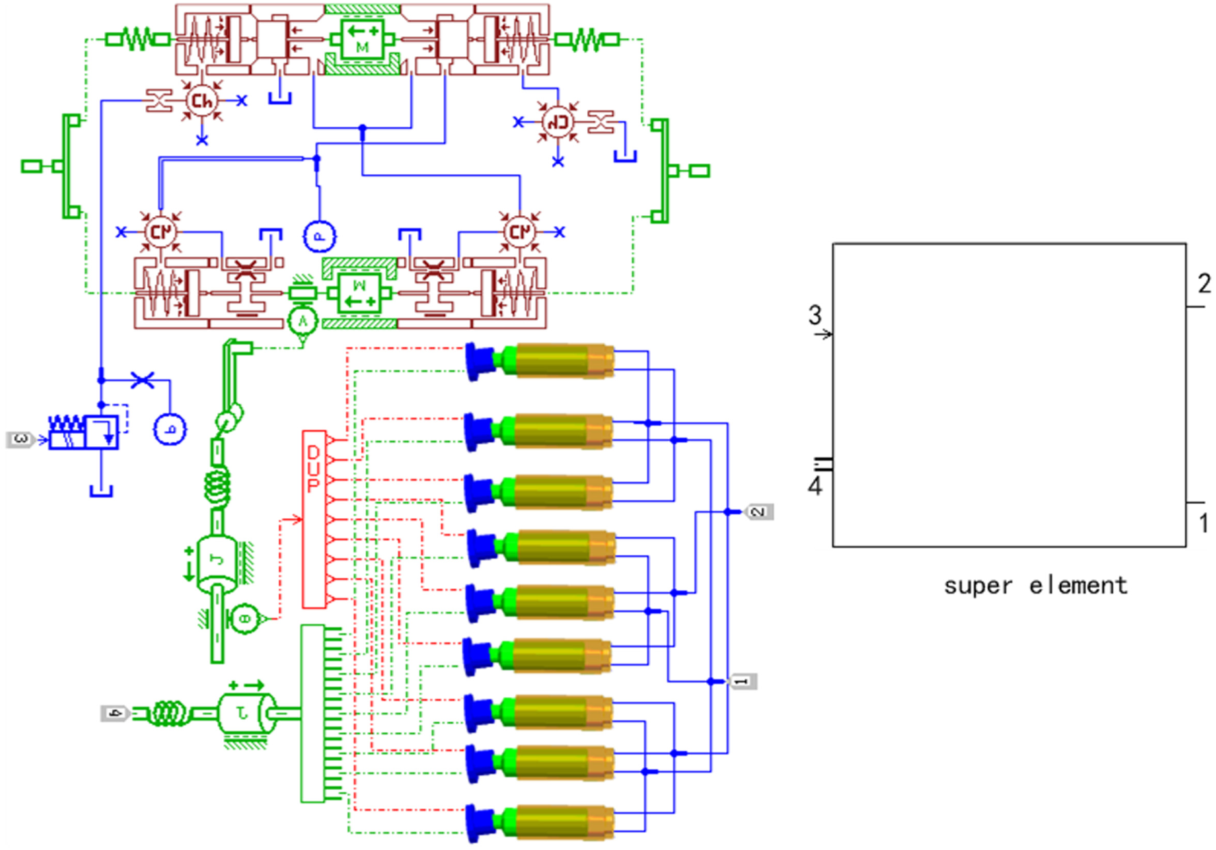
Multi-plunger hydraulic pump model.
The lumped parameter model of the motor is established by the same method. The pulsation rate δA of one variable parameter at the time period of [t1, t2] is

In equation (9), Amax is the instantaneous maximum value of the variable, Amin is the instantaneous minimum value of the variable, and At is the average value of the variable.
Electromechanical-hydraulic coupling model of the short cutting system
As shown in Figure 13, the electromechanical-hydraulic coupling model of the cutting system is established according to the schematic diagram of the system and the various subcomponent models. In Figure 13, qp1, qp2, qp, qm1, qm2, and qm3 are the outlet flow of pump 1, the outlet flow of pump 2 outlet, the total outlet flow, the inlet flow of motor 1, the inlet flow of motor 2, and the inlet flow of motor 3, respectively; pp, pm1, pm2, pm3, and pr are the pressure of the pumps, the inlet pressure of motor 1, the inlet pressure of motor 2, the inlet pressure of motor 3, and the pressure of the low-pressure oil circuit, respectively. θm1, θm2, θm3, θp1, θp2, θp3, θb, θs, θr, and θd are the angular displacements of motor 1, motor 2, motor 3, pinion 1, pinion 2, pinion 3, the large gear, the sun gear, the ring gear, and the roller, respectively. Im1, Im2, Im3, Ip1, Ip2, Ip3, Ib, Is, Ir, and Id are the rotational inertia of motor 1, motor 2, motor 3, pinion 1, pinion 2, pinion 3, the large gear, the sun gear, the ring gear, and the roller, respectively. Similarly, km1, km2, km3, kb, and kd are the torsional stiffness between motor 1 and pinion 1, motor 2 and pinion 2, motor 3 and pinion 3, the sun gear and the large gear, and the ring gear and the roller, respectively; cm1, cm2, cm3, cb, and cd are the corresponding torsional damping values.
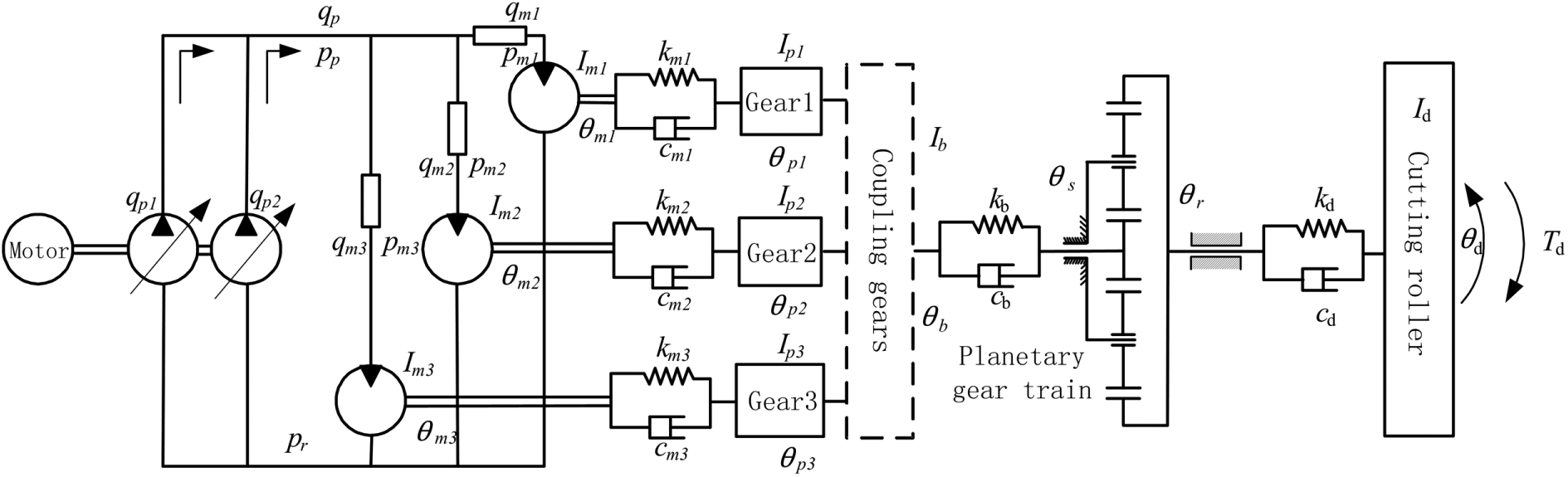
The multi-source drive system model.
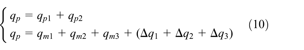
The flow loss and the pressure loss of the oil circuit are assumed to be Δq1, Δq2, Δq3, Δp1, Δp2, and Δp3, respectively, and the flow equation of the system is as follows 19
The pressure equation of the system is as follows

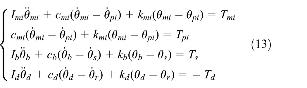
The continuity flow equation and the torque balance equation of the motor are as follows

The dynamics equations of the gear transmission system are as follows
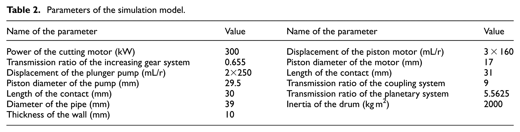
As shown in Figure 14, the simulation model of the short cutting transmission system is established by combining the schematic diagram and the theoretical model. The model of the hydraulic transmission system is established in AMESim, the model of the coupling gear system and the planetary gear system is established in MATLAB, and then the co-simulation model of the cutting transmission system is established in AMESim. The plunger pump and the piston motor are used instead of the super elements, the hydraulic pipe is modeled as a constant friction damping model, and the effects of valves in the hydraulic transmission system are ignored. The parameters of the simulation model are shown in Table 2.

Simulation model of the multi-source drive system.
Parameters of the simulation model.
Analysis of the characteristics of the cutting transmission system based on the periodic dynamic excitation
Analysis of the vibration characteristics of the system based on the flow pulsation
In order to analyze the specific vibration characteristics of the cutting transmission system prominently when the flow pulsation is the external excitation, the meshing stiffness of the coupling gear system and planetary gear system are fixed. The load torque of roller is Td = 50,000 N m, the simulation time is set at 1.5 s, and the simulation step is set at 10−5 s. Then, the pump flow pulsation, the motor speed pulsation, and the torque pulsation are obtained, and they are shown in Figures 15–17.

Pump outlet flow.

Motor output speed.
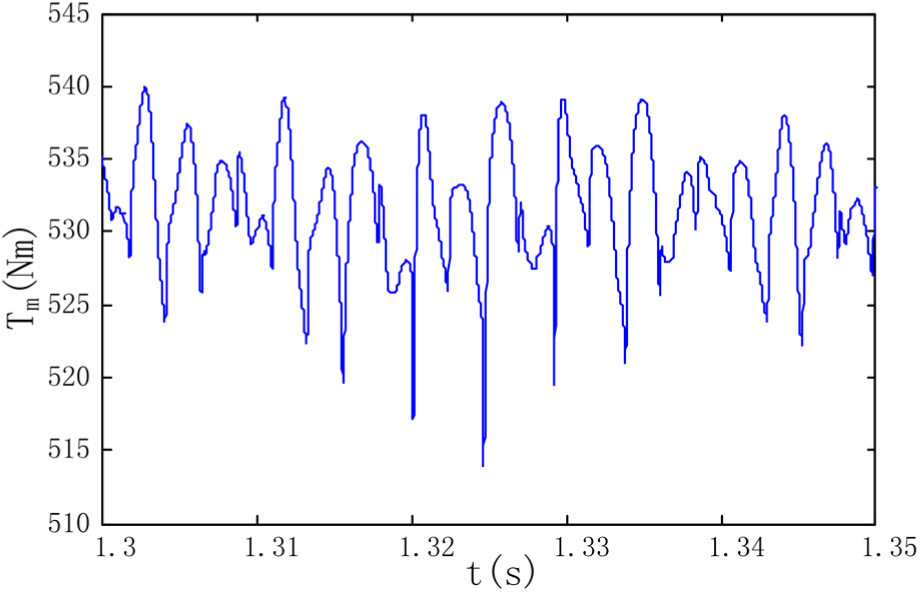
Motor output torque.
It can be seen from the figure that the output flow of the pump fluctuates on 400 L/min periodically, and the average flow pulsation rate is about 17.33%. In addition, the output speed of the hydraulic motor follows the outlet flow of the pump and the speed fluctuation amplitude changes more. The torque fluctuation amplitude of the motor changes non-uniformly and the pulsation rate is 4.8%. Overall, because of the periodic motion of the pump and the motor plungers, its effects on the hydraulic system are seen as the flow pulsation and its effects on the power components are seen as the torque pulsation.
The output torque of the motor is input to the pinions of the coupling gear system by three couplings and the torque pulsation is a kind of external excitation to the coupling gear system. The vibration displacement, the acceleration, and the meshing force between the pinion and the large gear are shown in Figures 18–20. It can be seen from Figures 18 and 20 that the vibration displacement and dynamic meshing force of the pinion present the same variation tendency as the output torque of the pump in Figure 17.
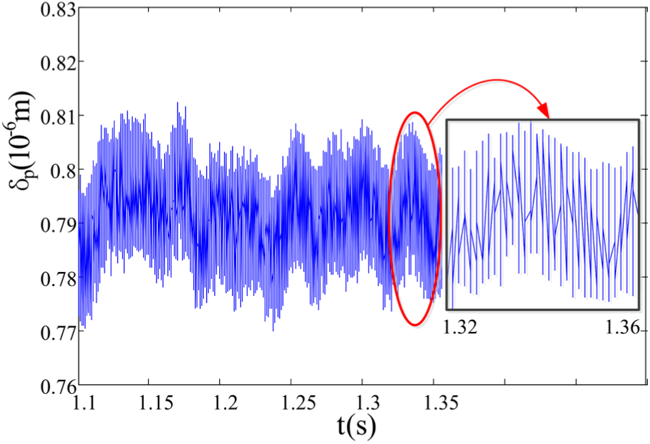
Vibration displacement of the pinion.

Vibration acceleration of the pinion.
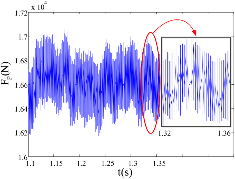
Dynamic meshing force between the pinion and the gear.
The displacement of the pinion along the meshing line vibrates close to 0.79 × 10⁻³ mm, and the vibration trend is similar to the input torque of the motor. It can be seen from Figure 19 that the acceleration vibration of the pinion caused by the input torque pulsation is severe and has a high frequency. The changing trend of the dynamic meshing force is almost the same as the changing trend of the vibration displacement between the pinion and the large gear.
The pump, the hydraulic circuit outlet, the motor, the coupling gear system, and the planetary gear system are selected to be the five monitoring sites in the short cutting transmission system, respectively. Td = 75,000 N m, Td = 50,000 N m, and Td = 25,000 N m are the three different load conditions. The variables qp1 and qm1 reflect the flow of the pump and the motor; the variables ωm1, ωp1, and ωr reflect the speed of the motor, the pinion, and the ring gear. The variables in the different load conditions are shown in Figure 21.
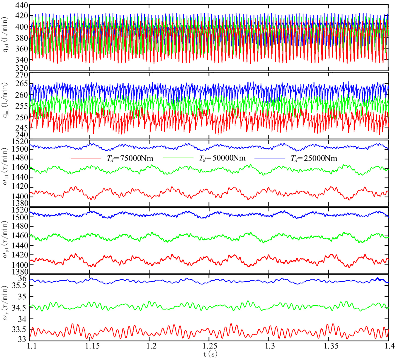
Flow and speed pulsation in the different load conditions.
The variable pp1 reflects the outlet pressure of the pump; the variable pm1 reflects the inlet pressure of the motor; the variables Tm1, Tp1, and Tr reflect the torque of the motor, the pinion, and the ring gear, respectively. The variables are shown in Figure 22 under a roller load of 75,000 N m. The average pulsation rate of each reference point at the time period of T = 1.1–1.2 s in the different load conditions is shown in Table 3.

Pressure and torque pulsation of each reference point.
Average pulsation rate of each monitoring site in the three load conditions.

It can be seen from Table 3 and Figures 23 and 24 that the greater the roller load, the greater the flow and speed pulsation, but the pressure and torque pulsation will become smaller. In case of the flow and speed, the pulsation rate of each reference point is gradually reduced along the power transmission direction. The torque pulsation is also gradually reduced along the direction of transmission chain. In general, the flow pulsation excitation is gradually reduced along the direction of transmission chain.
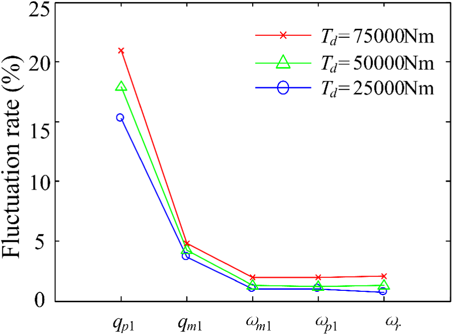
Flow and speed pulsation rate.

Pressure and torque pulsation rate.
Analysis of the dynamic characteristics of the system based on the periodic excitation
The simulation condition is set as follows: the load of the roller increases from Td = 50,000 N m to Td = 85,000 N m at 1.5 s. When only considering the time-varying meshing stiffness excitation or considering both the time-varying meshing stiffness excitation and the flow pulsation excitation, the fluctuations of the flow, the pressure, and the dynamic meshing force between the sun-planet gear pair are shown in Figures 25–27, respectively. It is observed from the figures that the pump flow pulsation will increase the fluctuations of the system greatly as the external excitation.

Flow of the system: (a) time-varying meshing stiffness + flow pulsation and (b) time-varying meshing stiffness.
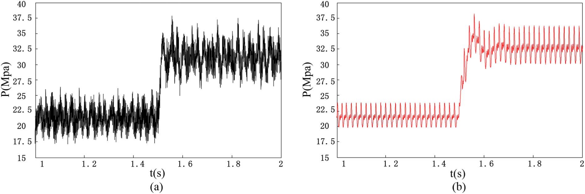
Pressure of the system: (a) time-varying meshing stiffness + flow pulsation and (b) time-varying meshing stiffness.

Dynamic meshing force of the sun-planet gear pair: (a) time-varying meshing stiffness + flow pulsation and (b) time-varying meshing stiffness.
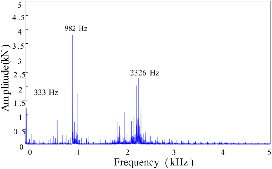
In order to analyze the dynamic characteristics of the system further, the flow of the pump, the time-varying meshing stiffness, the torque of the motor, and the dynamic meshing force were analyzed on frequency domain by Fast Fourier Transformation (FFT). The results are shown in Figures 28–31. It can be seen from Figure 29 that the frequency distribution of the time-varying meshing stiffness is very regular, which is mainly composed of the fundamental frequency and is double the frequency. It can be seen from Figure 28 that the flow pulsation main frequencies are 333, 982, and 2326 Hz. The 982 and 2326 Hz are the triple and the seven times that of this frequency, respectively. Similarly, these frequencies can also be seen in the motor torque. Figure 31 shows that frequency spectrum of the dynamic meshing force is mainly composed of 333, 982, 2326 Hz, and the frequency near them, which are also the same as the main frequency components of the frequency spectrum of the flow. It is observed from the frequency spectrum figures that the pump flow pulsation is the main cause which affects the dynamic characteristics of the system, and as the internal excitation, the time-varying meshing stiffness will cause additional effects on this basis.

Frequency spectrum of the flow.

Frequency spectrum of the varying meshing stiffness.

Frequency spectrum of the motor torque.
Frequency spectrum of the dynamic meshing force.
Conclusion
This study is based on a new power transmission system with electromechanical-hydraulic multi-source drive, which is proposed by our research group. The electromechanical-hydraulic coupling model of the cutting transmission system is established by the proposed system, and then, the vibration and the dynamic characteristics of the cutting transmission system are analyzed based on the pump flow pulsation and the time-varying meshing stiffness.
The flow pulsation of the plunger pump is transformed into the torque pulsation through the hydraulic motor, which has a significant effect on the vibration characteristics of the coupling gear system. The effects of the flow pulsation on the dynamic characteristics of the gear system are gradually reduced along the power transmission direction. It is also found that the greater the external load, the greater the flow and speed pulsation of the system, and, at the same time, the smaller the pressure and torque pulsation of the system.
In general, the pump flow pulsation is the main cause that affects the dynamic characteristics of the system, and as the internal excitation, the time-varying meshing stiffness will cause additional effects on this basis.
Footnotes
Handling Editor: Shun-Peng Zhu
Declaration of conflicting interests
The author(s) declared no potential conflicts of interest with respect to the research, authorship, and/or publication of this article.
Funding
The author(s) disclosed receipt of the following financial support for the research, authorship, and/or publication of this article: This work was supported by the State Key Development Program of Basic Research of China (2014CB046304) and the Project No. 2018CDJDCD0001 supported by the Fundamental Research Funds for the Central Universities.