
Abstract
This article presents experimental and numerical studies on the shear behavior of reinforced concrete beams pre-stressed with carbon fiber reinforced polymer tendons. A total of 23 beams were tested to analyze the failure mode and shear performance of pre-stressed concrete beams. Experimental results revealed that there were two typical shear failure modes, that is, shear compression failure and inclined compression failure. Next, the experimental and numerical results were used to explore factors influencing the failure mode and the shear behavior of the concrete beams, including the type of pre-stressing tendons, stirrup ratio, shear span–depth ratio, number of pre-stressing tendons, and their initial pretension levels. It is demonstrated that shear span–depth ratio and stirrup ratio are the two main determinants of the failure mode and shear capacity of the concrete beams pre-stressed with carbon fiber reinforced polymer tendons. However, the bonding conditions of the pre-stressing carbon fiber reinforced polymer tendons have no significant effect on the shear capacity of the pre-stressed concrete beam.
Keywords
Introduction
Fiber reinforced polymer (FRP) tendons can be substituted for steel reinforcements or pre-stressing cables in engineering projects and have been extensively studied. FRP reinforcement, specifically carbon fiber reinforced polymer (CFRP) reinforcement, has desirable properties such as anti-corrosion, light weight, high strength and being non-magnetic. Nevertheless, FRP tendons also have some disadvantages for civil engineering projects, such as their relatively low transverse strength, non-plastic behavior, high cost, and susceptibility to stress rupture. Of the above disadvantages, low transverse strength and lack of plastic behavior are critical to the shear capacity of concrete members with FRP tendons.
There is extensive literature on concrete structures reinforced with FRP tendons that focuses on their flexural members.1–4 Unlike the flexural behavior, the shear performance of concrete structures is fairly complex even for conventionally reinforced or pre-stressed members. There is also some research on shear performance of reinforced concrete beams with non-prestressed FRP tendons.5–9 However, the shear behavior of concrete beams pre-stressed with FRP tendons is different from those with non-prestressed FRP reinforcements. Increasing pre-stressing forces have a considerable impact on the failure mode and ultimate capacity of concrete beams pre-stressed with FRP tendons compared to those with non-prestressed FRP reinforcements. 10 Due to the lack of sufficient shear test data available at present, the shear performance of pre-stressed beams with FRP tendons has not been fully investigated. Yonekura et al. 11 concluded that the pre-stressing force can effectively increase the shear capacity of concrete beams pre-stressed with FRP tendons. Tottori and Wakui 12 determined that the shear capacity of pre-stressed concrete beams was not affected by the type of pre-stressing tendons. The composite action of a bridge deck with pre-stressing CFRP tendons and shear reinforcements was simulated by Fam et al. 13 Park and Naaman14,15 studied the dowel action of pre-stressed FRP tendons and the shear behavior of pre-stressed concrete beams. The tests showed that premature failure is likely to occur in FRP pre-stressed concrete beams due to shear tendon rupture, which results in reduced ultimate capacity. Grace et al. 16 tested six box beams to investigate the shear behavior of beams with pre-stressed CFRP tendons. The shear behavior of FRP pre-stressed concrete beams with continuous FRP helical stirrups was described by Whitehead and Ibell. 17 Shear tests on conventionally reinforced beams and pre-stressed concrete beams were carried out in the study. Martin et al. 18 tested six one-way slabs to investigate the flexural performance of glass fiber reinforced polymer (GFRP) reinforced slabs with pre-stressed CFRP tendons. The test results showed that slabs without shear reinforcements failed in shear in a brittle manner, while their ultimate flexural capacities were not reached. Martin and Khaled 19 also conducted a shear test of concrete slabs with post-tensioned FRP tendons under static or fatigue loading.
To predict the complex shear behavior of concrete beams, refined analytical and numerical models have been developed. 10 However, the shear capacity of pre-stressed concrete beams with FRP tendons is still an open topic; there is no universally accepted simplified design formulation. Attempts to achieve such a formulation have been made by some researchers. Whitehead and Ibell 20 developed a rational approach to explore the shear capacity of FRP pre-stressed and conventionally reinforced concrete beams. Yasuhiko et al. 21 presented a non-linear finite element (FE) analysis to clarify the shear resisting performance of concrete beams pre-stressed with FRP rods.
With respect to the shear behavior of concrete beams pre-stressed with FRP tendons, the failure modes and effects of various factors are still uncertain. A simplified model for daily engineering practice has also not been developed. To investigate the shear performance of concrete beams pre-stressed with FRP tendons, experimental work and simple numerical models are needed.
This article presents a study that investigates the shear performance of concrete beams pre-stressed with CFRP tendons. In total, 23 concrete beams were tested until failure under concentrated loads. Numerical investigation using the FE software package ANSYS was also carried out. The failure modes and effects of various factors such as type of pre-stressing tendons, stirrup ratio, shear span–depth ratio, number of pre-stressing tendons, and pre-stressing levels on the shear performance of pre-stressed concrete beams with CFRP tendons were investigated in detail through experimental and numerical investigations.
Experimental program
Design of the specimens
The experiment explores the shear failure modes of concrete beams pre-stressed with CFRP tendons. Dimensions and reinforcements of the pre-stressed concrete beams are shown in Figure 1.
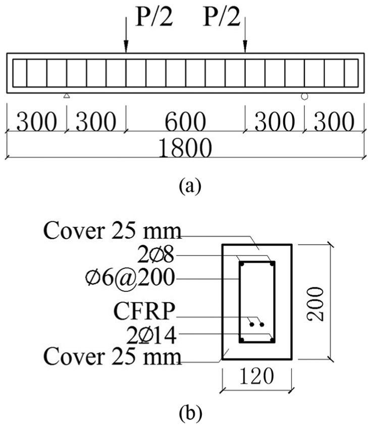
Reinforcements of the concrete beams (mm): (a) dimensions of the specimen and (b) configurations of the reinforcement.
Each concrete beam has a cross-section of 120 mm × 200 mm and a total length of 1800 mm. Like the steel cables, the CFRP tendons were set 60 mm from the bottom of the beam. The concrete cover for the steel reinforcements is 25 mm. The effects of parameters such as the type of pre-stressing tendons, stirrup ratio, shear span–depth ratio, number of pre-stressing tendons, and pre-stressing levels on the shear behavior of concrete can be evaluated by the tests. The selected shear span–depth ratio in the test was based on the results of other studies.22–25 The experimental program consists of three groups of tests. Group 1 consists of non-reinforced concrete beams. All beams in Group 2 and Group 3 are reinforced longitudinally with a total of four non-prestressed steel reinforcements. Two of these steel reinforcements, which are 14 mm in diameter each, are located at the bottom of the beams, while the other two, which are 8 mm in diameter, are set at the top. The diameter of the shear reinforcement is 6 mm. The detailed parameters proposed for each test series are summarized in Tables 1–3.
Detailed list of the first group without steel stirrups.

CFRP: carbon fiber reinforced polymer.
Detailed list of the second group with steel stirrups.

CFRP: carbon fiber reinforced polymer.
Detailed list of the third group with steel stirrups.

CFRP: carbon fiber reinforced polymer.
Material properties
Concrete beams were made in two batches at different places. The pre-stressing tendons of three specimen groups, including CFRP tendons and steel cables, were similar. The material properties of the steel reinforcements, CFRP tendons, and steel cables are presented in Table 4. The tensile strength of the steel reinforcements consisted of yield strength and ultimate strength, while that of CFRP tendons and steel cables only consisted of ultimate strength. For the concrete, Group 1 and Group 2 beam specimens were cast in the same batch and Group 3 was cast in the other batch. For the two batches, because they were obtained from different sources, there are some discrepancies between the properties of the steel reinforcements and concrete. For the first batch, the average compressive strength of the cube concrete was 27.02 MPa, while that of the other batch was 36.80 MPa. Three cubic concrete specimens (150 × 150 × 150 mm3) were tested while testing each batch.
Mechanical properties of reinforcements.

CFRP: carbon fiber reinforced polymer.
-1 denotes the first batch and -2 denotes the second batch.
Pre-stressing procedure
Concrete beams were pre-stressed using 8-mm CFRP tendons or 9.5-mm steel cables 1 month after casting, and then the metal ducts were grouted with a grout mixture to ensure effective bonding between concrete and steel cables or CFRP tendons. Three cubic mortar specimens (70.7 × 70.7 × 70.7 mm3) were tested on the 28th day after grouting. The average compressive strength of all grout mixtures was 42.1 MPa. All CFRP tendons were linearly placed on the beams through the metal ducts. The pre-stressing forces during the post-tensioning and testing were all measured by strain gauges attached to CFRP tendons. The pre-stressing loss of CFRP tendons is given in detail in Wang et al. 26 The pre-stressing forces of steel cables were measured by the load cells at the end of the steel cable anchorage.
Instrumentation
Electrical strain gauges were attached to the longitudinally oriented steel and CFRP tendons. The strain values in the steel and CFRP tendons were measured using these strain gauges. As shown in Figure 2, the concrete strain gauges are set on the side and top surface of the concrete beams between the two concentrated load points. Stain gauges are also glued on the side surface of the concrete and shear reinforcements between supports and load points. The deflection of concrete beams during testing is measured using linear voltage displacement transducers (LVDTs) at the middle and supports of the concrete beam.

Layout of the measuring points.
The load cells, LVDTs, and strain gauges were connected to the same data logger, and the results of the data were recorded automatically. Crack formation and growth of the specimens at each load step were observed and marked.
Testing procedure
The concrete beam was simply supported on two rollers under the steel plates in each test. Two symmetrical concentrated loads were exerted on the test beam symmetrically via a steel beam connected to a 20-ton hydraulic jack, as shown in Figure 3.
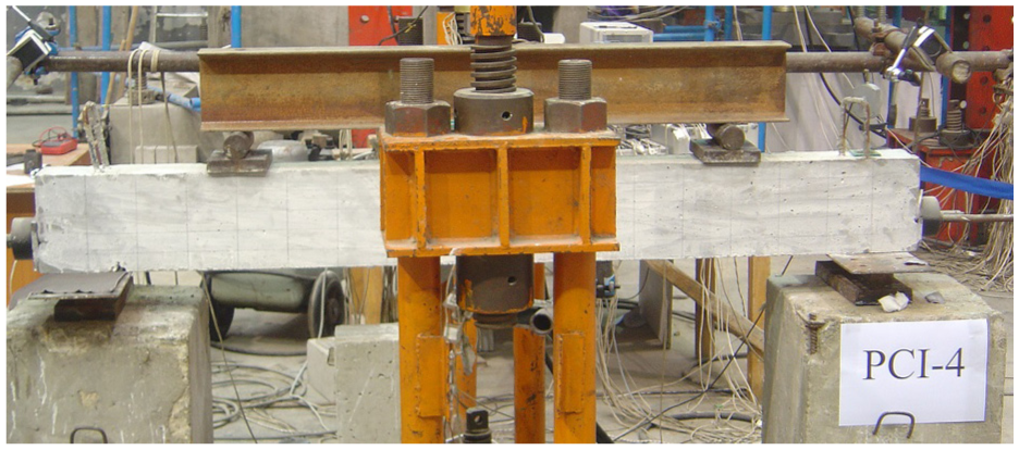
Set-up of the test.
Loads were applied in increments of 5 kN monotonically until failure. All measurements were recorded at each load increment during the loading stage.
Test results and discussion
During the test, there was no slippage of steel cables or CFRP tendons at the end of beams. The first cracks in the concrete beams were vertical cracks in the pure bending zone. The main results of the test are summarized in Table 5.
Main test results of pre-stressed concrete beams.
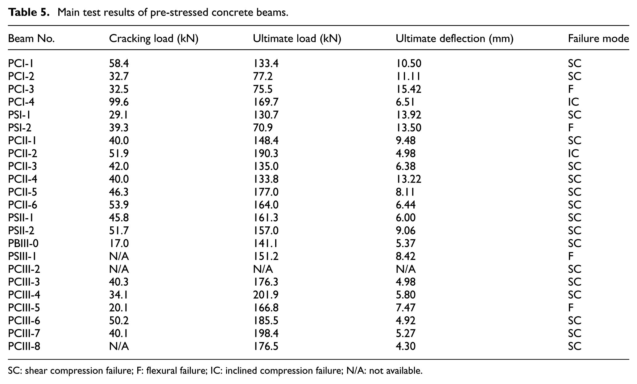
SC: shear compression failure; F: flexural failure; IC: inclined compression failure; N/A: not available.
Failure modes
During the test, none of the CFRP tendons were broken by shear force, even for the pre-stressed beams without stirrups. Three typical failure modes of the concrete beams pre-stressed with CFRP tendons were observed in the tests, that is, flexural failure, shear compression failure, and inclined compression failure. Among all the factors, shear span–depth ratio a/d was found to be the most important factor for determining the failure modes of the pre-stressed concrete beams, where a is the distance from the concentrated load to the reaction and d is the distance from the center of the tensile reinforcing steels to the top of the concrete beam. For Group 1, which consisted of beam specimens without steel stirrups, the beam would fail by inclined compression of the concrete, such as in beam PCI-5, when a/d was less than 1.0. Inclined cracks were initiated at the web of the concrete beam between the supports and loading point. The inclined cracks were parallel to each other. The inclined failure of the pre-stressed concrete beams was observed by the crushing of concrete between major diagonal cracks. When a/d was greater than 2.5, the pre-stressed concrete beams would undergo flexural failure. The concrete in the pure bending zone of the beams was crushed in compression. When 1 < a/d < 2.5, the concrete beams would fail in shear compression. There was only one main critical crack with maximum width and length. When the concrete on the top of the critical crack was crushed in the shear compression zone, the concrete beam failed. The main failure modes of CFRP pre-stressed beams with no stirrups are shown in Figure 4.
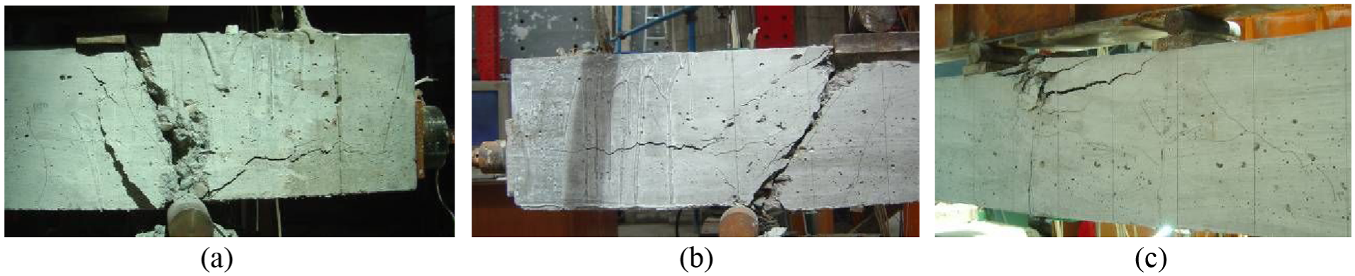
Failure modes of CFRP pre-stressed concrete beams with no stirrups: (a) inclined compression failure, (b) shear compression failure, and (c) flexural failure.
For the pre-stressed beams with steel stirrups, when the shear span–depth ratio a/d was less than 1.3, the beam would fail due to inclined compression of the concrete; when 1.3 < a/d < 2.6, the beam would fail due to shear compression; when m was greater than 2.6, flexural failure would occur for the pre-stressed beams. The failure modes of CFRP pre-stressed concrete beams with steel stirrups are shown in Figure 5.

Failure modes of CFRP pre-stressed concrete beams with steel stirrups: (a) inclined compression failure, (b) shear compression failure, and (c) flexural failure.
Effect of different types of pre-stressing tendons
There was a marked difference in the shear capacity of the test beams pre-stressed with different types of tendons. For example, for the unbonded pre-stressed beams with the same configurations, except for the type of the pre-stressing reinforcements, beam PCI-2 pre-stressed with CFRP tendons has an approximately 41% lower shear capacity than beam PSI-1 pre-stressed with steel cables, and beam PCII-3 has an approximately 16% lower shear strength than beam PSII-1. Because the elastic modulus of FRP reinforcement is relatively lower than that of steel, concrete beams pre-stressed with FRP rods may develop deeper and wider cracks than beams pre-stressed with steel. Deeper cracks lead to a smaller depth of uncracked concrete, which decreases the contribution of concrete to shear strength. Wider cracks would decrease the aggregate interlock and the residual tensile stresses affecting the shear strength. In addition, the contribution of the dowel action of FRP tendons can be small compared to that of steel. Eventually, the overall shear capacity of beams pre-stressed with CFRP tendons is lower than that of the pre-stressed concrete beams with steel cables.
For the unbonded pre-stressed beams, different types of pre-stressing tendons result in different failure modes. The failure mode of PSIII-1 pre-stressed with steel cables is flexural failure, while that of PCIII-3 pre-stressed with CFRP tendons is shear compression failure. The load–deflection relationships of the concrete beams pre-stressed with different tendons are shown in Figure 6.

Comparison of the shear behavior of different pre-stressing tendons: (a) pre-stressed beams without stirrups, (b) bonded pre-stressed beams with steel stirrups, and (c) unbonded pre-stressed beams with steel stirrups.
Effect of various bonding conditions of pre-stressing tendons
The effect of various bonding conditions of the pre-stressing tendons on shear behavior is presented in Figure 7. The bonded condition is shown to improve the shear capacity of the pre-stressed concrete beam to some extent. The shear strength of the bonded pre-stressed concrete beam with steel cables (PSII-1) is approximately 3% higher than that of the unbonded pre-stressed beam (PSII-2). For the pre-stressed concrete beams with CFRP tendons, the shear capacity of the bonded beam (PCIII-3) is approximately 15% higher than that of the unbonded beam (PCIII-4). The shear capacity of concrete beams can be improved by the pre-stressing technology. The shear capacity values of pre-stressed concrete beams PCIII-3 and PCIII-4 are higher than that of non-prestressed concrete beam PBIII-0.

Comparison of the effects of different bonding conditions of pre-stressing tendons on the shear capacity of the concrete beams: (a) beams pre-stressed with steel cables and (b) beams pre-stressed with CFRP tendons.
Effect of shear span–depth ratio
The shear span–depth ratio not only affects the failure modes of the pre-stressed concrete beams but also has an important effect on the shear capacity. Figure 8 shows the influence of the shear span–depth ratio on the shear capacity of pre-stressed concrete beams. When the shear span–depth ratio of pre-stressed concrete beams without stirrups is less than 1.0 and that of pre-stressed concrete beams with steel stirrups is less than 1.3, inclined compression failure occurs. The highest shear strength of a beam would be achieved when it fails by the inclined compression failure among all different failure modes. With the increase in the shear span–depth ratio, the shear capacity of the pre-stressed concrete beams decreases gradually, while the rate of decrease becomes slower.

Effect of shear span–depth ratio on shear strength.
Effect of stirrup ratio
Shear reinforcements are the main component that carry the shear force of concrete beams. When shear cracks appear on concrete beams under loading, the shear resistance of concrete beams is mostly provided by the shear reinforcements.
Figure 9 shows the effect of the stirrup ratio on the shear strength of the pre-stressed concrete beams PCIII-3, PCIII-6, and PCIII-7 under the same shear span–depth ratio. As shown in Figure 9, the shear strength of the CFRP pre-stressed concrete beams improves gradually with the increase in the steel stirrup ratio.

Effect of stirrup ratio on shear strength.
Effect of initial pretension
The numbers and types of pre-stressing tendons for beams PCIII-3 and PCIII-8 are identical, while the initial pretension level of the pre-stressing tendons is different. The pretension stress of beam PCIII-3 is 62% of the ultimate stress of CFRP tendons, and the pretension stress of beam PCIII-8 is 73% of the ultimate stress. The load–deflection relationships of the concrete beams are shown in Figure 10.

Influence of initial pretension on shear capacity.
It can be observed that the slope of beam PCIII-8 is obviously steeper than that of PCIII-3, which means that the stiffness of beam PCIII-8 is enhanced by the higher pretension stress. However, the difference in shear capacity between beams PCIII-8 and PCIII-3 is not profound. On the other hand, the shear capacity of the two pre-stressed concrete beams is higher than that of non-prestressed beam PBIII-0.
Numerical analysis
The non-linear FE method is an important method to analyze reinforced concrete structures. The FE method can accurately investigate the mechanical performance of complex configurations and describe the formation and expansion of cracks and the process of structural breakage. In addition, the FE method can evaluate the reliability and ultimate capacity of structures.27–30 To further investigate the shear performance of pre-stressed concrete beams with CFRP tendons, verified FE modeling for parametric analyses was carried out using the FE software platform ANSYS.
FE modeling strategies
Element types
The FE software ANSYS has various element types for different characteristics of materials. In this study, a three-dimensional (3D) solid element SOLID65 was used to model the concrete. SOLID65 can crack during tension, crush during compression, and adapt plastic deformations. Steel bars were modeled using LINK8 elements, which were embedded in the concrete solid elements. The 3D spar element, LINK10, was employed for the CFRP tendons. This is because LINK10 has the unique feature of a uniaxial tension-only or compression-only state. In the tension-only state, the stiffness of the element is removed when the element goes to compression. The post-tensioning was modeled in a preliminary load stage via an initial strain in the elements of pre-stressing tendons. To avoid stress concentration at the loading points, supports, and end of anchorage, the elastic element SOLID45 was used for these places.
Material model
The concrete material constitutive relations have a noticeable effect on the outcome of non-linear analysis. The KINH model of the SOLID65 element in ANSYS was used in this study, and the descending branch of the constitutive relationship of concrete was ignored in order to accelerate convergence, which will not affect the results significantly. The constitutive model from the Code GB 50010-2010 31 was used to represent the stress–strain relationship of the unconfined concrete.
The constitutive relations of the materials are shown in Figure 11. In ANSYS, concrete material properties can be defined in a data table in the TB commands. Usually, among all the available parameters, only four parameters are required, namely, the cracking shear transfer coefficient βt, closure shear transfer coefficient βc, uniaxial tensile strength ft, and compressive strength fc. In this study, the value of βt was taken as 0.5 and the value of βc was taken as 1.0. The tensile behavior of the concrete was considered the same as the compressive constitutive relations in ANSYS. The steels were considered as an elastic–perfectly plastic material in the FE models, which are identical in compression and tension. The elastic modulus and yield stress for steels used in FE modeling were the same as those in the experimental work. The CFRP tendon was assumed as a perfectly elastic material. Compressive strength and shear strength were not considered on the element LINK10 for the tendon.

Constitutive relations of the materials: (a) concrete, (b) steel bars, and (c) CFRP tendon.
FE model
The 3D numerical models were established to represent the experimental specimens. The FE models of the steel bars and concrete beam are shown in Figure 12.

Finite element models: (a) steel bars and (b) concrete beam.
The interface between the non-prestressed steel and the concrete was assumed to have a perfect bonding condition. As such, slippage between the concrete and the steel bars was neglected in the FE analysis. For the concrete beams pre-stressed with bonded CFRP tendons, the interface between the CFRP tendons and the concrete was also thought to have the perfect bonding condition. For the concrete beams pre-stressed with unbonded CFRP tendons, CFRP tendons can slip freely during the loading so that noticeable slippage between the CFRP tendons and the concrete would occur. In this study, the nodes coupling method was used to treat the relation of the unbonded CFRP tendon nodes and the concrete nodes. Every unbonded CFRP tendon node was coupled together with the adjacent concrete node in the normal direction of the CFRP tendon to ensure that the CFRP nodes can only slip freely in the tangential direction.
Non-linear solution
The same loading procedures and constraints as in the experiments were applied in the FE analysis. The FE model was loaded by displacement increment. The loads applied to the FE model were divided into a series of increments during the non-linear analysis. The iterations for updating the model stiffness were Newton–Raphson equilibrium in the non-linear solutions.
In ANSYS, the convergence criterion of the concrete element was based on displacement and forces, while the convergence of the modeling is always a challenge for researchers because of the non-linear behavior of reinforcements and concrete. To achieve convergence of the FE modeling, only the displacement convergence criterion was adopted in this study and the tolerance limits of convergence were also increased to 5%–10%. Moreover, the crushing capability of concrete element was closed to avoid premature failure in the FE modeling due to a significant local loss of stiffness from crushing, which is usually manually judged by the maximal compressive strain of the concrete.
Numerical results and verification
A comparison of the ultimate deflection at midspan and the ultimate capacity of all the concrete beams is shown in Tables 6–8. The data show that the FE calculation results are in good agreement with the results of the experiment.
Comparison of the numerical and experimental results of pre-stressed beams without stirrups.

Comparison of the numerical and experimental results of bonded pre-stressed beams with stirrups.

Comparison of the numerical and experimental results of unbonded pre-stressed beams with stirrups.

Numerical load–deflection curves (P–Δ curves) are compared with the experimental curves of PCI-1, PCII-1, and PCIII-4 as shown in Figure 13. It can be observed that the modeling results for the pre-stressed concrete beams with steel stirrups agree quite well with the experimental data, while the modeling results of the pre-stressed concrete beams without stirrups are slightly different from the experimental curve. The cause of this discrepancy may be the discreteness of the pure concrete element, which requires further study.

Comparison of the calculated and experimental P–Δ curves of pre-stressed beams: (a) beam without stirrups—PCI-1, (b) bonded pre-stressed beams with stirrups—PCII-1, and (c) unbonded pre-stressed beams with stirrups—PCIII-4.
The crack distribution and maximum numerical compressive strain of beam PCII-1 in the FE model under ultimate load are illustrated in Figure 14. Experimental crack distributions of the concrete beam PCII-1 are presented in Figure 15. It is found that the compressive strains of concrete are basically in accordance with the actual crack distribution under ultimate load.

Results of the FE model for PCII-1 under ultimate load: (a) distribution of cracks and (b) maximum compressive strain of concrete.

Measured crack distribution in PCII-1.
The effect of shear span on the failure modes is shown in Figure 14(b). The maximum numerical compressive strain of concrete occurred at the web of beam between the supports and the loading point. Although there are some differences in the numerical and experimental results of the pre-stressed concrete beam without stirrups, for example, in the P–Δ curves, the FE modeling can accurately predict the ultimate capacity, deformation, and crack distribution of the pre-stressed concrete beams with stirrups. Therefore, the FE modeling can be used to further provide insightful understanding of the performance of the pre-stressed concrete beams with steel stirrups, as described in the following sections.
Parametric analyses
To further investigate the effects of parameters on the shear behavior of the concrete beams pre-stressed with CFRP tendons, which would mainly fail in shear compression, parametric analyses were performed based on the non-linear FE model presented above. The properties of materials and dimensions of the FE model were all based on the prototype of pre-stressed concrete beam PCII-3, while the parameters, such as the strength of the concrete, stirrup ratio, shear span–depth ratio, and the number and initial pretension of the pre-stressing tendons, varied in the FE models. To simplify the non-linear analysis, the pre-stressing loss of all concrete beams was completely ignored. Detailed analysis results are summarized below.
Strength of concrete
In the analyses, the strength grade of concrete was taken as that usually used in practice, such as C20, C30, C40, C50, and C60, according to the Chinese code GB50010-2010. The tensile strength ft and the cube strength fcu of concrete can be calculated as per equation (1) by Code 31

The effect of the concrete strength on the shear capacity of the concrete beams pre-stressed with CFRP tendons is shown in Figure 16. As illustrated in the figure, the normal shear capacity of the pre-stressed concrete beams linearly increases with the increasing tensile strength of concrete.

Influence of concrete strength on the normal shear capacity of the pre-stressed concrete beams.
Shear span–depth ratio
To investigate the effect of the shear span–depth ratio on the shear capacity of the pre-stressed concrete beams, the shear span was taken as 100, 200, 300, and 400 mm in the FE models, and the corresponding shear span–depth ratios were 0.65, 1.29, 1.94, and 2.58, respectively. In addition, the FE models with four stirrup ratios (0.95%, 0.475%, 0.32%, and 0.24%) for each shear span–depth ratio were created. The effect of the shear span–depth ratio on the shear capacity of the pre-stressed concrete beams is shown in Figure 17.

Influence of the shear span–depth ratio on the shear capacity of the pre-stressed concrete beams.
It can be observed from Figure 17 that the effect of the shear span–depth ratio on the shear capacity of the pre-stressed concrete beams is not negligible when the shear span–depth ratio is between 1.0 and 2.5, where the pre-stressed concrete beam would fail in shear compression. The shear capacity of the pre-stressed concrete beam decreases with the increase in the shear span–depth ratio.
Stirrup ratio
To study the influence of the stirrup ratio on the shear capacity of the pre-stressed concrete beams, the stirrup spacing was taken as 50, 100, 150, and 200 mm, that is, the stirrup ratio was 0.95%, 0.475%, 0.32%, and 0.24%, respectively, in the FE modeling analysis. The analysis results are shown in Figure 18.

Effect of stirrup ratio on shear capacity of the pre-stressed concrete beams.
Figure 18 shows that the shear capacity of the pre-stressed concrete beams increases slightly with the increases in the stirrup ratio when the shear span–depth ratio a/d is equal to 1.29 or 1.94, while the effect is negligible when a/d is equal to 0.65 or 2.58. As such, it can be concluded that the influence of the stirrup ratio on the shear strength of the pre-stressed concrete beams is different under different shear span–depth ratios. The gradient increase in the capacity of the pre-stressed concrete beams when the shear span–depth ratio a/d = 1.29 is higher than that of pre-stressed beams when a/d = 1.94.
Pre-stressing
The pre-tension force of the CFRP tendons is limited to avoid creep rupture. In FE modeling, the pre-tension stress of the CFRP tendons was taken as 0.0, 0.4, 0.5, 0.6, and 0.7 of ultimate tensile stress (fpu) to investigate the effect of pre-stressing on the shear capacity of the pre-stressed concrete beams, as shown in Figure 19. The results show that the shear capacity of the concrete beams pre-stressed with CFRP tendons increases with the increase in the pre-stressing force, and the rate of increase changes with different pre-stressing forces.

Influence of pre-stressing on shear capacity of the pre-stressed concrete beams.
Bonding condition of pre-stressing tendon
The influence of different bonding conditions of the pre-stressing CFRP tendons on the shear capacity of the concrete beams pre-stressed with CFRP tendons is shown in Figure 20.
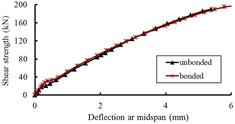
Effect of the bonding condition of pre-stressing tendon on shear capacity of the beams.
It can be seen that the ultimate strength and stiffness of the bonded pre-stressed concrete beam is slightly higher than that of the unbonded pre-stressed concrete beam, but the two are very close. As such, it can be concluded that the bonding conditions of the pre-stressing CFRP tendons have no significant effect on the shear capacity of the pre-stressed concrete beam. Moreover, the stress increment on pre-stressing CFRP tendons is not significant under different bonding conditions.
Conclusion
A total of 23 concrete beams were tested to investigate the shear behavior of concrete beams pre-stressed with CFRP tendons. Numerical analysis using the FE software ANSYS was also carried out. The major findings from the results of the experimental and numerical analyses are as follows:
The concrete beams pre-stressed with CFRP tendons have two typical shear failure modes based on different shear span–depth ratios: inclined compression failure and shear compression failure, regardless of whether pre-stressed concrete beams have steel stirrups or not.
The shear span–depth ratio a/d is the most important factor determining the failure mode of the concrete beams pre-stressed with CFRP tendons. For pre-stressed concrete beams without steel stirrups, when a/d ≤ 1, the beam fails at inclined compression of concrete; when a/d ≥ 2.5, flexural failure occurs; when 1 < a/d < 2.5, shear compression failure is observed. For pre-stressed concrete beams with steel stirrups, when a/d ≤ 1.3, inclined compression occurs in the beam; when a/d ≥ 2.6, the beam experiences flexural failure; when 1.3 < a/d < 2.6, shear compression failure is observed.
The shear span–depth ratio and stirrup ratio are the two important factors that affect the shear strength of the CFRP pre-stressed concrete beams. With the increase in the shear span–depth ratio, the shear strength of the concrete beams decreases gradually. The shear capacity of the concrete beams increases gradually with the increase in the steel stirrup ratio.
Based on the FE model, where the concrete beams pre-stressed with CFRP tendons mainly fail in shear compression, the effects of different factors on their shear strength were studied. The normal shear capacity of pre-stressed beams linearly increases with the increasing tensile strength of concrete. The shear capacity of the pre-stressed beams increases slightly with the increase in the stirrup ratio when the shear span–depth ratio is equal to 1.29 or 1.94. The shear strength of the pre-stressed beams increases with the increase in the pre-stressing level of the CFRP tendons, and the rate of increase changes with different pre-stressing forces. The bonding conditions of the pre-stressing CFRP tendons have no significant effect on the shear capacity of the pre-stressed concrete beam.
Footnotes
Acknowledgements
The authors are grateful to other participants of the projects for their cooperation.
Handling Editor: Ismet Baran
Declaration of conflicting interests
The author(s) declared no potential conflicts of interest with respect to the research, authorship, and/or publication of this article.
Funding
The author(s) disclosed receipt of the following financial support for the research, authorship, and/or publication of this article: This research was jointly funded by the National Key Research and Development Program of China (grant no. 2016YFC0701100), the National Natural Science Foundation of China (grant nos 51308028, 51408026, 51378046, and 51608238), the Science and Technology Fund of Beijing Education Committee (grant no. KM201610016012), Beijing Municipal Natural Science Foundation (grant no. 8162015), and the Fundamental Research Funds for Beijing Universities (grant no. X18146).