
Abstract
In order to obtain a larger damping force with the limited axial size of the vehicle suspension system, a new magnetorheological damper with serial-type flow channels was developed. The piston head was equipped with two piston end covers, three piston non-magnetic sleeves, and four piston magnetic sleeves, which were sequentially combined into three serial-type flow channels to form three groups of effective damping gaps. The structure and principle of the proposed magnetorheological damper were described in detail, and the model for calculating damping force was deduced too. Simulation and analysis for the proposed magnetorheological damper was implemented using electromagnetic field simulation software. The damping performance was tested and analyzed on the test rig under different applied current, amplitude, and frequency excitation. The experimental results show that the damping force is 6838 N under the load excitation with frequency of 1 Hz, amplitude of 7.5 mm, and current of 1.5 A, which is 1.6 times than the expected damping force. The equivalent damping coefficient is attained to 290 kN/s m−1, which shows that the developed magnetorheological damper has high vibration control ability and good mechanical properties.
Keywords
Introduction
Vehicle suspension is the key component for improving the vehicle operation stability and ride comfort. Its mitigating vibration performances are particularly important.1,2 The traditional passive suspension, active suspension, and semi-active suspension have been applied to vehicles for vibration absorption.3,4 Among of them, the traditional passive suspension could not adjust its dynamic characteristic in real time according to the external disturbance. 5 The active suspension has the perfect control effect, but its cost is higher, and it takes a lot of energy to guarantee it work normally. 6 Compared with these two suspensions, the semi-active suspension can adjust its dynamic characteristic without energy supply. 7 Therefore, many researchers at home and abroad have focused on the semi-active suspension.
With the emergence of new intelligent magnetorheological (MR) fluid, MR damper has been developed and applied to suspension system for semi-active control. Due to its excellent dynamic properties, such as the simple structure, larger damping force, wider adjustable range, fast response, and low power consumption, it is also widely used in bridge construction, military aerospace, and other industrial fields.8,9
To achieve a larger damping force, many different types of studies have been reported. A three-coil MR damper was developed by Lord Corporation, which can increase the damping force by increasing the effective damping length with maximum 20t load.10,11 A double-coil MR damper with two winding grooves distributed in the axial of the piston head was presented, and the experimental results show that the output damping force is larger than that of conventional single-coil MR damper when the input current is in different directions. 12 Robinson developed a MR damper employing a valve filled with porous media. This design can increase the active length of the flow channel. When the magnetic field is applied in the axial direction by a solenoid wrapped around the valve, the damper can produce a larger damping force. 13 Mao proposed a flow mode bifold MR damper, and the MR valves are installed at each end of the damper. This developed MR damper can increase the damping force with the increasing of the flow channel for the MR valve. 14 Bai et al. designed a MR damper utilizing an inner bypass valve for ground vehicle suspension. In this design, the five electromagnetic coils are used for increasing the damping length which consists of six damping gaps, and the annular flow gap made up of the bobbin and outer tube is an inner bypass annular valve. This MR damper can generate large dynamic range and damping force. 15 Liao et al. designed a MR damper equipped with an external MR valve with multi-stage radial flows. The experimental results show that it can increase the damping length and obtain the large damping force. 16 Zhu et al. developed a MR damper with both annular and radial channels in the piston head. It can output the damping force of 3500 N and presents good damping performance. 17 Yazid et al. designed a shear and squeeze MR damper, which is set up with five groups of excitation coils. The developed MR damper can increase the effective axial and radial damping lengths. So the large damping force is also obtained. 18 Kim et al. proposed a novel MR damper featured with bifold flow mode and equipped with the outer piston and inner piston, which can increase the number of the damping channel. The proposed MR damper can achieve a lager damping force. 19
In order to obtain the lager damping force of the MR damper for vehicle suspension system, the traditional methods are to increase the damping length by increasing the length of the piston, the number of the excitation coil or adding the external devices such as MR valve. However, these ways all enlarge the axial size and installation space of the MR damper, as well as shorten the damper stroke, which make the suspension system more complex. Hence, the MR dampers developed using the above methods are not suitable for the vehicle suspension system.
In the view of the above-mentioned facts, a new MR damper with serial-type flow channels is designed and developed. The presented MR damper relies on the increase of the radial dimension to increase the effective damping length and obtain a larger damping force. The mathematical model is derived and the magnetic circuit is calculated. Then, the proposed MR damper is manufactured. Finally, the simulation analysis and experimental tests are carried out.
Design of the MR damper with serial-type flow channels
Working principle and structure design
Figure 1 shows the working principle of the traditional single-coil MR damper. It mainly consists of piston head, piston rod, floating piston, cylinder, end covers, and excitation coil. During the movement of the piston rod, the annular gap is formed between the piston head and the cylinder. When the direct current is applied to the excitation coil, a magnetic field occurs around the piston head. That is, the effective resistance lengths of ta and tb play an important role in producing the controllable damping force.

The traditional MR damper.
However, the resistance length of the piston rod cannot be enlarged as far as possible due to the size limitation in the axial directions. So another way to lengthen the effective resistance gap is put forwarded in the radial directions.
Figure 2 shows the structure of the developed MR damper with serial-type flow channels. The piston of the developed MR damper is mainly composed of the piston upper and lower coves, magnetic sleeves I, II, III, and IV, outer sleeve, and non-magnetic sleeves I and II, respectively. Observing Figures 2 and 3, the magnetic sleeves I and III, non-magnetic sleeve I, and the piston constitute the inner channel and the inner gaps; magnetic sleeves II and III, non-magnetic sleeve II, the magnetic sleeves I and III, and non-magnetic sleeve I constitute the middle channel and middle gaps; magnetic sleeves II and III, non-magnetic sleeve II, and outer sleeve constitute the outer channel and the outer gaps. The inner channel, middle channel, and outer channel are sequentially combined into serial-type flow channels. When the piston head moves under the external excitation, the MR fluid flows from the input, then along the inner channel, middle channel, and outer channel to the output.

Schematic diagram of MR damper with serial-type flow channels.
Fluid flow paths of the developed MR damper.
As shown in Figure 3, the inner gaps, the middle gaps, and the outer gaps were sequentially combined into three groups of effective damping gaps. When the excitation coil is loaded with current, MR fluids in the inner, middle, and outer gaps change from the liquid state into solid state rapidly in the presence of the magnetic field generated by excitation coil. As a result, the pressure differential is obtained at both ends of piston to resist the external vibration. Furthermore, with the increase of the current, the pressure differential increases constantly before the saturation of magnetic flux density in the magnetic circuit. Therefore, the damping force generated by the developed MR damper can be controlled by the current.
Figure 3 also shows the distribution of magnetic flux lines generated by the excitation coil. When the excitation coil is applied with the current, the magnetic flux lines begin with magnetic core of the piston, after which they go through the left side of piston, the left side of the inner gaps, the magnetic sleeve I, the left of the middle gaps, the magnetic sleeve II, the left side of the outer gaps, along the outer sleeve, through the right side of the outer gaps, the magnetic sleeve III, the right side of the middle gaps, the magnetic sleeve IV, the right side of the inner gaps, and then return to the magnetic core of piston head to achieve the closed magnetic circuit.
Figure 4 shows the structure diagram of the magnetic sleeve I or III, in which the bye hole is set. The inner channel, middle channel, and outer channel are connected serially by the bye hole of the magnetic sleeve I or III.
The magnetic sleeve I or III.
Magnetic circuit of the developed MR damper
The simplified magnetic circuit of the developed MR damper is shown in Figure 5, and the key parameters are listed in Table 1. According to the magnetic Ohm’s law, the calculation model of the magnetic circuit can be described as 20
where N is the number of the turns for excitation coil, I is the excitation current, li is the length of the path that magnetic flux passes through the permeability magnetic material, Si and Sζ are the cross-sectional areas of the permeability magnetic material and the damping gaps through which the flux linkage passes, µi is the relative permeability of the permeability magnetic material, µ0 is the permeability of vacuum, and δζ is the width of the damping gaps.
The simplified magnetic circuit of the developed MR damper.
Key parameters of the developed MR damper.
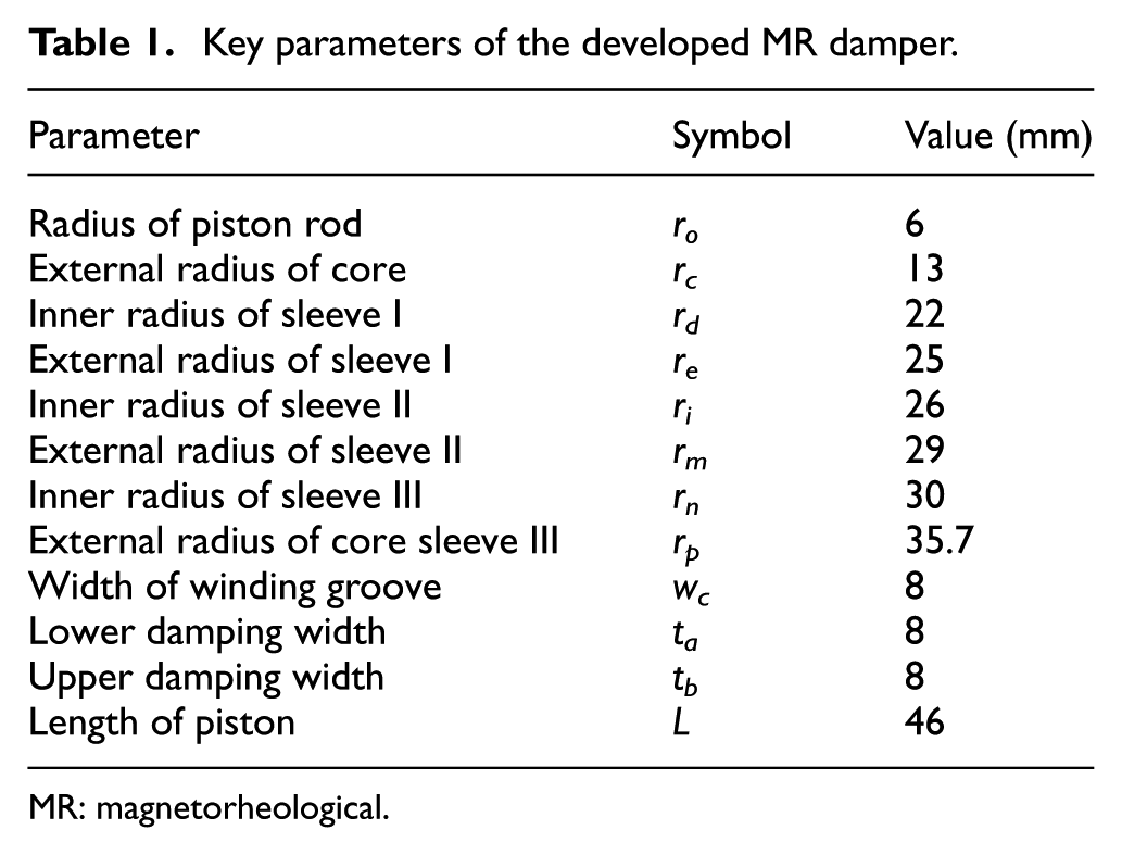
MR: magnetorheological.
Let Ri and Rζ represent the magnetic resistance of the ith and ζth path that magnetic flux passes through the permeability magnetic material and the damping gaps, respectively. The equation of the Ri and Rζ can be expressed as

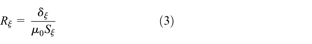
Hence, the magnetic resistance of the overall paths can be expressed respectively as follows


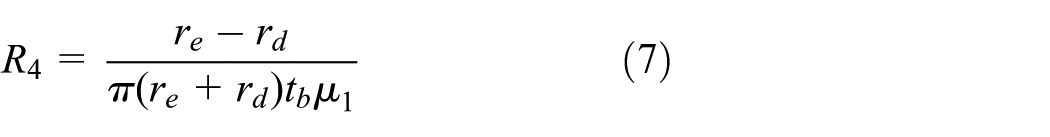


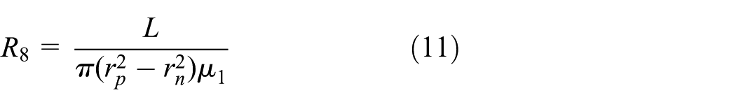
Because the piston head of the developed MR damper is the symmetrical structure, so the magnetic resistance of the rest paths of the magnetic flux can be replaced by the solved magnetic resistance. Therefore, the overall magnetic resistance Rm can be expressed as

According to the magnetic Ohm’s law, the magnetomotive force can be expressed as

where B0 is the magnetic flux density of the damping gaps and Sm is the magnetic flux area of the damping gaps.
Damping force calculation model
As shown in Figure 3, there is no relative motion between three damping sleeves and piston heads which contribute to the three flow channels. Hence, the working modes of the MR fluid in the inner, middle, and outer flow channels are the flow mode.
The damping force F of the single damping channel can be expressed as

where η is dynamic viscosity of MR fluid, τy is shear yield strength of MR fluid, v is the relative speed of the piston and cylinder, D′ is the average circumference of damping channel, h is the width of damping gap, l is the length of the effective damping, and Ap is the effective area of piston under normal operation which can be expressed as

where D is the diameter of the piston and d is the diameter of the piston rod.
Hence, the mathematical model of the damping force can also be expressed as

In equation (16), the first term represents the uncontrollable damping force Fη, and the second term represents the controllable damping force Fτ. So damping adjustable range λ can be expressed as

Modeling and simulation analysis
The MR fluid with type of MRF-J25T provided by the Chongqing Instrument Material Research Institute in China was used in the following simulations and experiments. Its characteristics are shown in Figure 6.

Characteristic curve of MRF-J25T: (a) ty-B curve and (b) H-B curve.
The Emag module of the finite element software ANSYS is adopted to simulate and analyze the static magnetic field of the developed MR dampers with serial-type flow channels. Figure 7 presents the finite element analysis model of the designed MR damper. In this model, the piston, piston permeability sleeves, and piston outer sleeve are made from high-permeability materials No.10 steel; the excitation coil is made up of varnished copper wire; damper end cover, piston upper and lower covers, and piston rod are made of non-magnetic materials, respectively.

Finite element analysis model of MR damper: (a) entity model and (b) meshing model.
Figure 7(b) shows the finite element meshing model of MR damper, there are 829 elements, and 2572 nodes in the meshing model. After meshing process, the load and boundary conditions were set up. In this process, the parallel magnetic force lines condition was loaded on the meshing model as boundary condition.
Figure 8 shows the magnetic flux lines and the magnetic flux density of the developed MR damper, respectively, with the excitation current of 1 A. As shown in Figure 8(a), the magnetic flux lines are perpendicular to the effective damping gaps, which are shown as the closed-loop circuit. Observing Figure 8(b), when the exciting coil is loaded with the current of 1 A, the magnetic flux densities of three flow channels from inner path to the outer path can reach to 0.35, 0.28, and 0.22 T, respectively, which show a gradual decrease trend. Furthermore, there is no leakage of magnetism.

Results of finite element analysis: (a) magnetic flux lines and (b) magnetic flux density.
Figure 9 shows the average magnetic flux density in the intermediate path of three fluid flow channels. When the excitation coil is loaded with the same current, the magnetic flux area increases with the radius increasing, which leads to a reduction of magnetic flux density of three flow channels along piston radial from inner channel to outer. When the exciting coil is applied with the current of 1.75 A, the magnetic flux density in the inner channel reaches to 0.5 T, which is just needed for reaching the saturation point of the MR fluid. In addition, the average magnetic flux density of middle channel is about a half of the sum of the magnetic flux density of inner and outer channels.

Magnetic flux density of three channels.
Figure 10 shows the damping force of three fluid flow channels and the total force with different exciting current, respectively. When the zero current is input to exciting coil, the damping force of the three channels presents mainly the viscous damping force, and the total viscous damping force is greater than 300 N, which reaches to the target of viscous damping force for the damper. However, with applied current increasing, the output damping force is mainly expressed as the coulomb damping force. When applied current reaches to 1.5 A, the maximum damping force is 2.7 times than the expected damping force.

Damping force of different flow channels.
To evaluate the dynamic characteristics of the proposed MR damper, the dynamic performance is obtained by Simulink tool under the sine excitation with the interval of 0.001 s, as shown in Figure 11.
Dynamic characteristics of MR damper: (a) damping force and displacement and (b) damping force and velocity.
Figure 11(a) shows the output damping force pertaining to the displacement, which appears to the shape of “back to the font.” The output damping force increases with the applied current increasing, and the area of the back to the font also becomes larger. In addition, when the applied current is close to 1 A, the growing range of damping force decreases gradually, which indicates that the MR fluid in the three damping channels tends to saturation point with the influence of magnetic field. As shown in Figure 11(b), the output damping force increases with the piston velocity of the developed MR damper increasing. Under the same excitation current and velocity, the damping force presents symmetry with respect to zero velocity in the positive and negative directions.
Experimental analysis and discussions
Prototype and test system setup
Figure 12 shows the key parts and prototype of the MR damper with serial-type flow channels. Figure 13 shows the dynamic performance test system, which mainly consists of the power supply, the proposed MR damper, the Instron fatigue test machine, and the computer controller. The Instron fatigue test machine with model 8872 can produce force capacity up to ±25 kN, its load weighing accuracy can reach to ±0.5%, the hydraulic pressure requires 20.7 MPa, and it can work in operation environment with temperature from +10°C to+38°C with 10%–90% humidity non-condensing. The power applies the WYK-303B2, it can output 0–30 V, its voltage regulation can be lower than 5 × 10⁻³, and its ripple voltage is lower than 2 mV. When the damper is fixed with fatigue test machine through hydraulic clamp, the excitation coil is connected to an external power supply and the fatigue test machine is set with excitation frequency and amplitude; the damping force of the developed MR damper can be monitored by computer controller in real time.
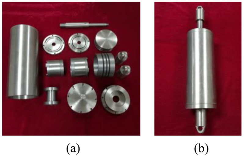
MR damper with serial-type flow channels: (a) key parts and (b) prototype.

Performance test system of MR damper.
Damping performance under zero excitation current
Figure 14 shows the damping performances of the developed MR damper under the zero excitation current. In the test, the testing frequency is set as 0.5 Hz and the amplitude of the test machine is selected as 2.5, 5, 7.5, and 10 mm, respectively. As shown in Figure 14(a), the output damping force increases with the increase of the excitation amplitude. At the same time, it is obvious that the excitation amplitude changes equivalently and the damping force also changes equivalently. In addition, when the amplitude of the test machine is 10 mm, the damping force can reach to 1500 N, which can guarantee the normal use of the suspension system mounted with the developed MR damper.

Damping force under zero excitation current: (a) damping force and displacement and (b) damping force and velocity.
Figure 14(b) shows the relationship between damping force and the damper velocity. Due to the zero excitation current, the output damping force is only the uncontrollable damping force, which is related to the main structural dimensions and damper velocity of the proposed MR damper. In addition, the damping force is approximately linear with the damper velocity. At the same time, while the excitation frequency remains constant, the damper velocity increases with the increase of amplitude, which causes the increase of the damping force.
Damping performance under different amplitudes
Figure 15 shows the damping performances of the developed MR damper under the different damper amplitudes. In the test, the direct current of the excitation coil is fixed as 0.75 A, and the testing frequency is set as 0.5 Hz. Here, the amplitude of the test machine is selected as 2.5, 5, 7.5, and 10 mm, respectively. As shown in Figure 15(a), the damper velocity increases with the increase of amplitude; this makes the uncontrollable damping force increase and brings about an increase of the maximum damping force. As shown in Figure 15(a) and (b), it can be seen clearly that the variation of amplitude for the maximum damping force decreases with the increase of the amplitude, which indicates that the controllable damping force influenced by the current plays an important role on the total damping force. Furthermore, due to the existence of current, the damping force does not remain linear with the damper velocity.

Damping force under different amplitudes: (a) damping force and displacement and (b) damping force and velocity.
Damping performance under frequency
Figures 16–18 show the damping performance under different frequencies at the amplitudes of 2.5, 5, and 7.5 mm, respectively. In the test, the direct current of the excitation coil is also fixed as 0.75 A, and the testing frequency is set as 0.25, 0.5, 0.75, and 1 Hz, respectively. It is apparent that the damping force increases with the increase of the amplitude or the frequency under the same current. Nevertheless, the variation of the amplitude and frequency has a small impact on the damping force. In addition, the characteristics of controllable damping force influenced by the current do not change. When the current is applied as 0.75 A, the maximum positive damping force reaches to 5814 N, and the maximum negative damping force reaches to 6600 N. The range of the damping force is 11.8.

Damping force under different frequencies at the amplitude of 2.5 mm: (a) damping force and displacement and (b) damping force and velocity.

Damping force under different frequencies at the amplitude of 5 mm: (a) damping force and displacement and (b) damping force and velocity.

Damping force under different frequencies at the amplitude of 7.5 mm: (a) damping force and displacement and (b) damping force and velocity.
As it can be seen from Figures 16(a), 17(a), and 18(a), the curves showing the relationship between damping force and displacement are not saturated. The reason is that the proposed MR damper cannot provide the adequate compensatory pressure in time due to the movement of the floating piston.
Damping performance under different input current
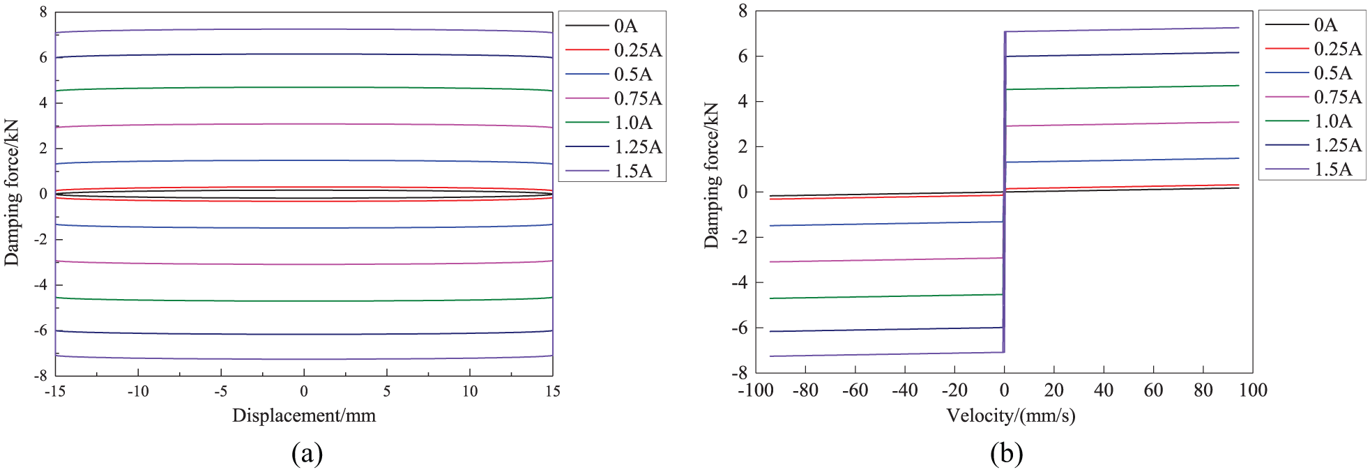
Figure 19 shows the damping performances of the developed MR damper under the different input current. In the test, the amplitude of the test machine is 5 mm and the testing frequency is 0.5 Hz. Here, the applied current is 0.25, 0.5, 0.75, 1.0, 1.25, and 1.5 A, respectively. It is clearly known that the damping force increases with the increase of the current. When the excitation current does not exceed 1.0 A, the current plays a significant role on the damping force. In addition, when the current exceeds 1.0 A, the magnetic flux density of MR fluid reaches to the saturation point of the magnetic circuit, and the damping force changes slightly.

Damping force under different current.
As shown in Figure 19, when the excitation current is 1.5 A, the maximum positive damping force reaches to 5486 N, and the maximum negative damping force reaches to 6838 N. The range of the damping force is 12.3. Besides, due to the self-weight of the piton head and rod, the maximum damping force in the negative direction is slightly greater than the maximum damping force in the positive direction.
As shown in Figure 20, the experimental damping force is compared with the simulated results to confirm the feasibility of the established damping force model. Due to the friction between three O-rings mounted on the surface of the piston outer sleeve and the cylinder inner, the experimental damping force slightly exceeds the simulated damping force. Nevertheless, the growth trend of the damping force simulated by the analytical model agrees well with that of the experimental damping force.

Damping force comparison between experimental tests and simulated results.
Figure 21 shows the variation of the damping adjustable range under the different applied current. In the test, the amplitude of the test machine is 5 mm and the testing frequency is 0.5 Hz. As the current increasing from 0.25 to 1.0 A, the damping adjustable range is approximately proportional to the increase of the current. When the current is 1.5 A, the damping adjustable range of the developed MR damper reaches to 7, which exhibits good dynamic regulation performance. Furthermore, when the current exceeds 1 A, the magnetic circuit of the developed MR damper reaches to the saturation point. Thus, the damping adjustable range changes slowly.

Damping range under different applied current.
Figure 22 shows the equivalent damping coefficient under the different applied current. It is obvious that the equivalent coefficient increases with the increase of the applied current. Observing Figure 22, the equivalent coefficient for current of 1.0 and 1.5 A is 290 and 300 kN s/m, respectively. It demonstrates that the developed MR damper has higher control vibration ability. Besides, when the current exceeds 1.0 A, the equivalent damping coefficient saturates.

Equivalent damping coefficient under different applied current.
Conclusion
This article presents a novel MR damper with serial-type flow channels to obtain the large damping force. Based on the limitation of the axial size, the developed MR damper was designed and manufactured by increasing the radial size to increase the effective damping length.
The electromagnetic field analysis of the developed damper was achieved using ANSYS software, and the simulated maximum damping force achieves 6517 N at the applied current of 1.5 A. Under the excitation with different applied current, different frequency and displacement amplitude, the dynamic performance of the MR damper was tested and analyzed on the test rig. The experimental results show that when the current is 1.5 A, the maximum damping force reaches to 6838 N. Furthermore, the dynamic adjustable range reaches to 7 and has good mechanical properties. The equivalent damping coefficient of the damper comes up to 300 kN s/m, indicating that the developed MR damper has higher control vibration ability.
Footnotes
Handling Editor: Ali Kazemy
Declaration of conflicting interests
The author(s) declared no potential conflicts of interest with respect to the research, authorship, and/or publication of this article.
Funding
The author(s) disclosed receipt of the following financial support for the research, authorship, and/or publication of this article: This research was financially supported by the National Natural Science Foundation of China (nos 51765016, 51475165, 11462004), the Jiangxi Provincial Foundation for Leaders of Academic and Disciplines in Science (no. 20162BCB22019), and 5511 Science and Technology Innovation Talent Project of Jiangxi Province (no. 20165BCB18011).