
Abstract
Considering rub-impact forces, eccentricity of rotor, and nonlinear stiffness of armature shaft, a dynamic differential equation is built to investigate the bifurcation and chaos behavior of the locomotive traction system. The nonlinear analysis methods are inclusive of bifurcation diagrams, phase plane portraits, Poincaré maps, displacement–time curves, and spectrograms. The simulation results reveal the complex dynamic comprising period-3 to quasi-periodic bifurcation and intermittent bifurcation. Some research results are references for dynamic design and rub-impact fault diagnosis of the locomotive traction system.
Introduction
To improve output power of the traction motor, the gaps including the tip and bearing clearances between the rotor and stator of motor are usually designed as small as possible. With the increase in the machinery operating speed and the decrease in the rotor–stator clearance, the rub-impact fault between rotatory and stationary components becomes one of the main serious malfunctions that often occur in rotating machinery, in which chaotic vibration can be found under some circumstances. 1 The nonlinear dynamic problems caused by rub-impact fault have become the most interesting research areas, which are widely researched by the academy and engineering with the development of nonlinear dynamics theory. 2
In the past decades, there have been lots of literatures that focus on the motor rotor system. Chu and Lu 3 performed an experiment to study the fault phenomena in a rubbing rotor system. It was found that the system showed nonlinear characteristics such as quasi-periodic and chaotic motion. According to the stability and bifurcation theory, Zhang and Meng 4 analyzed the stability range of rotor rub-impact system by establishing the model of micro-rotor system. Luo et al. 5 proposed a mathematical model for a rotor–bearing system with coupling fault of crack and rub-impact. Meantime, the nonlinear behavior of rotor loose and rub-impact coupling fault was simulated, and the complex dynamical features such as single period, double period and chaos were also found. Yao et al. 6 researched dynamic characteristics of a rub-impact rotor based on the theory of harmonic balance. It was proven that the ratio of higher order harmonic components of any two nodes of rub rotor system was equal to that of correlation elements of frequency response matrix in a non-fault rotor system. Wang et al. 7 established a dynamic model of rotor–bearing systems considering rub-impact force and oil film force, and researched the nonlinear dynamic phenomena and stability of periodic response of the system. To illustrate the effect of the important parameters on the system response, Chang-Jian and Chen 8 investigated the nonlinear problem of a rub-impact rotor supported by turbulent couple stress fluid film journal bearings. Some types of response diagrams including bifurcation diagrams, phase plane portraits, and Poincaré maps were also identified by employing suitable methodologies.
The investigation on nonlinear vibrations of rub-impact faults are usually based on Jeffcott rotor,9,10 turbo-generator,11,12 water-turbine generator set, 13 aero-engine rotor, 14 and so on. Aiming at the coupling fault of axial load and radial rub, a geometric nonlinear rotor–casing system was developed by Yang et al. 15 Meanwhile, a dual-disk rotor system capable of describing the mechanical vibration resulting from multi-unbalances and multi-fixed-point rub-impact faults was formulated using Euler beam element. 1 Wang et al. 16 established a dual-rotor system capable of describing the mechanical vibration caused by rubbing fault, in which the compressor disk and turbine disk were considered in both inner rotor and outer rotor. To reveal the influence of random stiffness on the nonlinear response of rub-impact rotor, Yang et al. 17 studied the bifurcation and chaos behavior of a rub-impact rotor system with random stiffness by Taylor series expansion and Chebyshev polynomial approximation method. Cveticanin 18 discussed the effect of material nonlinearity in the forced vibrations of rotors and then developed an averaging method for obtaining the amplitude and phase variation in time. In Ma et al., 19 the fault characteristics of a single span rotor system with two disks were investigated when the rubbing between a disk and an elastic rod (a fixed limiter) occurred.
From the references mentioned above, literature reviews indicate that different methods have been adopted to analyze the dynamics characteristics of rub-impact rotor system; however, very limited works have addressed the effect on the dynamic response of traction motor for railway locomotive. Due to increasing demands to improve the speeds and load-carrying capacities of trains, locomotives with high power levels are urgently needed, which will create new challenges for locomotive traction motor. Once the eccentricity of the rotor is larger, or the bearing fault occurs, it may cause the collisions and friction between rotor and stator of traction motor. In Tang et al., 20 the rub-impact fault of traction motor was also called sweep bore of traction motor. Rotor-to-stator rub is a serious malfunction in transmission system of the locomotive, and it often causes catastrophic failure and subsequent economic loss. Therefore, dynamic problem caused by rub-impact fault must be considered for structure design, vibration control, and fault diagnosis of the locomotive traction system. At present, it is usually assumed that the material of armature shaft is a single material; hence, in most of the papers, the forced vibrations of the linear rotor are considered. However, the shaft material of traction motor for locomotive is usually made of composite materials, the forced vibrations of the nonlinear rotor can often be obtained.
This article aims to study the new methodology of nonlinear dynamic problem caused by rub-impact and nonlinear stiffness of armature shaft of traction system for locomotive. Considering the factors such as rub-impact forces, eccentricity of rotor, and nonlinear stiffness of armature shaft, a common model of traction system is developed. The complex nonlinear dynamic phenomena of the locomotive traction motor are discussed along with the changes of the rotating speed of the traction motor and damping of rotor at the disk. It is expected that valuable dynamic features of locomotive traction system can be observed, so as to provide references for the evaluation of the traction system condition and early prediction of the rub-impact.
Physical model and governing equations
The traction transmission system of locomotive is mainly composed of traction motor, gear pair, and wheel set. As illustrated in Figure 1, the motor rotor, armature shaft, and rolling bearing can be regarded as simply supported beam structure. Supposing the rotor-to-stator rub is the partial rubbing, and it can be described by Coulomb equation, then the rub-impact model of traction system can be simplified as shown in Figure 2.

Schematic of the traction transmission system of locomotive: (a) traction transmission system and (b) locomotive traction motor.

Mechanical model of rub-impact traction rotor: (a) schematic of rubbing rotor and (b) schematic of rub and impact forces.
Rub-impact force of traction motor
It is assumed that there is an initial clearance of δ between the rotor and stator, and the rotational speed of rotor is

where
Let

Dynamic equations of the traction motor system
Most of the work done in the rotor’s vibrations has been for material with linear stress–strain laws. 18 When the high temperature and creep behavior of the material occurs, the stress-strain laws are nonlinear. From the experimental tests, the stress–strain relation is given as 18

Then, the elastic forces of rotating shaft are defined as follows

where k and k1 are the linear and nonlinear stiffness values of rotating shaft materials, respectively. It is assumed that x and y are radial and axial displacements in the disk position, respectively. Taking into account the rubbing forces, eccentric forces, and gravity, the equation for the system can be written as follows

where m is the mass of the disk, c is the damping coefficient of rotor at the disk, k indicates the stiffness coefficient, e represents unbalance, and g is the acceleration of gravity. To give the equations a dimensionless form, it can be initially assumed as below

Hence, the dimensionless forms of 2-degrees-of-freedom model of traction system can be simplified as 21

Simulation analysis of nonlinear dynamic characteristic
Based on the non-dimensional model above, computer numerical simulation is carried out by Runge–Kutta method, and the basic parameters of the simulation are chosen as follows: m = 300 kg,
Effect of rotating speed of traction motor
The bifurcation diagram is a useful tool for observing dynamic responses. Figure 3 illustrates the bifurcation diagram of traction system in dimensionless displacement X with the speed of traction motor changes, where the critical speed of motor is 1550 r/min. The system responses have many motion forms including multi-periodic, quasi-periodic bifurcation, intermittent bifurcation, and chaos. Moreover, when the dimensionless displacement satisfies conditions, X > 1 or Y > 1, the radial displacement r > 1, then the radial displacement is bigger than the gap between the rotor and stator, that is, r > δ, and it means that rub-impact occurs. Obviously, when the speed is changed at district of 2250 ∼ 2650 or 4750 ∼ 5000 r/min, r > 1, and the rub-impact fault happens. To describe the dynamic behavior and evolution process, the phase plane diagrams, Poincaré maps, time-domain response diagrams, and amplitude–frequency spectrums are adopted as shown in Figures 4–9.

Bifurcation diagram using rotating speed ω as control parameter: (a) global bifurcation diagram and (b) local bifurcation diagram.

Dynamic characteristic curve of the system at ω = 1200 r/min: (a) phase plane diagram, (b) Poincaré map, (c) time-domain response diagram, and (d) amplitude–frequency spectrum.
Dynamic characteristic curve of the system at ω = 1600 r/min: (a) phase plane diagram, (b) Poincaré map, (c) time-domain response diagram, and (d) amplitude–frequency spectrum.

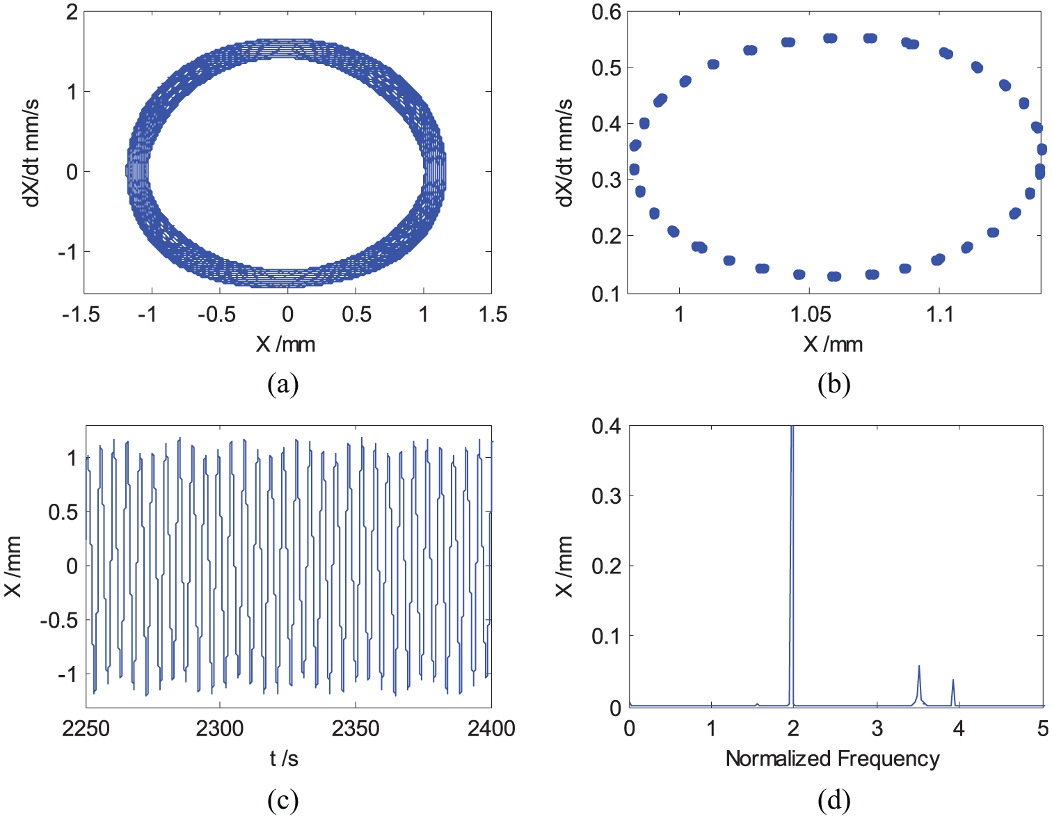
Dynamic characteristic curve of the system at ω = 2340 r/min: (a) phase plane diagram, (b) Poincaré map, (c) time-domain response diagram, and (d) amplitude–frequency spectrum.

Dynamic characteristic curve of the system at ω = 2600 r/min: (a) phase plane diagram, (b) Poincaré map, (c) time-domain response diagram, and (d) amplitude–frequency spectrum.

Dynamic characteristic curve of the system at ω = 3000 r/min: (a) phase plane diagram, (b) Poincaré map, (c) time-domain response diagram, and (d) amplitude–frequency spectrum.

Dynamic characteristic curve of the system at ω = 5000 r/min: (a) phase plane diagram, (b) Poincaré map, (c) time-domain response diagram, and (d) amplitude–frequency spectrum.
When the speed of the traction motor is less than 1600 r/min, that is, at 1200 r/min, the phase diagram has one closed circle, as can be seen in Figure 4, Poincaré map shows a fixed point, time-domain waveform is sine curves for the rules, and amplitude–frequency spectrum also has one peak amplitude, where 1 times frequency represents 50 Hz. It is obviously that the system is in period-1 motion. 19 When the speed exceeds critical speed, vibration is increased. When speed is equal to 1600 r/min, the phase plane graph traverses ring at any point, and Poincaré map is almost closed curve, as displayed in Figure 5. These results prove that the quasi-periodic motion appears in the traction transmission system, 7 and it keeps the state for a long range until 2330 r/min. When the speed is equal to 2340 r/min, the response of the system is in so-called “period-3” motion according to the phase plane graph shown in Figure 6, and three fixed points shown in Poincaré map.
When the speed exceeds 2340 r/min, the system leaves period-3 motion rapidly and comes into quasi-periodic bifurcation again, and it remains in the state from 2350 to 2650 r/min, as shown in Figure 7. In the simulation analysis mentioned above, the rub-impact fault happens at district of 2250 ∼ 2650 r/min. If the speed is increased from 2660 to 2850 r/min, the quasi-periodic motion is replaced by period-1 motion. When
As shown in Figure 3, when the speed continues to increase, the system enters into inverted bifurcation from period-2 motion to period-1 motion at district of 3110 ∼ 4750 r/min. With the speed near 4760 r/min, however, intermittent bifurcation and chaotic vibration emerge, the rub-impact fault occurs, and it keeps the state until 5000 r/min. As illustrated in Figure 9, phase plane portraits infinitely loop in the enclosed area, but never duplicates, the return points in Poincaré map form a geometrically fractal structure, time-domain response shows a non-periodic, and amplitude–frequency spectrum is continuous. All of these phenomena indicate that the system response is chaotic motion. Once the speed exceeds 5000 r/min, the period-1 motion can be observed by Figure 3.
Effect of the damping ratio
For convenience, taking the damping ratio as control parameter, the bifurcation diagrams of the system are obtained when the damping ratio ξ is changed from 0.03 to 0.20. As shown in Figure 10, the response of the traction rotor system undergoes a process from quasi-periodic motion through period-2 motion to period-1 motion with the rotating speed equals 1000 r/min.

Bifurcation diagram using damping ratio ξ as control parameter: (a) global bifurcation diagram and (b) local bifurcation diagram.
When ξ is less than 0.076, the phase plane portraits become regular, and the attractors of the Poincaré maps have a closed curve. It is evident from Figure 11 that the system is in quasi-periodic motion. When ξ reaches 0.076, quasi-periodic motion is replaced by period-2 motion. When ξ is higher than 0.082, the system leaves period-2 motion and finally returns into period-1 motion as shown in Figures 12 and 13. It is indicated that increasing damping can effectively suppress quasi-periodic and multi-periodic vibration.

Dynamic characteristic curve of the system at ξ = 0.07: (a) phase plane diagram, (b) Poincaré map, (c) time-domain response diagram, and (d) amplitude–frequency spectrum.

Dynamic characteristic curve of the system at ξ = 0.076: (a) phase plane diagram, (b) Poincaré map, (c) time-domain response diagram, and (d) amplitude–frequency spectrum.

Dynamic characteristic curve of the system at ξ = 0.082: (a) phase plane diagram, (b) Poincaré map, (c) time-domain response diagram, and (d) amplitude–frequency spectrum.
Conclusion
This article aims to reveal the influence of nonlinear stiffness model under specific excitation on the nonlinear response of rub-impact rotor system. These results are useful for the design and vibration control of the locomotive traction system. Based on the results of above study, some conclusions can be summarized as follows:
With the increase in the speed of traction motor, vibration of the system increases, especially at district of 2250 ∼ 2850 r/min, the rotor-to-stator rub-impact fault of locomotive traction system happens. Hence, the rated speed of the traction motor can be chosen near 1500 r/min.
For the multi-periodic, quasi-periodic, and chaos motions, amplitude-spectrum diagrams contain 1 and 1.5 times harmonic components, which can be used as the basis for the existence and identification of rub-impact phenomenon, and the bigger the frequency doubling amplitude is, the more serious the rub-impact fault is.
Increasing damping of rotor at the disk can effectively suppress quasi-periodic as well as multi-periodic vibration and improve the stability of the traction system. In this study, the damping ratio can be chosen to be greater than 0.082.
Footnotes
Acknowledgements
The authors thank the anonymous reviewers for their valuable comments.
Handling Editor: Sunan Huang
Declaration of conflicting interests
The author(s) declared no potential conflicts of interest with respect to the research, authorship, and/or publication of this article.
Funding
The author(s) disclosed receipt of the following financial support for the research, authorship, and/or publication of this article: This work was supported by the National Natural Science Foundation of China (No. 51475386) and National Basic Research Project of China (973 Program, No. 2015CB654801).