
Abstract
The top drive for casing running system can effectively avoid borehole neck down and sticking, reducing construction period by about 50%. However, the casing will bear higher torque load, and the casing joint threads can meet the bearing performance, which have a critical impact on casing running and the life of oil and gas wells. Variable pitch can reduce thread stress concentration and improve load-bearing strength. Lacking research on mechanical behavior has greatly restricted the development of variable pitch thread. This article generated a variable pitch casing joint thread helix forming method and control equation; designed an ultrahigh-torque variable pitch casing joint thread based on the theory of screw transformation matrix; established a three-dimensional finite element model of the variable pitch casing joint; optimized the main structure parameters with the judgment of torque-bearing capacity; and conducted parameter-sensitivity evaluation of guide surface angle, bearing surface angle, pitch of box thread, and amount of varying pitch under tension load, compression load, bending load, and torque load. The designed variable pitch casing joint had been successfully used in several top driving casing running wells, downed to the maximum depth of 4375 m, the largest hole deviation angle of 55.37° and horizontal section length of about 260 m. Under a torque of 4000 N m, the top drive rotated down into the gas well successfully without failure. The research work of this article has significance on variable pitch thread and enhances the bearing capacity of the thread.
Introduction
The top drive for casing running system can significantly reduce formation collapse, borehole neck down and sticking, plus the ability to push down while rotating and circulation, helping to get strings to bottom, and reduce construction period by about 50%. 1 However, the existing casing joint lacks torsional resistance, which leads to casing failure, and the failure of oil and gas wells because of casing damage after casing running. Variable pitch structure is developed on the existing casing joint, which can reduce thread stress concentration effectively and improve load-bearing strength by means of load distribution homogenization. Lack of research on mechanical behavior has greatly restricted the development of variable pitch thread. Therefore, model establishment and mechanical behavior analysis have great significance on the development of a new generation of variable pitch joint threads.
Some scholars have done many studies on the mechanical behavior analysis of joint thread. Ushakov et al. 2 presented a method based on ultrasonic testing to detect the damage or defect of joint thread. Teodoriu and Badicioiu 3 used the improved “grooved-plate” method to test thread-compounds sealing capacity and contrasted experimental results to the theoretical analysis. Croccolo et al. 4 provided a useful experimental methodology to study the failure reason: the relation between friction coefficient and the torque of joint thread were analyzed by fatigue test. Korin and Ipiña 5 studied on crack initiation and fatigue crack growth of high-strength bolt thread. Full-scale test method6–8 is reliable to evaluate the performance of joint thread; however, due to the limitation of test conditions, the current experimental equipment cannot precisely or accurately understand the internal deformation law of joint threads.
With the appearance of finite element method, it has developed rapidly on the study of mechanical behavior of the joint threads. Some scholars established a two-dimensional (2D) finite element analysis (FEA) and studied on stress concentration coefficient on joint thread and stress distribution law under loads, analyzed the stress state and strain state under the make-up torque, evaluated the strength of thread, and studied the mechanical behavior of the pre-tightening torque under the analysis of the problem.9–12 Lopez-Arancibia et al. 13 presented that the mechanical evaluation method for the bending performance of the pre-tightening was bolted by preloading magnitude of interference. Calculation models mentioned above, based on 2D or three-dimensional (3D) simplified models cannot characterize the relationship of deformation coordination under torque load applied by preloading magnitude of interference on assembly.
Fukuoka et al.14–16 established a 3D model to analyze the mechanical behavior of casing joint under loads and provided a method for the design and analysis of conventional joint threads. However, variable pitch joint thread is a typical complex structure with irregular internal structure geometry and large span of structure size. There have been very few reports on structural mechanical behavior of the variable pitch joint thread.
This article generated a variable pitch casing joint (VPCJ) thread helix forming method and control equation; designed a ultrahigh-torque VPCJ based on the theory of screw transformation matrix; established a 3D whole structure finite element model (FEM) of VPCJ; optimized the main structure parameters with the judgment of torque-bearing capacity; and studied the VPCJ’s mechanical behavior under tension load, compression load, bending load, and torque load; and the sensitivity of the key structural parameters such as guide surface angle (GSA), bearing surface angle (BSA), pitch of box thread, and amount of varying pitch were evaluated.
Forming method and control equation of variable pitch helix
Forming method of variable pitch helix
In Figure 1, a point


Variable pitch helix line diagram.
The angular velocity
The angular velocity
The axial velocity
Mechanical analysis of variable pitch and thread under torque load
Figure 2 shows the mechanical characteristic of the joint threads under a torque load. 18

Mechanical characteristic of the joint threads with shoulder under a torque load.
A 2D model, which ignored the spiral angle of each independent tooth, cannot simulate torque load. Therefore, the 3D thread joint model considering spiral angle of each tooth is applied. Because the profile of the threaded teeth changes continuously along the spiral line, the 3D model can truly reflect the structural characteristics of the casing joint. The 3D thread joint model can also reflect the 3D stress characteristics under complex loading, especially under the torque load and the bending load.
A small section in the pin is taken out, and there have been the normal stresses

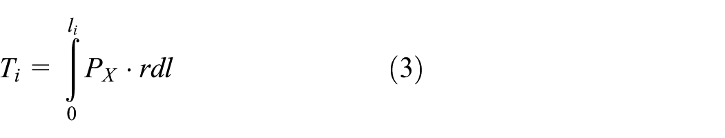
where r is the radius of engaged surface.
The force and the torque of all thread teeth are, respectively


Thus, torque can be converted into axial force and radial force. Under the force
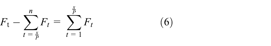
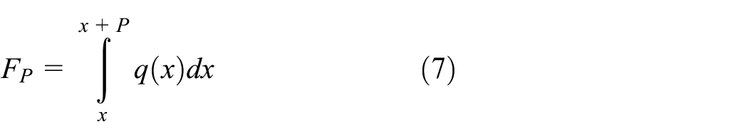
Let the load distribution intensity
The deformation of the internal threads body and the external threads body combined by engaged teeth are coordinated, and the deformation abovementioned are, respectively

To calculate the load distribution intensity
Control equation of variable pitch helix
In 3D spaces, any motion of variable pitch thread can be regarded as the thread section around an axis of rotation while moving along the axis. Figure 3 is the position vector spiral motion diagram. The position vector

where

Screw motion about
The previous screw transformation can be achieved by screw matrix, as follows 21
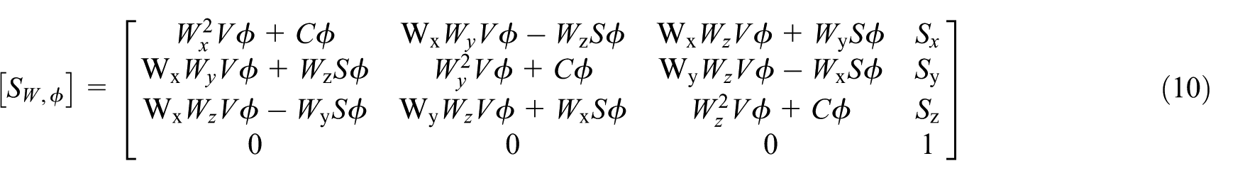
Where,

When the relation between

If the point p is on the axis

The corresponding position

When the relation between

where

Variable pitch helix.
Physical model of VPCJ
In this article, designed prototype is 7” buttress casing thread

Schematic diagram of VPCJ teeth.
3D full-size FEM of VPCJ
Numerical simulation model of ultrahigh-torque VPCJ
A 3D simulation model of VPCJ was established based on the virtual work principle and the large deformation theory. The VPCJ, made of 30Mn5 alloy with thermal refining, has the elastic modulus of
The C3D8R eight-node hexahedral linear reduction integral unit is used for the VPCJ meshing. The mesh of the VPCJ is refined as Figure 6, establishing a reference point at the center of the non-threaded end of the pin and making its kinematic coupling with the end face, imposing on the reference point clamped boundary to eliminate the degrees of freedom. Another reference point is established at the center of the non-threaded end of the box. Imposing on the reference point clamped boundary to eliminate the degrees of freedom, and the required load is applied.

Finite element mesh of the VPCJ teeth on pin and box.
Numerical simulation model validation
In order to ensure the accuracy of the calculation results, the numerical simulation model of threaded joint was established with the same experimental specifications proposed by Li et al. 23 The experimental conditions were studied as proposed by Li et al. 23 Under the experimental conditions, the stress changes at the outer edge of the box. The numerical simulation results and experimental results are shown in Figure 7.

Comparison of the finite element computation and experimental results.
From Figure 7, it can be seen that the two methods of stress results are generally the same, and the overall value difference is small. By comparison, the results of calculation and experiment are in good agreement, which confirms the accuracy of the 3D full-size FEM for the VPCJ.
Optimization of a high-torque VPCJ
The initial designed combination of thread parameter of ultrahigh-torque VPCJ cannot achieve the best result. For attaining an optimal parameter combination of the ultrahigh-torque VPCJ, based on the established calculation model, orthogonal optimization has been conducted on the key structural parameters of thread to obtain the optimal combination of parameters.
Orthogonal optimization factors
Table 1 shows the thread parameters levels of orthogonal optimization factors. Considering the thickness of casing wall, the taper of the box cannot be oversize. Its range was determined to be 1:9–1:13. For further illustration of the effect of pitch of box, BSA, GSA, amount of varying pitch, and the first teeth width of pin on the torque capacity of the VPCJ, the thread parameter values were defined uniformly at the right and left of the parameters of initial VPCJ during the correct engagement condition, so that the parameter values and calculation results are more representative.
Orthogonal optimization factor levels.

Analysis of orthogonal optimization test results
In order to obtain an optimizing performance of the VPCJ with torque load 40,590 lb ft, the stress results under 25 combinations of thread parameter combinations were calculated, and the results are shown in Table 2.
Orthogonal optimization results.

Under the torque of 40,590 lb ft, it can be seen from Table 2 that the stress results of different factors are different in extreme difference. The order of main and secondary effects of each factor on the torque performance is GSA, BSA, amount of varying pitch, the pitch of box, and the first teeth width of pin (B > A > D > C > E). Within the scope of study, the optimal combination of thread is: GSA (8°), BSA (11°), amount of varying pitch (0.48 mm), the taper of the box (1:13), and the first teeth width of pin (6.11 mm).
Mechanical behaviors analysis of VPCJ under loads
Based on the established VPCJ calculation model, the stress distribution and deformation coordination have been calculated under tension load, compression load, bending load, torque load, and have compared to that of the buttress casing thread, and the mechanical behavior of VPCJ has been studied.
Mechanical behavior of the VPCJ under torque load
Figure 8 shows the maximum Mises stress in each tooth in the pin of the VPCJ and buttress casing joint under different torque loads. Figure 9 shows Mises stress distribution cloud of joints under the torque load 40,590 lb ft.
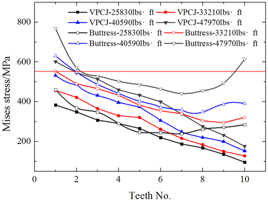
Mises stress of teeth under torque load.

Mises stress distribution cloud of teeth of pin under torque load 40,590 lb ft: (a) the VPCJ and (b) the buttress casing thread.
As Figure 8 shows, the stress values of the buttress casing thread presents as saddle shape, decreases at first and then increases slightly, but the stress values in each tooth of the VPCJ gradually decreases. The variable pitch structure changes the thread’s cross-sectional area to change stress state, the wider the thread’s cross-sectional area is, the higher the subject force and resistance to deformation are. Under the same torque load, the stress level of the VPCJ is much lower than that of the buttress casing thread. The first tooth of the buttress casing thread bears the largest stress. The stress values in each subsequent tooth have decreased gradually. The stress value of the last tooth has increased slightly. The variable pitch structure, increased thread’s cross-sectional area in the front of teeth, can improve bearing strength. The peak stress value in the first tooth is reduced, and its ability to resist deformation has been improved by means of lowering thread’s cross-sectional area in the final few teeth, which lowers the peak stress in the last few teeth and improves whole torque performance greatly. Under torque load 40,590 lb ft, the first tooth in the pin of the buttress casing thread has yield; and the first tooth in the pin of the VPCJ still has no yield, and the torque performance of the VPCJ is 22% higher than that of the buttress casing thread. Through the calculation of different torque loads, the ultimate torque load can be obtained. In the field, the working load should not exceed 85% of ultimate torque load. At the same time, it provides a certain basis for the torque load required by make-up. Make-up torque should be 30%–40% of the ultimate torque.
Mechanical behavior of the VPCJ under tension load and compression load
Contrast calculation was made on the maximum Mises stress in each tooth of the VPCJ and the buttress casing thread under the tension load 2050 kN and the compression load 2050 kN, as shown in Figures 10 and 11.
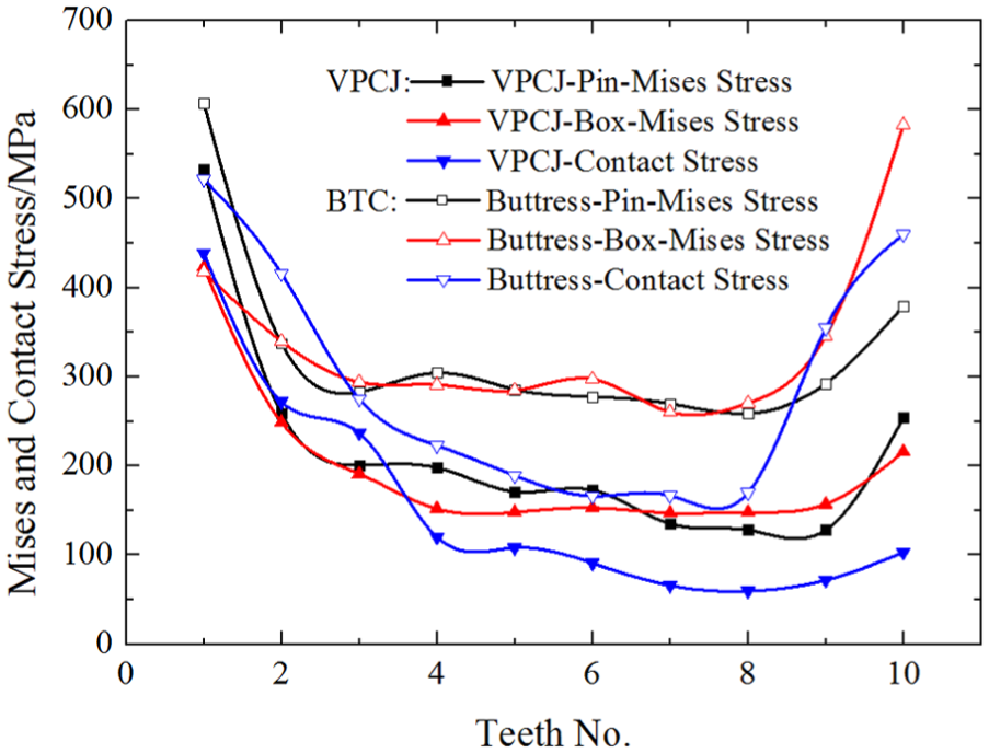
Mises and contact stress of teeth under tension load.
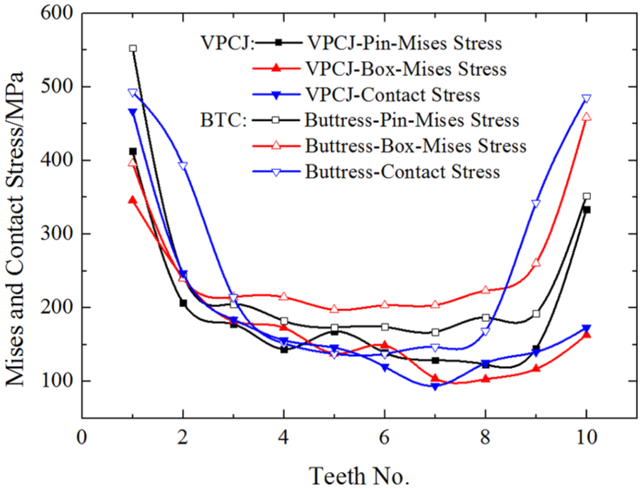
Mises and contact stress of teeth under compression load.
The maximum stress of the two kinds of casing joints occurs at the thread root of the first tooth in the pin, subjected to the tension load 2050 kN or the compression load 2050 kN. It can be seen from Figures 10 and 11 that the maximum stress distribution in each tooth of the two kinds of casing joints presents as saddle shape, the stress in the first tooth and the last tooth of the buttress casing thread are excessively high, and the trend of saddle shape is more obvious. But the variable pitch structure, increased threads cross-sectional area in front of threads teeth, can improve bearing strength effectively. The peak stress in front of teeth and the last few teeth are reduced obviously; meanwhile, the stress levels of the teeth in the middle are also significantly reduced. Under the tension load and the compression load, the bearing load surfaces are different, and the peak stress of thread joint appears different, resulting in compression capacity of the VPCJ being higher than tension capacity of the VPCJ, which also is beneficial to exert weight on bit (WOB) and torque load to run casing joint. The variable pitch structure can improve the bearing strength, and the peak stress of the first tooth is reduced. Its ability to resist deformation has been improved by means of decreasing the cross-sectional area in the last few teeth, which lowers the stress levels in the teeth, especially the stress levels in the first tooth and the last tooth, and improves the whole tension performance and compression performance greatly. Under the axial loads 2050 kN, the buttress casing thread has already yield, and the VPCJ still has not yield. The tension performance of the VPCJ is 37.8%, which is higher than that of the buttress casing thread. Compression performance of the VPCJ is 32.4%, which is higher than that of the buttress casing thread. Through the calculation of the axial load, the ultimate load capacity can be obtained. The maximum depth that the casing can reach can be calculated combined the basic physical properties of VPCJ. The maximum compression load applied on the top drive for casing running system can obtain.
Mechanical behavior of the VPCJ under bending load
Beading performance of the VPCJ has been studied subjected to a certain torque load with casing 40°/30 m borehole curvature load, the stress distribution in each tooth of casing joints and the contact stress distribution curve are shown in Figure 12.
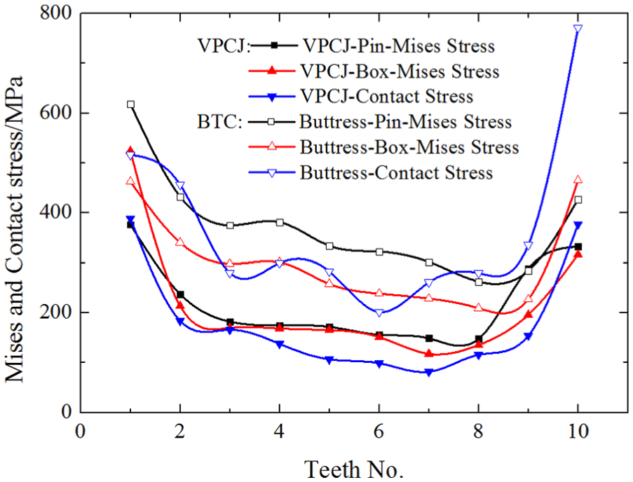
Mises and contact stress of teeth under bending load.
With the borehole curvature 40°/30 m, the maximum stress of the VPCJ appears in the first tooth of the box, and the maximum stress of buttress joint thread appears in the first tooth of the pin. The stress distribution and the contact stress distribution in each tooth of the VPCJ presents as higher at both ends of the teeth and small in the middle, and the last two teeth bear higher bending load. When bending load occurs, one side of the thread joint is in tension, and the other side is in compression. The areas with high contact stress and Mises stress are mainly concentrated on the tension side. Mises stress and contact stress are unevenly distributed along the circumference direction. The tension side areas with higher stress concentration are higher than that of the compression side areas; the stress distribution asymmetry in buttress casing joints is more obvious. The thread’s cross-sectional area of variable pitch structure changes constantly along the direction of helix. When bending load is applied, the bearing load surface has increased, resulting in lowering peak load effectively, and meanwhile, due to uneven distribution of Mises stress and contact stress, increasing the stress area reduces the possibilities of thread failures and seal failure and improves the collapsing strength. Under the bending load 40°/30 m, the maximum stress of the VPCJ is 524 MPa approaching yield strength, and the maximum stress of the buttress casing thread is 618 MPa exceeding yield strength. Bending performance of the VPCJ is 17.9% higher than that of the buttress casing thread.
Table 3 shows the increasing performance of VPCJ compared to buttress casing under loads. It shows that the torque performance, tension performance, compression performance, and bending performance of the VPCJ increased by 22%, 37.8%, 32.4%, and 17.9%. VPCJ plus the ability to push down while rotating and circulation helps to get the strings to the bottom. Moreover, for the ultrahigh-torque VPCJ, the number of thread teeth has less than other API round casing joint; the speed and efficiency are higher to make-up. VPCJ is used successfully on the top drive for casing running system, the largest hole deviation angle of 55.37°, torque of 40,000 Nm, when API round casing and buttress casing is failure under the same working condition.
The comparison of VPCJ and buttress casing.

Parameters sensitivity evaluation of the VPCJ structure
Based on initial VPCJ thread, considering the impact of torque load, influence rules of the key thread parameters on the torque performance are studied, considering that the variable pitch structure has the greatest influence on the first tooth. The stress distribution on the first turn of threads teeth is analyzed under torque load 40,590 lb ft.
Influence rules of the taper of the box and mount of variable pitch on torque performance
Figure 13 shows that the taper of the box has less influence on the stress of joint threads (less stress amplitude change of key threads teeth). The maximum stress of different tapers are little different. The maximum stress is 532 MPa, and the minimum stress is 510.2 MPa, and the stress distribution on the first turn of the thread teeth is even. Considering the influence of teeth height and wall thickness, the teeth height in front of the teeth and wall thickness will decrease with the increase of the taper in the box, resulting in the decreasing of bearing capacity, then fracture or thread slipping could occur during construction stage. Meanwhile, the increase of the taper will reduce contact areas and cause seal failure. It is suggested that smaller taper of the box is chosen as far as possible, recommended that the taper of the box is maintained at the range 1:11–1:13 to meet the bearing capacity to ensure thread contact areas and to reduce the risk of seal failure.

Stress distribution on the first tooth for different tapers of box and mounts of variable pitch.
It can be seen from Figure 13 that, the amount of varying pitch has significant influence on the bearing strength of joint threads. Under different amounts of varying pitch, the stress distribution is larger fluctuation. With the increase of the amount of varying pitch, the stress in the joint threads gradually decreases. When the amount of varying pitch is small (0.28 and 0.33 mm), the peak stress in the first tooth is 587.2 and 579.1 MPa, respectively, which have exceeded the yield strength. While the decrease of amount of varying pitch, threads cross-section area of the first few teeth in the pin will increase, but threads cross-section area in previous two teeth in the box is excessively small, leading to the significant increase of the stress in the first few teeth in the box. It cannot enhance bearing strength of joint threads. With the increase of the amount of varying pitch, threads cross-sectional area in the first two teeth in the box will increase, which can improve high stress problem in first tooth; but threads cross-sectional area of the last tooth in the pin will be lower. The stress in the first tooth and the last tooth in the pin will increase greatly, which is not conducive to the enhancement of joint bearing strength. Therefore, it is recommended that the amount of varying pitch of VPCJ should be larger, and the recommended amount of varying pitch should be in range 0.38–0.48 mm.
Influence rules of GSA and BSA on torque performance
BSA and GSA of the buttress joint thread is 3° and 10°, respectively. Figure 14 shows that the fluctuation of stress in VPCJ thread is high considering BSA, and the fluctuation of stress is low considering GSA. When the BSA is small (3° and 5°) and the stress is about 600 MPa, it exceeds yield strength and may cause thread failure. The peak stress in the first tooth in the pin will increase with the increase of GSA, but the increase amplitude is lower. The larger the increase of GSA is, the better the bearing performance of VPCJ is. Considering the joint threads in the form of variable pitch, threads cross-sectional area of the last tooth should be guaranteed to a certain width, thus the width of thread crest and thread bottom cannot be small. The GSA and BSA should be reverse angled as far as possible and angle values cannot be excessively large. Taking all factors into consideration, GSA and BSA should be chosen larger to improve the strength of the joint thread, meanwhile, to prevent the joint thread failure because of high stress value. It is recommended that GSA is in range 6°–10°, BSA is in range 7°–11°.

Stress distribution on the first tooth for different guide surface angles and bearing surface angles.
Field applications
In this article, ultrahigh-torque VPCJ (as shown in Figure 15) have been used eight times in several blocks of oil field in China, about 400 tons, downed to the maximum depth of 4375 m, the largest hole deviation angle of 55.37°, and horizontal section length of about 260 m. Under torque of 40,000 Nm, top drive rotated down into the gas well successfully without failure, and in the construction process, make-up speed is higher and works are more efficient.

Picture of the VPCJ products: (a) pin of the VPCJ and (b) box of the VPCJ.
Conclusion
It is the insufficient torque performance of casing joint that greatly restricted the application and dissemination of the top drive for casing running system. This article, presented a variable pitch ultrahigh-torque VPCJ thread–based screw transformation matrix, established a 3D numerical simulation model of VPCJ based on the virtual work principle and the large deformation theory, optimized the main structure parameters with the judgment of torque-bearing capacity under loads, and analyzed the mechanical behavior and the parameter-sensitivity evaluation. The following conclusions are drawn from this study:
The variable pitch helix is established based on the theory of screw transformation matrix. A preliminary design scheme of VPCJ generates in the form that the helix is designed as the variable pitch helix.
A 3D numerical simulation model of VPCJ is established based on theory of virtual work and large deformation theory. The accuracy of the model is verified based on experimental data.
Based on the 3D whole structure FEM of the VPCJ, orthogonal optimization of key structural thread parameters of the VPCJ is calculated. It is concluded that the influence order of factors on the torsional capacity is GSA, BSA, amount of varying pitch, the pitch of box, and the first teeth width of pin (B > A > D > C > E). Within the scope of study, the optimal combination of the VPCJ is as follows: GSA (8°), BSA (11°), amount of varying pitch (0.48 mm), the taper of the box (1:13), and the first teeth width of pin (6.11 mm).
The stress distribution and deformation coordination have been calculated under tension, compression, bending load, and torque load and compared to stress distribution and deformation coordination of the buttress casing thread. The torque, tension, compression, bending, and capacity of the VPCJ is 27.8%, 37.8%, 32.4%, and 17.8%, respectively, more than that of the buttress joint thread.
Influence rules of critical parameters including BSA, GSA, amount of varying pitch, and the taper of the box on the torsional resistance are studied. Analysis shows taper of the box has a great influence on the number of thread teeth, which can affect the bearing performance and sealing performance. The recommending thread taper of the box maintains in range 1:11–1:13. The amount of varying pitch has a great influence on the bearing performance. The recommending amount of varying pitch is 0.38–0.48 mm, GSA of 6°–10°; and BSA of 7°–11°.
Footnotes
Handling Editor: Jining Sun
Declaration of conflicting interests
The author(s) declared no potential conflicts of interest with respect to the research, authorship, and/or publication of this article.
Funding
The author(s) disclosed receipt of the following financial support for the research, authorship, and/or publication of this article: This research is supported by the Open Fund (grant no. OGE201702-27) of Key Laboratory of Oil &Gas Equipment, Ministry of Education (Southwest Petroleum University), the Scientific Research Starting Project of SWPU (grant no. 2017QHZ012), the Major Project by Education Office of Sichuan Province (grant no. 17ZA0418), the Natural Science Fund (grant no. 51674214), the Youth Scientific Research Innovation Team Project of Sichuan Province (grant no. 2017TD0014), and the International Cooperation Project of Sichuan Science and Technology plan (grant no. 2016HH0008).