
Abstract
In this study, it was aimed to operate today’s compression ignition engines easily in dual-fuel mode with a developed electronic control unit. Especially, diesel engines with mechanical fuel system can be easily converted to common-rail fuel system with a developed electronic control unit. Also, with this developed electronic control unit, old technology compression ignition engines can be turned into dual-fuel mode easily. Thus, thanks to the flexibility of engine maps to be loaded into the electronic control unit, diesel engines can conveniently be operated with alternative gas fuels and diesel dual fuel. In particular, hydrogen, an alternative, environmentally friendly, and clean gas fuel, can easily be used with diesel engines by pilot spraying. Software and hardware development of electronic control unit are made, in order to operate a diesel engine with diesel+hydrogen dual fuel. Finally, developed electronic control unit was reviewed on 1500 r/min stable engine speed on different hydrogen energy rates (0%, 15%, 30%, and 45% hydrogen) according to thermic efficiency and emissions (CO, total unburned hydrocarbons, NOx, and smoke), and apart from NOx emissions, a significant improvement has been obtained. There was no increased NOx emission on 15% hydrogen working condition; however, on 45% hydrogen working condition, a dramatic increase arose.
Introduction
Despite the fact that oil reserves will drain away in the near future, fuel demand is increasing in many sectors, especially in transportation. Because of that reason, European Union Commission has been promoting environmentally friendly, clean, and alternative energy sources usage and expects that greenhouse gas emissions decrease by 60% in 2050. 1 However, while European Union has been taking measures, renewable energy consumption is still on very low levels. Especially in recent years, diesel engines are known to cause significant damage to the environment due to NOx and smoke emissions.2–4 In order to lower NOx and carbon emissions, after treatment systems have been used in diesel engines. However, catalyst materials are highly expensive and current technology cannot afford stringent emission regulations. Thus, turning to alternative energy sources such as liquefied petroleum gas (LPG), compressed natural gas (CNG), liquefied natural gas (LNG), biogas, and biodiesel has become more widespread in the recent years.5–15 Hydrogen, among the other alternative energy sources, comes to the forefront by its clean and environmental friendly properties. It is not possible for electric hybrid vehicles to be used widely in near future with the current technology. 16 Hydrogen can be used as a short-term solution on transition to electrical vehicles. 17
Although in some studies18,19 hydrogen has been used as a fuel in homogeneously filled compression ignition engines (homogeneous charge compression ignition (HCCI)), they are not commercially viable due to combustion problems. In some studies,20,21 hydrogen has been used on gasoline engines; however, there has been backfiring combustion problems obtained. Karagoz et al. 22 used hydrogen and oxygen as additional fuel sent into a four-stroke Otto engine, and it is obtained that the CO and total unburned hydrocarbons (THC) emissions are reduced.
Some researchers have used methane and hydrogen fuels on engines.23,24 Huang et al. 25 have worked on methane and hydrogen gas fuels’ cyclic variations revolutionary differences.
Despite compression ignition (CI) engines’ high compression rates and high thermal efficiency advantages, they make NOx and smoke emissions worse.26,27 Considering after-treatment devices’ high prices, hydrogen’s usage in diesel engines is more reasonable. 28 In order to combust hydrogen, another energy source is required. 29 For instance, Ikegami et al. 30 used glow plugs to heat up intake air to create better hydrogen combustion.
Another method is to use hydrogen injectors from intake port to send hydrogen and to keep it with pilot diesel spray.31–33
The studies on the use of hydrogen in diesel engines are presented below. H-W Wu and Z-Y Wu 33 operated CI engine on 1800 r/min constant engine speed, sent different rates of hydrogen, and found out that CO and smoke emissions have decreased with hydrogen addition. Pan et al. 32 sent three different rates of hydrogen on a two-stroke diesel engine and obtained an improvement on CO and smoke emissions. Miyamoto et al. 16 sent hydrogen in a diesel engine and investigated the effect of hydrogen addition on exhaust emissions.
Although high pressure direct hydrogen injectors cannot be found in market, modifying current engines is almost impossible because machining on cylinder head is necessary and engine constructions may not be suitable for this conversion. On the other hand, continuous hydrogen sending is not a reliable method, and some combustion problems such as backfire and pre-ignition will be observed. 2 Also, it is impossible to meet stringent emission regulations. Furthermore, the fuel consumption of the engine is another challenge for continuous hydrogen introduction. Therefore, using gas injectors and developing an electronic control unit (ECU) is an obligation for dual-fuel engines.
Some researchers’ studies about developing ECU for dual-fuel engines are given here. Gettel et al. 34 built a dual-fuel diesel–natural gas control system for heavy trucks. Zhang et al. 35 developed an ECU for dual-fuel diesel–CNG engine using an MC68HC811A1 microcontroller, and Oliveira et al. 36 developed an ECU for hydrogen injection in a diesel power generator.
Although there are lots of studies about experimental tests on hydrogen and diesel dual-fuel combustion in CI engines, there are no studies which investigate ECU development, performance, and emission effects of developed ECU on CI engine. In this study, first an ECU which can control both hydrogen and diesel injectors is developed. Both hardware and software of the ECU are investigated. Then, a test is performed on a CI engine. In this study, different levels of hydrogen (0%, 15%, 30%, and 45% on energy basis) were used with diesel fuel at 1500 r/min engine speed and full engine load. Using the self-developed ECU, hydrogen was introduced from the intake manifold and diesel injectors were controlled with the same ECU. The injection durations and injection advance on both injectors (diesel and hydrogen) was controlled by easily developed ECU. Using this method, old technology diesel engines can be easily converted into new technology dual-fuel mode in which both injectors are electronically controlled.
Testing set
In Figure 1, testing sets’ schematic projection is shown. A single-cylinder engine with a mechanical diesel fuel system is turned into a common-rail system. Instead of mechanical injectors, diesel injectors with the same spray angle were used. The fuel used is of EN 590 standards and the hydrogen used is 99.99% pure. With a miniature oval gear type, flow meter diesel fuel consumption is measured.

Schematic of the testing set.
Diesel engine and the engine dynamometer
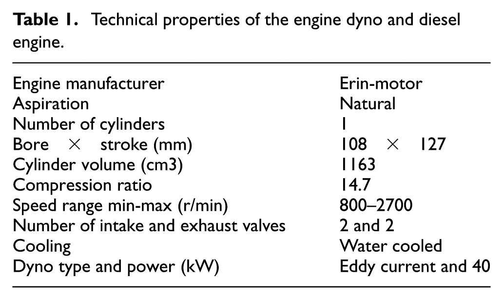
Self-developed ECU was used on 1.16 L, naturally aspirated, four-stroke, direct injection CI engine. The diesel engine was developed by Erin motor and Yildiz Technical University. A water cooling type Eddy current dynamometer was used to load the CI engine in Yildiz Technical University, Internal Combustion Engines Laboratory. The technical properties of diesel engine and engine dynamometer are presented in Table 1.
Technical properties of the engine dyno and diesel engine.
Engine control system structure
Engine control system designed and developed in this work consists of two main sections: power transformation section and injection control section. In the power transformation section, 12-V DC electrical power available is provided to develop DC to AC convertor board. This board outputs AC electrical power to a transformer where the voltage is increased from 12 to 50 V. Output of the transformer is fed to an AC to DC convertor board. High-voltage DC power is available at this point to be used by diesel injector.
Injection control section includes a main control unit, sensors that are providing input signals to the control unit, and driver boards controlling injection actions. Pedal sensor transmits a signal to the control unit indicating current position of the pedal. Using the signals that are transferred from the respective sensors, camshaft position and crankshaft speed are detected by the control unit. Diesel and gas injection signals, determined by the control unit, are sent separately to each injector’s driver board. Driver boards convert incoming low-voltage signals to higher voltage electrical power sent to injectors. Figure 2 shows the system structure and connections between main sections.

Engine control system structure schematic, demonstrating components of the system and their connectivity.
Hardware structure
Current engine control system uses an Arduino Due microcontroller board as the control unit section. This microcontroller has a clock speed of 84 MHz which enables it to handle all the data collection from sensors, internal computations, and signal emission in a timely manner. It has a built-in analog to digital convertor (ADC), 512 KB of Flash memory, and 96 KB of SRAM. Analog output of the pedal sensor in the system is directly captured by the ADC and converted to digital signal understandable by the microprocessor. To detect speed of the crankshaft and camshaft position, an inductor proximity sensor is located on the side of a metal ring which is mounted on the engine shaft. The metal ring is fabricated to have a specific gear shape teeth all around it, with a distinct teeth pattern at one point to represent the top dead center (TDC) position. These digital signals are acquired by the Arduino digital input pins. To generate high-voltage electrical power required for diesel injector, power transformation boards have been developed. Schematic of the electrical circuit of the boards is shown in Figure 3. A NE555 timer creates oscillatory signal with a frequency of 100 Hz which can be adjusted by the variable resistor. A CD4013 CMOS dual D Flip-Flop then divides this signal into two trains of pulses with equal frequency but 180 degrees phase difference. These pulse currents control two IRL2203N MOSFETs which create a 50 Hz AC power. The AC power is fed to a transformer and the higher voltage output of transformer is rectified and filtered to create a 50-V DC power output.

Schematic of 12–50 V DC to DC power transformation circuit.
Driver boards have been designed and developed to control injectors’ functionality. Figure 4(a) shows diesel injector driver board’s circuit schematic. This board is designed to be controlled by two separate signals, each controlling injection with a different voltage. A higher voltage injection is performed initially to accelerate the response of the injector, and a lower voltage injection keeps the injection active for the rest of injection period. For either high- or low-voltage section of this board, a MOSFET (metal-oxide semiconductor field-effect transistor) is used to apply the received signal from control unit and control another MOSFET which triggers the injection. Gas injector driver board design is shown in Figure 4(b). Gas injector is triggered using only 12 V electrical power and one MOSFET transfers control signal command to the injector.

(a) Schematic of diesel injector driver board’s circuit and (b) schematic of gas injector driver board’s circuit.
Software system
Developed ECU uses a set of look-up tables to capture the injection parameters including injection duration and injection advance values. In software of internal combustion engines, usually two- or three- dimensional tables are used to control engine parameters. In these types of tables, depending on the Revolutions Per Minute (RPM) of the engine and the accelerator pedal position, fuel injection properties are determined. A three-dimensional type look-up table is used, where first and second dimensions are RPM of the engine and accelerator pedal position, and third dimension is the fuel injection properties. These look-up tables are stored in the control unit of flash memory. The look-up tables are obtained from experimental studies in a single-cylinder direct injection diesel engine in Yildiz Technical University, Internal Combustion Engines Laboratory. Figure 5 shows sections of look-up table used in the control system, where relationships between engine load, engine speed, and fuel injection durations are displayed. Similar relationships exist for fuel injection advances and the amount of gas proportion.

Graphical representation of sections of the look-up table used in the control system: (a) gas injection duration for given engine powers and engine speeds and (b) diesel injection duration for given engine powers and engine speeds.
Control software includes two main sections: a setup section where initializations of all variables and interrupt service routines are performed and a main loop section where all the functions are executed. Two interrupt service routines are used in the software. Interrupts duty is to capture the incoming data from the proximity sensor in parallel to the other functionalities being executed in the software. The first interrupt uses the proximity sensors output to determine RPM. The second interrupt is responsible to detect when the engine reaches to the TDC position. It is very critical not to miss the TDC and that is the main reason an interrupt is used for this purpose. The main loop section of the software has two main operation modes. While the TDC position is not detected in the current engine cycle, the software reads the incoming data from the sensors, calculates RPM, and maps the pedal sensor value to the demanded torque range of the look-up table. Immediately after interrupt routine detects TDC position is reached, the software enters its second operation mode. In this mode, data acquisition is stopped to use maximum computational speed available in the control unit for precise injection operations. It is in this mode that three-dimensional regression on the look-up table is performed and proper gas and diesel injection parameters are calculated. These calculations are performed only once in each engine cycle to optimize speed efficiency of the software. Figure 6 explains the logic of the control software in a flowchart diagram.

Simplified flowchart of the control software.
Gas fuel line
Hydrogen fuel line schematic is illustrated in Figure 7. A high-pressure Linde brand gas tank was used as hydrogen fuel source. A hydrogen pressure regulator was installed to the hydrogen line. A quick-connect which can be used as a check valve is installed to the fuel line. Moreover, a relief-valve was installed. An electromagnetic hydrogen gas injector was installed to the diesel engine manifold. The other pieces of equipment which are installed to the line can be seen from the schematics.

Schematic of the hydrogen line.
Exhaust gas emission measurement
An AVL brand 415S type smoke analyzer was used to determine accurate smoke value of the engine exhaust gases. CO, THC, and NOx emissions were measured using an AVL brand Digas 4000 type emission analyzer.
The engine operation
The CI engine has been activated on 1500 r/min stable speed according to ESC on C speed point. Different amounts of hydrogen (0%, 15%, 30%, and 45%) have been sent to engine. 0% hydrogen shows only diesel operation conditions. Four different hydrogen energy fractions which are 0%, 15%, 30%, and 45% were selected. 0% hydrogen energy fraction represents neat diesel operation condition. The hydrogen energy fraction could not exceed 45% due to backfiring. 15% hydrogen energy fraction was tested as small amount of hydrogen addition. Also, 30% hydrogen energy fraction was used. All tests are conducted under full working load conditions, and during the tests, engine speed and torque have been stabilized. Test conditions are summarized in Table 2. Accuracies and uncertainty analysis are given in Table 3.
The summary of test conditions.
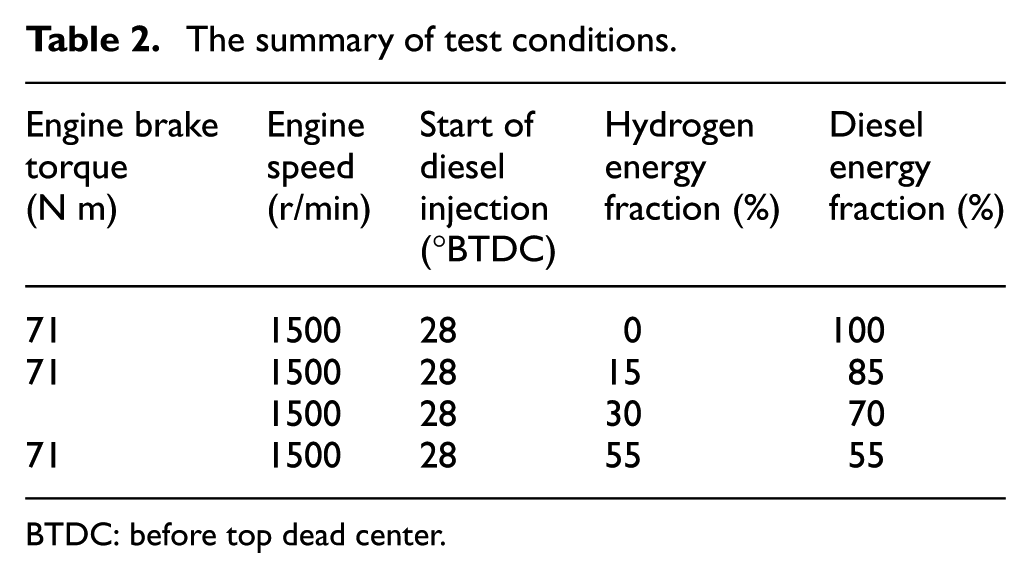
BTDC: before top dead center.
Measurement accuracies and calculated uncertainties.

Results and discussion
In the study that has been conducted in Yildiz Technical University, Internal Combustion Engines Laboratory, diesel–hydrogen dual-fuel system has been tested on the test engine under 1500 r/min stable engine speed and 71 N m stable engine torque (full load condition). The hydrogen fuel was injected into the test engine using electromagnetic hydrogen injectors. A self-developed hybrid ECU which controls both diesel and gas injectors was used to operate the engine in dual-fuel mode. Thanks to developed ECU, all diesel engines can be easily operated in dual-fuel mode. The design and schematics of the proposed ECU describe single-cylinder engine control structure. Although the exact same electronics and hardware structure can be repeated to control higher number of cylinders, the only limitation of the number of cylinders is the microprocessor’s speed which should be able to handle all the operations in time. With the microprocessor described in this study, up to four cylinders have been tested to work in a timely manner. A sample output signal of the developed ECU for both gas injection control and diesel injection control is recorded and displayed in Figure 8. Expected injection properties, engine speed, and engine load based on which output signals are generated are mentioned in the figure. The diesel injector injection advance is 28° BTDC (before top dead center). Also, the gas injector advance is 0° TDC. The diesel injection pressure was set to 1000 bar. The hydrogen gas injection pressure was set to 5 bar. The injection duration of diesel injectors are 1.5, 1.34, 1.23, and 1.14 ms for 0%, 15%, 30%, and 45% hydrogen addition, respectively. The hydrogen gas injection durations are 0, 4218, 5826, and 8318 µs for 0%, 15%, 30%, and 45% hydrogen addition, respectively. C operation speed was selected according to ESC procedure.
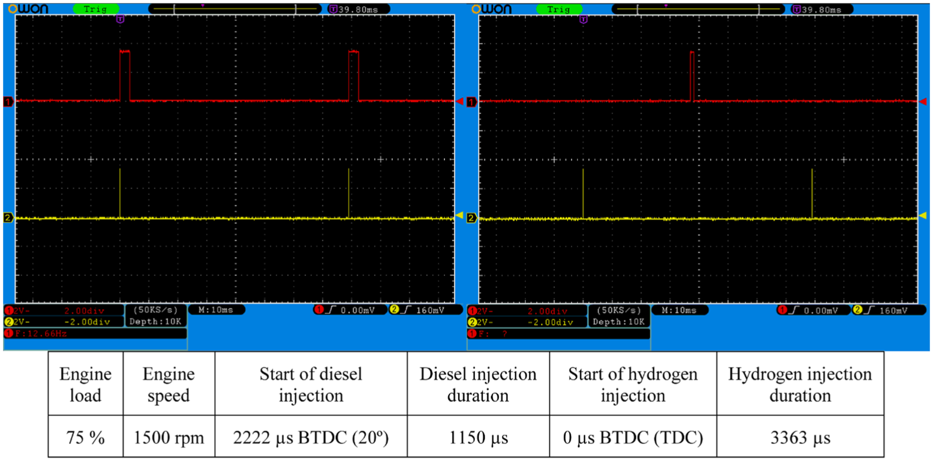
ECU output signal test results for specific values given.
The engine brake thermal efficiency is the rate of engine power output on fuel energy consumption. It shows how much of the fuel energy can be converted into useful energy. 37 Figure 9 shows the effect of different levels of hydrogen energy fraction on engine brake thermal efficiency. The brake thermal efficiency values are 24.67%, 24.75%, 24.89%, and 24.98% with 0%, 15%, 30%, and 45% hydrogen addition, respectively. With the addition of hydrogen, brake thermal efficiency values’ percentile improvement rates are, respectively, 0.32%, 0.89%, and 1.26%. Hydrogen’s flame speed is quite higher than diesel fuel. Diffusion coefficient of hydrogen is higher than all other fuels. For this reason, the homogeneity of the combustible mixture is increased. Furthermore, the combustion efficiency improves with higher flame speed of hydrogen. Thus, the thermal efficiency increases with hydrogen addition.
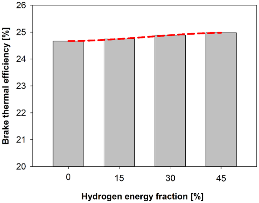
Effect of different levels of hydrogen energy fraction on engine brake thermal efficiency.
CO is a toxic and harmful exhaust emission and is a result of petrol fuels’ deficient and inefficient combustion. 38 The effect of different levels of hydrogen energy fractions on carbon monoxide emission is given in Figure 10. The CO emission values which are emitted from exhaust gases are 0.38% vol., 0.25% vol., 0.17% vol., and 0.16% vol. with 0%, 15%, 30%, and 45% hydrogen addition. The improvements in CO emissions are 34.2%, 55.3%, and 57.9% with 15%, 30%, and 45% hydrogen addition according to neat diesel (0% hydrogen addition). The hydrogen fuel does not involve carbon atom. Hence, the ratio of carbon to hydrogen in the fuel decreases with increasing hydrogen content. Moreover, the combustion efficiency increases with the high flame speed and high diffusion coefficient of hydrogen.

Effect of different levels of hydrogen energy fraction on carbon monoxide emission.
Hydrocarbons are released by inefficient combustion of hydrocarbon-based fuels. On internal combustion engines, unburned hydrocarbons that are exhausted out are called unburned total hydrocarbons (THC). 26 The effect of different levels of hydrogen energy fractions on total hydrocarbon emission values is shown in Figure 11. The total hydrocarbon values are 23, 19, 17, and 15 ppm with 0%, 15%, 30%, and 45% hydrogen addition, respectively. With 15%, 30%, and 45% hydrogen addition, improvement on THC emissions compared to only diesel fuel is 17.4%, 26.1%, and 34.8%. Main reasons of decrease in THC emission are hydrogen’s high flammability rate and high diffusion coefficient properties which lead to increase efficiency of combustion.

Effect of different levels of hydrogen energy fraction on total hydrocarbon emission.
Nitrogen oxides (NOx) comprise nitrogen monoxide (NO) and nitrogen dioxide (NO2). Nitrogen oxides (NOx) and especially NO is highly harmful for environment and creatures. Nitrogen oxides’ formation can be explained by two essential mechanisms: thermal mechanism (Zeldovich mechanism) and prompt mechanism (Fenimore mechanism). The NO formation is performed according to Zeldovich mechanism. Hence, NO formation is dependent on in-cylinder temperature and oxygen availability.39,40 In Figure 12, the effect of different levels of hydrogen energy fractions on oxides of nitrogen emissions has been given. The nitrogen oxides’ values are 2016, 2019, 2157, and 2895 ppm with 0%, 15%, 30%, and 45% hydrogen addition, respectively. The increase in NOx emissions are 0.14%, 6.99%, and 43.60% with 15%, 30%, and 45% hydrogen addition, respectively. Flame temperature of hydrogen is higher than that of other fuels. In-cylinder temperature increases with hydrogen addition. Also, the combustion duration is shortened with hydrogen addition. With the high diffusion coefficient of hydrogen fuels, homogeneity increases; therefore, oxygen availability also increases. Thus, a dramatic increase in NOx emissions is observed with hydrogen addition.

Effect of different levels of hydrogen energy fraction on oxides of nitrogen emissions.
Particulate matters are generated from carbonaceous materials. Carbonaceous materials are formed due to incomplete combustion and lack of oxygen. Figure 13 shows the effect of different levels of hydrogen addition on smoke emissions. The smoke emission values are 0.51, 0.35, 0.26, and 0.20 FSN with 0%, 15%, 30%, and 45% hydrogen addition, respectively. The improvement values in smoke emission according to neat diesel are 31.2%, 48.9%, and 60.7% with 15%, 30%, and 45% hydrogen addition, respectively. A novel improvement is obtained with increasing amount of hydrogen. Hydrogen does not contain carbon atoms, so the carbon/hydrogen ratio drops and the homogeneity of combustible mixture increases. Thus, the smoke emissions significantly improve with the addition of hydrogen.

Effect of different levels of hydrogen energy fraction on smoke emission.
Conclusion
In this study, first an ECU development was done to easily convert CI engine which has mechanical fuel system into electronically controlled dual-fuel engine. Second, engine tests were done using self-developed ECU. Tests were conducted at 1500 r/min engine speed and full load (100%) engine operation condition. Hydrogen energy fraction levels (0%, 15%, 30%, and 45% on energy basis) were tested in the test engine.
The obtained brief results are summarized below:
A simple ECU software and hardware were developed for easily converting conventional CI engines into dual-fuel engines. Thanks to simple control strategy of the ECU, old technology CI engines can be easily converted into high-technology dual-fuel engines which have common-rail system and electronically controlled gas fuel system.
Using self-developed ECU with hydrogen and diesel fuels in the old CI engine, the brake thermal efficiency of the engine was improved 0.32%, 0.89%, and 1.26% with addition of 15%, 30%, and 45% hydrogen as energy fraction, respectively.
An important improvement was obtained on both CO (up to 57.9%) and THC (up to 34.8%) emissions thanks to superior properties of hydrogen. However, the dramatic increase in NOx emissions could not be averted. Also, a novel improvement in smoke emissions (up to 60.7%) was obtained.
According to this study, using self-developed ECU which has simple and easy control strategy in old technology CI engines, an important recovery will be obtained in the engine performance and emissions.
Footnotes
Acknowledgements
The authors are indebted to Şahin Metal A.Ş. and Erin Motor for test apparatus and equipment donation.
Handling Editor: Jose Ramon Serrano
Declaration of conflicting interests
The author(s) declared no potential conflicts of interest with respect to the research, authorship, and/or publication of this article.
Funding
The author(s) disclosed receipt of the following financial support for the research, authorship, and/or publication of this article: This research was supported by TUBITAK (Scientific and Technological Research Council of Turkey) with 1512 project (Project Number: 2150175). M.M.S. has been financially supported by TUBUTAK 2215 program.