
Abstract
The internal mixer is an important devise for processing the polymer nanocomposites acting as a chemical reactor. In this article, based on the computational fluid dynamics method, the fluid transportation and heat transfer analysis of sol–gel reaction processing for Polypropylene (PP)/TiO2 nanocomposites in the internal batch mixers with single-winged and two-winged Cam rotors were simulated. First, the Lagrangian coherent structure analysis was used to understand the fluid transport properties in the mixers. Then the effect of rotational speeds (ratios) and barrel temperatures on the heat transfer characteristics in the mixers with different rotors was analyzed. Also, the changes of viscous heating and torques of rotors with different thermal conditions in the mixers were discussed. Especially, the relationship between the fluid transportation and heat transfer characteristics was explored. The results show that a big rotor speed ratio can induce great fluid transportation in the left and right mixer chambers based on the Lagrangian coherent structure analysis, and the fluid near the horseshoe map has great folding effect and temperature magnitude. The viscous dissipation, viscous heat generation, and rotor torques in the mixers increase with increasing the rotational speeds and decrease with increasing the barrel temperatures. The mixer with two-winged rotors has higher average temperature, viscous dissipation, viscous heat generation and the torques of rotors values of reactive fluid than that with single-winged rotors.
Introduction
The internal mixer with asynchronous rotors is an important equipment of polymer industry due to its high mixing efficiency. Recently, the internal rotating mixers have been utilized to process the polymer nanocomposites acting as a batch chemical reactor, typically for processing Polypropylene (PP)/TiO2 nanocomposites.1–3 The PP/TiO2 nanocomposites are often processed using in situ sol–gel reaction method into the internal mixer and have more excellent material properties than the PP polymer, for example, mechanical properties, flame retardance, and thermal stability.4–6 Meanwhile, the rotor geometric has great influence on the mixing efficiency in the internal mixers, which controls the situ sol–gel reaction to determine the quality of nanocomposites.
As is known to us, the reactive extrusion in the internal mixer is a complicated process controlled by many variates. Meanwhile, because the viscous fluid is highly non-isothermal induced by heat transfer, viscous dissipation, and chemical reactions, the temperature distribution in the mixer is an important factor to determine the reactive processing and product quality. For example, when the temperature distributions in the mixer increase, the rate of reaction increases, 7 and the size range of formation particles decreases. 8 Especially, comparison with traditional polymer processing in twin screw extruders, the nanocomposites processing in the mixer required higher shears rate and longer residence time distributions to obtain nanoscale dispersion. 9 Therefore, understanding the temperature distribution rules in the internal mixer is important to carefully control rates of ongoing chemical reactions.
With the recent advances in computational fluid dynamics, the finite element method (FEM) has been a useful tool to better understand the temperature distribution in complex geometries. Lots of researchers focused on the heat transfer of nonreactive polymer processing in the mixer using two-dimensional (2D) or three-dimensional (3D) non-isothermal models.10–15 Typically, Campanelli et al. 13 developed kinetic, thermodynamic, and rheological equations to calculate batch temperature, torque, and power consumption in an internal mixer. Ishikawa et al. 14 developed a 3D steady-state non-isothermal models to analyze the temperature profiles in a nonintermeshing continuous mixer using the FEM. Bai et al. 9 established a transient and non-isothermal model to simulate the heat transfer process in an internal mixer using commercial software, Polyflow. The temperature distribution and the heat transfer between polymer melt and mixer wall were obtained. Salahudeen et al. 15 optimized the rotor speed according to stretching, efficiency, and viscous heating in an internal mixer with Cam rotor using 2D finite element modeling. The temparature rise between the Cam rotor edge and mixer wall was analyzed.
The analysis of reaction process in the internal mixer is very complicated due to the nonlinear and couple effect of flow-heat transfer-reaction. Comparison with nonreactive polymer processing, the thermal analysis researches of reactive polymer inside the internal batch mixer are relatively limited. Zhou et al. 16 used Polyflow code to simulate the Polyethylene (PE) branching reaction in a Haake mixer using non-isothermal model, but the temperature information of the reactive system in the mixer was not given. Considering the viscous dissipation, Adragna et al. 7 established the closed equations of the flow, mass, energy, and momentum for polymer flowing in an internal mixer. The velocity and torque profiles considering heat transfer with time evolution were discussed. On the other hand, for the reaction in the mixer, most studies focused on the experiment product performance by experimental techniques.17–20 More recently, Zhu and Sun 21 studied the influences of chaotic flow fields induced by rotor speed ratios on the local and overall reactive rates in the mixer with Haake rotors. However, the information of complex reactive temperatures dominated by the fluid transportation and mixing efficiency in the internal mixers is relatively absent.
Recently, Lagrangian coherent structure (LCS) was proposed to identify the chaotic manifold in a dynamic system of fluid flow.22–24 The LCS provides a strong tool to analyze the potential chaotic mixing mechanism. The ridges of the finite-time Lyapunov exponent (FTLE) present the most stretching and repelling structures, which are called LCS. Parts of applications studied the mixing and transport process in the internal mixers using the FTLE and LCS.25–27 Robinson and Cleary 26 extracted the manifold structures from the forward and backward FTLEs with a rational integration time, and the mixing characteristics in different conditions were discussed using the LCS. Moreover, they used the same method to identify and visualize the 3D manifold intersections in a helical ribbon mixer. 27 Most studies focused the LCS applications in other subjects, such as the vortex pinch-off, 28 atmosphere, 29 ocean, 30 biology, 31 and electromagnetic. 32 However, the studies using the LCS to analyze the time-varying flow considering the effect of moving parts and fluid temperature are relatively limited.
In this study, based on the Computational Fluid Dynamics (CFD) method, the fluid transportation and heat transfer analysis of sol–gel reaction for PP/TiO2 nanocomposites are employed in the internal mixers with single-winged and two-winged Cam rotors, respectively. Based on the LCS analysis, the fluid transportation and transient heat transfer profiles in the reaction procession of preparing PP/TiO2 nanocomposites are simulated in the internal mixers with two types of Cam rotors. Especially, some relationship between the fluid transportation and heat transfer characteristics is employed. Moreover, the influences of rotor speed ratios and barrel temperatures on the heat transfer characteristics in the internal mixers are investigated. Specially, the changing rules of viscous heating and torques of rotors with different thermal conditions in the mixers are discussed.
Methods and materials
Mathematical modeling
The hydrolysis–condensation reactions of titanium alkoxides with sol–gel method in the internal mixer obey the overall generalized reaction as follows 1

To study above reactive flow in the internal mixers with different rotors, we adopt some assumptions as follows: (1) the flow in the mixer is non-Newtonian and laminar flow; (2) the internal mixer is fully filled with nanocomposite fluid; (3) the conditions of incompressible and non-slip of surfaces are considered.
The continuity and momentum equations are respectively expressed in equations (2) and (3) as follows 33

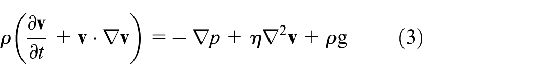
where
The energy conservation obeys the following equation 34

where T denotes the absolute temperature,
The stress tensor in equation (7) is written as follows

in which

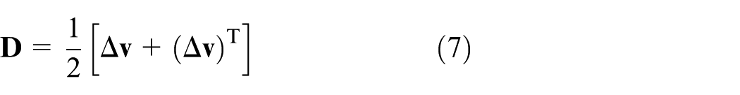
The form of the deformation tensor rate is defined as
In this study, the viscosity of the material is assumed to be equal to the PP matrix. The PP viscosity is described as Carreau–Yasuda and Arrhenius laws35,36

where
The key data of the material properties.

After the inorganic precursor entering the molten PP matrix, considering the effect of dilution on the PP matrix, the zero-shear viscosity

where
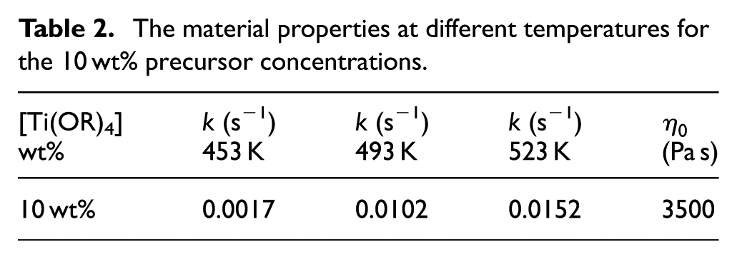
The material properties at different temperatures for the 10 wt% precursor concentrations.
The conversion rate of sol–gel process can be defined as

where
Based on the Arrhenius law, the kinetic constant, k, for this reaction is defined as

where
According to the rate of strain tensor, the viscous dissipation,

The torque acting on one rotor is defined as
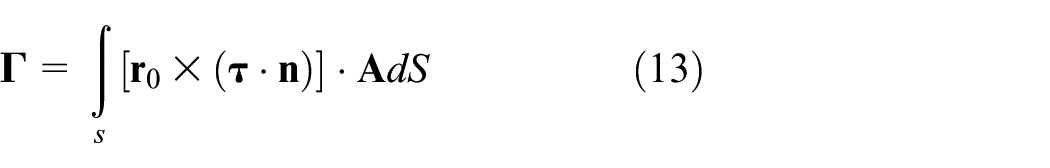
where
The velocity boundary conditions are given by
At the barrel wall

At the rotor surface

where
The temperature magnitude imposed at the barrel wall is given as

Numerical solutions
Two Cam rotors installed in the internal mixer have the counter-rotating speed with different speed ratios of left rotor to right rotor setting as 3:1, 3:2, and 3:3, respectively, as illustrated in Table 3. Usually, the Cam rotors have two types of structures, namely single-winged rotor and two-winged rotor, as illustrated in Figures 1 and 2, respectively. In order to study the fluid transportation and heat transfer characteristics in the unsymmetrical flow field, the phase angles between the rotor wings in both two types of rotors are all symmetrical. Considering the periodical geometric changes, the FE models of the two rotors and flow domains are established by terms of Gambit software with the mesh superposition technique. The quadrilateral cells are used to mesh the rotors and flow domains, as shown in Figures 1(b) and 2(b). In order to accurately capture the velocity gradients in the small clearances between the rotor and barrel walls and near the walls, three cell layers are employed in the FE model (see Figures 1(b) and 2(b)). Meanwhile, the FE model of two-winged rotors has 21,879 elements and 22,546 nodes, respectively. The time step, namely 160 steps/period, is chosen in our simulations considering the cost of computing. In addition, the grid independence test is employed and it proves that the mesh with 21,879 elements is sufficient to resolve the flow velocity properties.
Boundary conditions in the simulations.


Geometric and FE models of the mixer with single-winged rotors: (a) geometric model and (b) FE model.

Geometric and FE models of the mixer with two-winged rotors: (a) geometric model and (b) FE model.
Based on the generalized Newtonian approach, all simulations are carried out using a commercial CFD software, ANSYS Polyflow. In this work, the residual criteria of 10−4 are adopted for all the simulations. The details of temperature and flow boundary conditions for all simulations are illustrated in Table 3.
Calculations of FTLE and LCSs
The LCS proposed by Haller and Yuan 22 was used to describe the coherent structures of two-dimensional flow which defined as manifolds upon the dynamics. These manifolds are useful to understand the material transport from experimental and numerical flow data, especially explain the underlying mixing reasons of the high-viscosity fluid flow resulting in laminar flow.
Let us consider a two-dimensional flow dynamical system

where

Then a finite-time version of Cauchy–Green deformation tensor by displacement grads tensor form the trajectory

where
So, the FTLE with a finite integral time TLE can be defined as
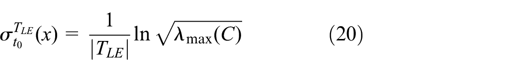
In which,
Based on the velocity field in the mixer calculated by Polyflow software, the fluid particle positions at the time t + TLE are located using the fourth-order Runge–Kutta scheme by MATLAB software. Then the spatial gradient
Results and discussion
Fluid transport characteristics
LCS is adopted to understand the fluid transport properties in the mixers. The forward-time FTLE maps in the mixers with different speed ratios of 3:3, 3:2, and 3:1 with integration time TLE = 30 s and initial time t = 0 s are shown in Figure 3(a)–(c), respectively. From this figure, the repelling LCSs in the forward-time FTLE maps are legible observed and the adjacent particles tend to rapidly deviate from these repelling LCSs.
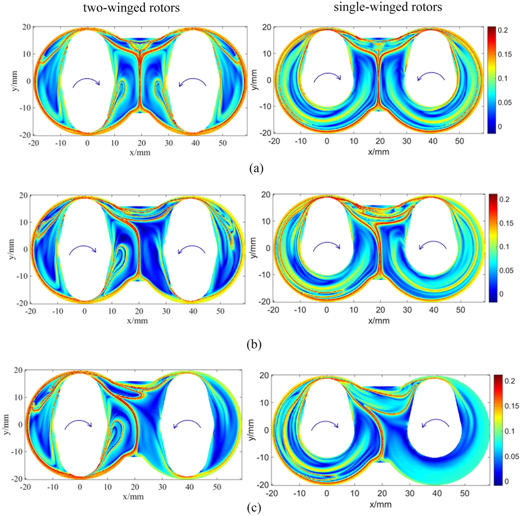
Forward-time FTLE maps in the mixers with two kinds of rotors at integration time T = 30 s with different rotor speed ratios: (a) 3:3, (b) 3:2, and (c) 3:1.
For the model of internal mixer with rotor speed ratio of 3:3 (see Figure 3(a)), there is always a vertical red ridge in the forward-time FTLE maps, which appears in the middle of the mixer with initial time. The whole flow domain is separated into two island regions, namely the left and right chamber, by the vertical red ridge as a quasi-boundary. The flux between the two regions is extremely small, because the particle trajectories across this line are forbidden. This means that there is almost nothing material exchange in the left and right chambers. Therefore, the mixing pattern in the mixer with the rotor speed ratio of 3:3 is called the critical mixing condition. With the increase of the rotor speed ratios, such as rotor speed ratios of 3:2 and 3:1, the critical mixing condition is break down and the vertical straight line is replaced by the tortuous polyline, as shown in Figure 3(b) and (c).
In addition, it can be found from Figure 3 that several “kinks” of curved LCS structures (namely horseshoe map) appear near the tip of rotors, which is important for a better mixing due to the increase of material exchange. It is noted that the “kinks” structures are excited by the rotor wings. Therefore, the two-winged rotor can induce the greater length scale of “kinks” than the single-winged rotor in the mixer. In comparison with rotor speed ratios of 3:2 and 3:1 in Figure 3(b) and (c), respectively, it can be found that the length scale of “kinks” in the mixer with rotor speed ratio of 3:1 is greater than that with rotor speed ratio of 3:2, implying the high mixing efficiency. Therefore, a big rotor speed ratio can induce great material exchange in the mixer. This can explain the reason for using the unsymmetrical rotor speed of internal mixers in practice for polymer processing industry, such as the rotor ratios of 3:1 and 3:2. Therefore, the following study of heat transfer in the mixer adopts the rotor speed ratio of 3:2.
To further study the fluid transportation in the flow systems, the main repelling and attracting LCSs are redrawn in the mixer with two-winged rotors and rotor speed ratio of 3:2, as shown in Figure 4. From this figure, it can be seen that there are several intersections between the unstable and stable manifolds. However, theses intersections are not the hyperbolic fixed point but rather the degenerate homoclinic points. This is different from the co-rotating rotor mixers. 26 First, the fluid particles on both sides of the repelling LCS move along the repelling LCS. Then, when the fluid particles pass through the degenerate homoclinic points, they will enter the left or right chamber. Due to the degeneration of the hyperbolic fixed point in the flow system, the folding action in the mixer decreases.
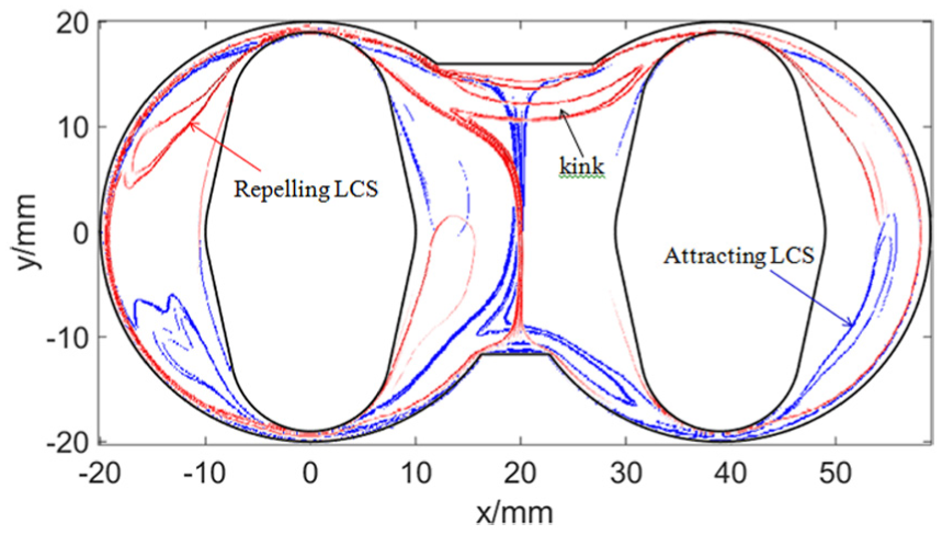
The repelling LCS (red) and attracting LCS (blue) redrawn from the FTLE maps in the two-winged rotor mixer with speed ratio of 3:2.
Heat transfer characteristics
When the speed ratio of 15:10 r/min and TW = 493 K are employed as boundary conditions, the temperature and the mass fraction distributions of resultant TiO2 and reactant Ti(OR)4 in the mixers with single-winged and two-winged rotors are illustrated in Figures 5 and 6, respectively. It is clear from Figure 5(a) and (b) that the temperature values near the rotor wings are higher than those near wall in the mixer. This is because the reactive fluid has great shear rates near the wings of rotors than the chamber. The temperature values are higher in the left half channel than right half channel due to the great shear rate with high the left rotor speed. Correspond, the high temperature fluid has big mass fraction of resultant (TiO2) due to great reactive rate, as shown in Figures 5(c) and 6(c). With the increasing of reactive time, the temperature rises and mass fraction of resultant for the reactive fluid increase, as shown in Figures 5(d) and 6(d). However, the mass fraction of resultant for the reactive fluid decreases with the increase of reactive time, as shown in Figure 5(e) and (f). In addition, comparison with Figures 5 and 6, it can be found that the reactive fluid has higher temperature and mass fraction of resultant in the mixer with two-winged rotors than those with single-winged rotors due to great shear rates.
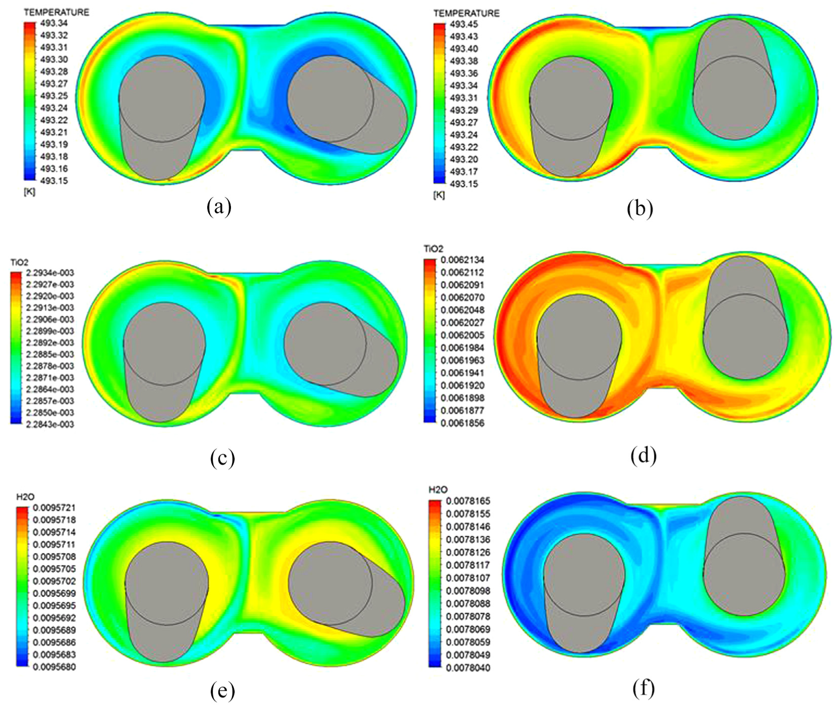
Temperature and TiO2 concentration distributions in the mixer with single-winged rotors (speed ratio of 15:10 r/min and TW = 493 K): (a) temperature distribution at t = 10 s; (b) temperature distribution at t = 30 s; (c) TiO2 concentration pattern at t = 10 s; (d) TiO2 concentration pattern at t = 30 s; (e) H2O concentration pattern at t = 10 s; and (f) H2O concentration pattern at t = 30 s.

Temperature and TiO2 concentration distributions in the mixer with two-winged rotors (speed ratio of 15:10 r/min and TW = 493 K): (a) temperature distribution at t = 10 s; (b) TiO2 concentration distribution at t = 10 s; (c) temperature distribution at t = 30 s; (d) TiO2 concentration distribution at t = 30 s; (e) H2O concentration distribution at t = 10 s; and (f) H2O concentration distribution at t = 30 s.
In order to better learn about the local temperature changes during the reactive process, three probe points in the mixer are selected, as shown in Figure 7. Meanwhile, Locations A and B locate in the gap between barrel and rotor wings of left and right channels in the mixers with single-winged and two-winged rotors, respectively. Location C locates in the center of the mixing region in the mixers.

Positions of three detecting points in the mixer.
The temperature changes of three probe points (see Figure 7) in the mixer with single-winged and two-winged rotors under the speed ratio of 15:10 r/min and TW = 493 K are shown in Figure 8. Initially, all temperature magnitudes in the mixers with single-winged and two-winged rotors increase with time until the thermal steady state is obtained at about 110 s. Meanwhile, Location C has higher temperature than Locations A and B due to great shear rate and high mixing efficiency in the mixing region. At the same time, it can be found from Figure 8 that the amplitudes and periods of temperature fluctuations in Location C during the steady state are larger than those in Locations A and B. This is due to the fact that the shear rate value and its changed frequency induced by rotor wings are higher in Location C than in Locations A and B. On the other hand, in the same local positions of the flow region, the reactive fluid in the mixer with two-winged rotors has higher temperature than that with single-winged rotors due to great shear rates. In addition, it can be observed from Figure 8 that the period of temperature change in the mixer with two-winged rotors is about 2 s and more two times than that with single-winged rotors due to great numbers of two-rotor wings.
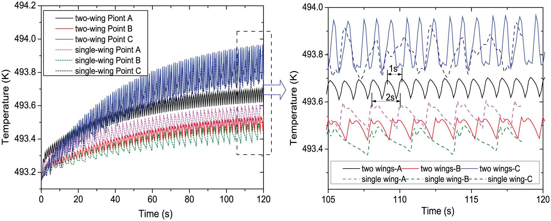
Temperature changes of three detecting points in the mixer with two types of rotors.
Relationship of transportation and heat transfer
Comparing with Figures 3, 5, and 6, it can be found that the higher temperature values mainly locate in the outer region, where fluid transport is better, and the lower temperature values mainly locate in the inner region, such as near the rotor wall due to the poor fluid transport in the mixer with two-winged rotors. At the same time, the fluid near the horseshoe map has also great temperature magnitude due to the high material exchange. Moreover, the temperature separatrix of left and right chambers is almost similar to the repelling LCS due to the underlying quasi-boundary of fluid transport. In addition, it is noted that Location C is near the degenerate homoclinic point, where there is better fluid transportation. Therefore, the fluid temperature magnitude in location C has great temperature (see Figure 8) due to the combination of fluid transportation and shear rate.
Effect of rotational rotor speed on the heat transfer
The rotor speed is an important factor to determine the output during operation conditions. The influences of rotor speeds and speed ratios on the average temperature distributions in the mixers with single-winged and two-winged rotors at TW = 493 K are shown in Figure 9(a) and (b), respectively. It is found from Figure 9(a) that the average temperatures in the mixers increase with increasing the rotational speeds due to the increasing shear rates. On the other hand, the fluid in the mixer with two-winged rotors has higher average temperature values of reactive fluid than that with single-winged rotors because of the relatively great overall shear rates and chaotic mixing strength. In Figure 9(b), it is obvious that with the increasing of the rotor speed ratios, the average temperatures in the mixers also increase. This is mainly because the chaotic mixing strengths in the mixers with single-winged and two-winged rotors increase due to the non-symmetric flow field induced by the asymmetrically rotational speed ratios.

Influences of rotor rotational speeds and speed ratios on the average temperature distributions with TW = 493 K: (a) rotational speeds and (b) speed ratios.
The effects of rotational speeds on the viscous dissipation and viscous heating in the mixer with single-winged rotors at TW = 493 K are illustrated in Figures 10 and 11, respectively. Generally, the local shear rate determines the viscous heating the mixers. From Figure 10, it is obvious that the viscous dissipation increases significantly with increasing of rotor speeds and the numbers of rotor wings due to great local shear rate of reactive fluid. In addition, the viscous dissipation fluctuations in the mixer with single-winged rotors at speed of 30:20 r/min are larger than those at 15:10 and 9:6 r/min, as shown in Figure 10. This is because that the reactive fluid in the mixer with two-winged rotors has faster change of shear rate than that with single-winged rotor propelled by the rotor wings.

Effects of rotational speeds on the viscous dissipation at Location A with TW = 493 K.

Effects of rotational speeds on the viscous heating at Location A with TW = 493 K.
As shown in Figure 11, it is clear that the amplitude of viscous heat generation increases significantly with increasing of the rotor speeds. This can also be identified from temperature pattern as illustrated in Figure 8. However, when the rotational speeds in the mixers are same, the amplitudes of viscous heat generation in location A of the mixers with single-winged and two-winged rotors are almost same. But the viscous heating generation of single-winged rotor has smaller period of fluctuation than that of two-winged rotors. Therefore, the viscous dissipation increases significantly with increasing of the numbers of rotor wings.
Torque refers to the hindering force melt, when polymer resins or compounds are plasticized and mixed with rotation of rotors. Figure 12 shows the effects of rotational speeds on the torques of right rotor in the mixers with two types of rotors at TW = 493 K. In Figure 12, the torques of right rotor increases with the increasing of the rotor speeds, which lead to both increase of local shear rates and viscous dissipation. In addition, the torques of right rotor also increase with the increase of the number of rotor wings. This corresponds to the rules of viscous dissipation in the mixers.

Effects of rotational speeds on the torques of right rotor with TW = 493 K.
Effect of initial barrel temperature on the heat transfer
Temperature increases are mainly due to the viscous dissipation and heat transfer from the barrel. Meanwhile, the barrel temperature is an important factor to control the temperature change of the reactive system. Figure 13 shows the effects of initial barrel temperatures on the average temperature in the mixers with single- and two-winged rotors. It is found that the average temperature in the mixers increases rapidly with increasing the initial barrel temperatures due to the decreasing of reactive fluid viscosity caused by high temperatures. On the other hand, the mixer with two-winged rotors has higher average temperature value of reactive fluid than that with single-winged rotors, because the mixer with two-winged rotors has relatively great overall shear rate. In addition, it can be found from Figure 13 that the temperature rise in the mixers decreases with the increasing of barrel temperatures. At the same time, the temperature differences in the mixers between the single-winged and two-winged rotors also decrease with the increasing of barrel temperatures likely due to the better mixing efficiency.

Effects of initial barrel temperatures on the average temperature in the mixer.
Figure 14 gives out the influences of initial barrel temperatures on the viscous heating at Location A in the mixer with single-winged rotors at speed ratios of 15:10 r/min. It is clear from Figure 14 that the viscous heating at Location A decreases with increasing the initial barrel temperatures. This is due to the fact that the viscosity of reactive fluid decreases with the increasing of the initial barrel temperatures. It also implies that the temperature rises caused by viscous heating are lower with low initial barrel temperature. Moreover, the influences of initial barrel temperatures on the viscous dissipations at Location A of the mixers are shown in Figure 15. As shown in this figure, it can be found that the viscous dissipation decreases with the increasing of the initial barrel temperatures. The viscous dissipation leads to increase the temperature throughout the mixer, as shown in Figure 13. Furthermore, the mixer with single-winged rotors has bigger viscous dissipation than that with two-winged rotors due to great local shear rate caused by much rotor wings at the same initial barrel temperature.

Influences of initial barrel temperatures on the viscous heating at Location A.

Influences of initial barrel temperatures on the viscous dissipations.
The effect of initial barrel temperatures on the torque of right rotor in the mixes at Location A with speed ratio of 15:10 r/min is shown in Figure 16. It can be seen from Figure 16 that an increase initial barrel temperature results in a lower torque of right rotor. This is because when the barrel temperature is higher, a viscosity of reactive fluid is lower. Therefore, the mixing efficiency and local shear rate are higher, leading to a lower torques of two rotors. From torques distributions of rotors in Figures 13 and 16, it is noted that the torques changes of single-winged rotors are greater than those of two-winged rotors. This is because the frequency of propelled effects by the rotor wings with two-winged rotors is faster than those with single-winged rotors.

Effects of initial barrel temperatures on the torques of right rotor.
Conclusion
Different from the co-rotating rotor mixer, the repelling and attracting LCSs of counter-rotating rotor mixer only has the degenerate homoclinic points, resulting in the decrease of fluid folding action. The critical mixing state can be found in the mixer with the rotor speed ratio of 3:3, where there is almost nothing material exchange in the left and right chambers. With the increase of the rotor speed ratios, such as rotor speed ratios of 3:2 and 3:1, the critical mixing condition is break down and the material exchanges in the left and right chambers increase.
The reactive fluid in the left half channel has greater temperature value than that in the right half channel due to great shear rates and better fluid transport. Also, the mixer with two-winged rotors has higher average temperature value of reactive fluid than that with single-winged rotors.
Those parameters, such as average temperature, viscous dissipation, viscous heat generation, and torque of rotor, in the two types of mixers all increase with increasing the rotational speeds. Moreover, above parameters in two-winged rotor mixer are bigger than those in single-winged rotor mixer. The sensitivity of conversion rate for this sol–gel reaction is sensitive to the initial barrel temperature in the internal mixers.
The temperature distribution depends on both shear rate and fluid transportation in the internal mixer. The fluid in the outer region with better fluid transportation has higher temperature value than that in inner region with relatively poor fluid transport. Moreover, the fluid near the horseshoe map has also great temperature magnitude due to the high material exchange.
From the viewpoint of fluid transportation and temperature characteristics, the internal mixer with two-winged rotors increases in comparison to the single-winged rotors, but not significantly. Future work will devise a novel rotor mixer, such as adding the grooves on rotor wings, to significantly increase the mixing and heat transfer efficiency.
Footnotes
Handling Editor: Ishak Hashim
Declaration of conflicting interests
The author(s) declared no potential conflicts of interest with respect to the research, authorship, and/or publication of this article.
Funding
The author(s) disclosed receipt of the following financial support for the research, authorship, and/or publication of this article: This research project was funded by National Natural Science Foundation of China (grant no. 51473073 and 50903042), Program for Liaoning Excellent Talents in University (grant no. LR2016022), and Natural Science Foundation of Liaoning Province (grant no. 2015020142).