
Abstract
A dynamic model of serial robots with multiple clearance joints is developed. The contact phenomenon in the clearance joint is modeled by a continuous dissipative Hertz contact theory, and the friction force is calculated based on the modified Coulomb’s friction law. A neural network method is employed to predict the dynamic response, which avoids the problem in solving the differential algebraic equations. An approximate internal model-based neural control method is proposed to control the undesired effects arising from the joint clearances. The validity of the proposed method is verified by simulation results.
Introduction
Precision robotic manipulators are highly demanded in many areas, for example, industry, medicine, and aerospace. The precise modeling of large-scale manipulators remains as a challenge, particularly in some complex working circumstances, such as serial manipulators with open-loop topology. As the core component of manipulator, the joint plays a crucial role in power transmission, mechanical connection, and state measurement tasks.1–5 Due to manufacturing error and the requirements in assembly and working processes, clearance in the articulating joint is inevitable.6–8 The clearance introduces nonlinearity to the mechanical arm system, which is the main factor that influences the positioning precision and motion smooth.9–11 In addition, the errors are accumulated and amplified in the serial manipulator, leading to collision in the joint and vibration of the system, consequently a considerable tip positioning inaccuracy.12–14 Generally, the manipulator joint is simplified, and the nonlinear factors are neglected in the dynamic modeling, resulting in an irrational and unpredictable manipulator response. Therefore, it is essential to establish an accurate dynamic model of clearance joint for the design, characteristic analysis, and response prediction of large-scale serial manipulators.
Various models have been reported to study the effects of joint clearance on dynamic behavior of different mechanisms. Binaud et al. 15 have compared the 3-PPR planar parallel manipulators with respect to their workspace size and kinematic sensitivity to joint clearances. Two non-convexquad radically constrained quadratic programs were formulated disorder to find the maximum reference point position error and the maximum or iotation error of the moving platform for given joint clearances. Khemili and Romdhane 16 have investigated the dynamic behavior of a planar flexible slider–crank mechanism with joint clearance. Simulation and experimental tests were carried out for this goal. Flores and colleagues,11,17–27 Erkaya and colleagues,28–30 Schwab et al. 31 have investigated the effects of joint clearances on kinematics and dynamics of planar and spatial mechanisms with rigid and elastic links. Bauchau and Rodriguez 32 have investigated the modeling of joints with clearance within the framework of finite element-based dynamic analysis of nonlinear, flexible multibody systems. Liu et al. 33 have presented an approximate model to describe the properties of the contact in the cylindrical joint with clearances. Venanzi and Parenti-Castelli 34 have presented a new method based on the principle of virtual work for studying the kinematic influence of clearance affected pairs on the position and orientation of the links of spatial mechanisms. Altuzarra et al. 35 have presented a methodology for analyzing the location of the discontinuities in a 5R parallel mechanism with joint clearance.
Typically, current dynamic models of clearance joint can be classified into three main categories. The continuous contact model20,36,37 assumes that the pairing elements at work always keep contact with each other. The two-mode model holds that the pairing elements exist two states,38,39 that is, contact and free movement. The three-state model 10 exists three phases, the contact, freedom, and collision contact. The three-state model is the most accurate one to reflect the actual motion states of mechanisms with clearance joints. However, it is very difficult to solve the nonlinear differential equations for these models.
Dynamic modeling results can be used to control the nonlinear factors and then to improve the system precision. There are a lot of studies on dynamic modeling, but very few reported the dynamic control of serial manipulator with clearance joint. Current methods on nonlinear dynamic control of mechanism with clearance joint include design optimization, lubrication, adding weight, and inserting spring between the links, and so on. Erkaya and Uzmay28,29 reported that the effects of joint clearances on mechanisms can be decreased to some degree using both link flexibility and balance. Erkaya et al.40,41 also studied dynamic behavior of a four-bar mechanism with clearance joints. A neural network (NN)—genetic algorithm approach was employed to model the characteristics of joint clearance and to reduce the vibration effects arising from joint clearance. Lai et al. 42 proposed a model for a path-generating mechanism by combining the multi-rigid-body system dynamics theory and the joint clearance contact theory. The influence of various noises resulting from the structure (clearance, dimensional, and assembling errors) and dynamic (friction, velocity, and loading) factors is considered in this model. Yaqubi et al. 43 studied the dynamical behaviors and control of planar crank–slider mechanism considering the effects of link flexibility and joint clearance. Overall, these researches pointed out the feasibility to reduce the negative effects of clearance joint on the dynamic behavior through modeling. However, these models cannot be directly used to study the system performance and to design the controller because it is difficult to solve the strong nonlinear rigid equation.
Due to the good approximation performance, NN has attracted much attention in the modeling and controlling of uncertain nonlinear systems. Here, a dynamic model of serial robot with multiple clearance joints was developed. The contact phenomenon in the joint was described by a continuous dissipative Hertz contact model, and the modified Coulomb’s friction law was used to calculate the friction force. Then, an approximate internal model-based neural control method (AIMNCM) was proposed to identify and model the serial mechanism. The multi-layer NN control method was demonstrated to reduce the undesired effects of joint clearances on the dynamic performance of serial robot, which is advantage of overcoming the difficulties in solving the differential algebraic equations (DAEs).
Modeling of the serial robots with multiple clearance joints
Figure 1 shows the structure of a typical serial robot, which has k rigid links and multiple clearance revolute joints. The global coordinate system (OXY) origin is constructed on the geometric center of the first bearing fixed on the ground. The centers (O) and radii (R) of the ith bearing and journal are Oi1, Oi2, and Ri1, Ri2, respectively. The ith link center mass is Si, and its length and mass are Li and mi, respectively. The centroid distance between the ith link and the journal is LSi. The moment of inertia associated with the rotation is Ji. The torque acting on the ith link is Ti. The angle, angular velocity, and angular acceleration are

The structure of the serial robot with multiple clearance joints.
As shown in Figure 2, the eccentricity of the bearing in the ith link joint (ei) is defined as
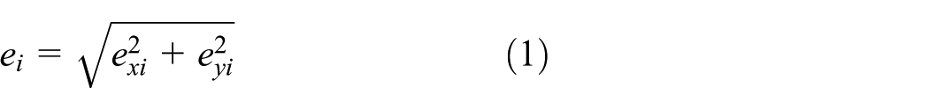
where exi and eyi are the components on the X and Y axes of the eccentric vectors.

Revolute clearance joint.
The rotation angle of the coordinate system (
The penetration depths (δi) due to contact between the bearing and journal are calculated as

where the clearance size (ci) is the radius difference between the ith journal and bearing.

when,
Kinematic analysis
The kinematic model of the serial robots with clearance joints was established as follows. Specifically, the displacement, velocity, and acceleration equations of the centroid (Si) of the ith link are expressed as

Similarly, the kinematic equations for the end-effector of manipulator are expressed as

Dynamic model
The dynamic model was derived based on the Newton–Euler equation. From the Newton’s second law, the forces acting on the kth link (Fk) and end-effector (FB) are related and can be calculated as

According to the Euler equation, the torque acting on the kth link can be derived as

Similarly, the contact force and torque on the jth link are expressed as follows

where,

where

where,

Contact–impact force models
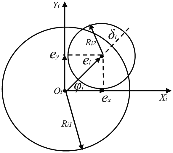
In order to compute the dynamic equations of real mechanisms having clearance joints, a step function
As shown in Figure 3, the x and y components of the tangential and normal forces projection on each axis can be obtained by equation (12)

where, Fit and Fin are tangential friction force and normal impact force, respectively.
Contact-impact forces defined at the contact point.
The contact force is studied using a continuous contact force model,44,45 considering the damping hysteretic factor to account for the energy dissipation, which is expressed as
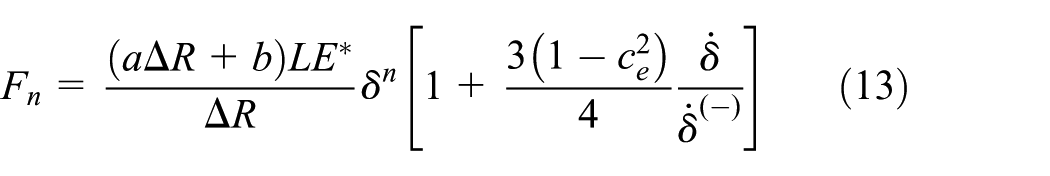
where
The constant Y in equation (13) is given by

where

The friction force acted on the sliding bodies is opposite to the sliding velocity and is tangential to the surface of contact. It can be modeled as 46

where vt is the relative tangential velocity and cf is the friction coefficient. cd is the dynamic correction coefficient and given by

where v0 and v1 are given tolerances for the tangential velocity.
Application of the approximate internal model-based neural control
NN-based system identification
The dynamic mathematical model of the serial robots with multiple clearance joints is expressed in the differential algebraic equation (10) in section “Dynamic model.” The essence of NN identification is to select a suitable NN structure to approximate the actual dynamic system. The specific process is to measure the output of the research object under the given input response; or the actual operation of the input and output data is obtained using a certain algorithm to train the NN. Therefore, the network connection threshold and weight can be adjusted to obtain the minimum required error criterion. And then the nonlinear mapping relation implied in the input and output data of the system is summarized, and the description of the dynamic characteristics of the system is realized. The specific process of NN identification is shown in Figure 4.

The NN identification process.
Set the actual output of the system as y, the output of the NN model is

where
The mathematical model (equation (10)) of the serial robots with multiple clearance joints can be expressed as the following compact input and output form

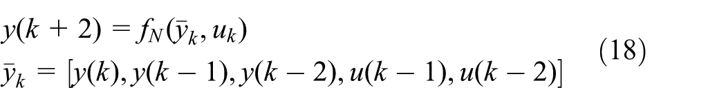
Discrete equation (17), then the system model corresponding to equation (11) is solved using the NN nonlinear identification method, which can be expressed as follows
Approximate NN internal model control
The NN approximation model of the serial robots with multiple clearance joints (equation (19)) can be obtained by Taylor expanding equation (18) about

where

The system controller incremental

where
Due to the error in simplifying the model construction and the nonlinear effect of joint clearance, there are obvious uncertainties in the serial robot system with multiple clearance joints. Therefore, the uncertainties cannot be neglected in designing the internal controller of the system NN. The structure of NN approximate internal model control is shown in Figure 5.
The structure of NN approximate internal model control.
The function of setpoint filter in Figure 5 is to provide a stable motion reference trajectory for the system. Assuming that the reference trajectory is

The role of robust filter

From equations (19)–(22), the NN approximation model can be rewritten as follows

Equation (23) shows that the uncertain factors of errors and disturbances in construction of the system model can be compensated by proper selection of the appropriate filter
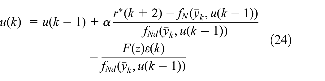
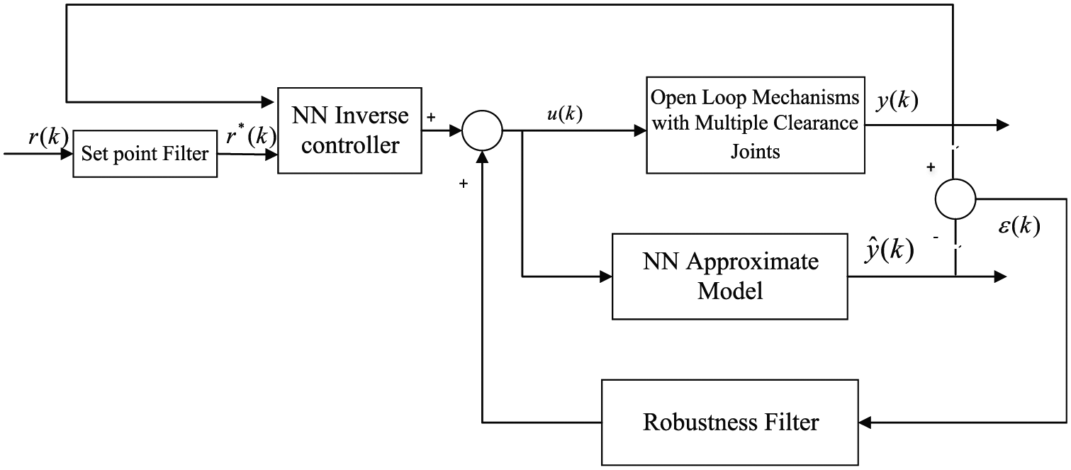
The structure of the NN approximation internal model controller of the serial robots system with clearance joint given by equation (24) is shown in Figure 6.

Approximate internal model-based neural control to serial robots with multiple clearance joints.
Results and discussion
High precision is very important for the functioning of the system. Here, a serial robot with 4 degrees of freedom is designed to demonstrate the dynamic and controlling models. The end-effector of the serial robot is designed to bear a load of 2.0 kg. The serial robot system structure (Figure 7) is simplified to reduce the weight and for ease of manufacturing. The bodies of the serial robot are assumed as rigid.

A typical example of the serial robot.
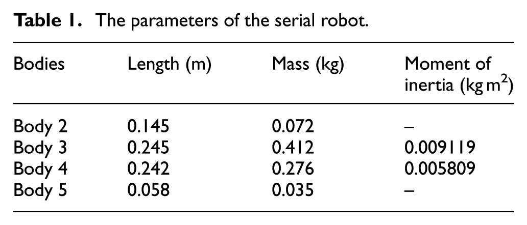
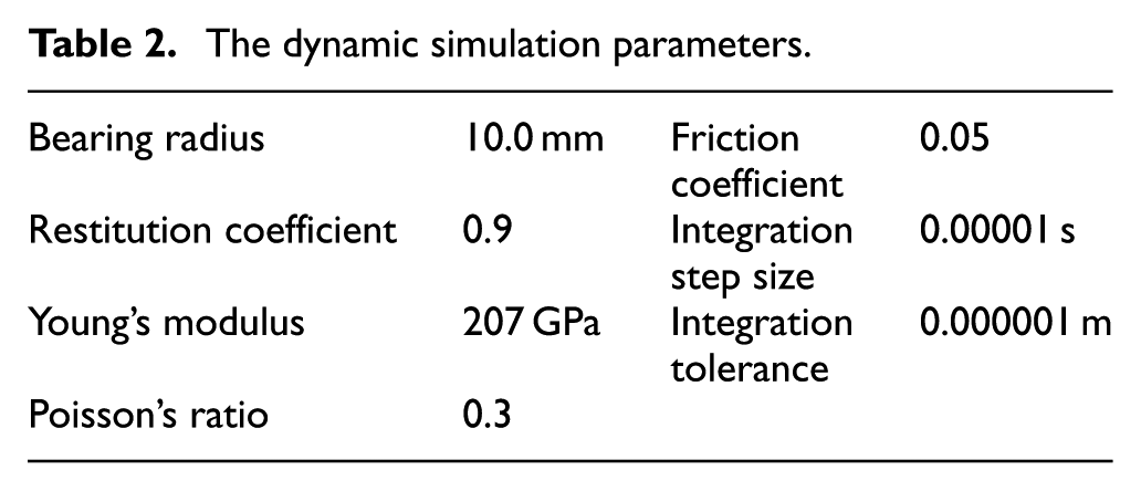
The parameters of the serial robot and the dynamic simulation parameters are listed in Tables 1 and 2, respectively. To discuss the dynamic influence of the serial robots with clearance joints, it is assumed that joints 2 and 3 can move, the other joints are fixed. Each radial clearance value is considered as 0.03 mm. The centers of the journal and the bearing are assumed to coincide before the manipulator motion started at t = 0. Based on the system model in equation (10), set the system input as: the driving torque applied on joint 2 is 4sin(2πt) N m, and the torque applied on joint 3 is 2sin(2πt) N m.
The parameters of the serial robot.
The dynamic simulation parameters.
There are few reports on experiment studies of dynamic behavior of complex multibody system with clearance joints because it is difficult to do so.28,47–51 Therefore, the theoretical modeling results are commonly verified by dynamic simulation. 52 MSC.ADAMS, a commercially available package, was used to validate the theoretical model of the serial robot manipulator dynamic behavior, with the same geometric and inertial parameters. As shown in Figure 8, the simulated result is almost like the theoretical result, except there is a large variation in the acceleration response. This may be caused by the energy dissipation in the contact force model was not studied in the simulation. In addition, MSC.ADAMS does not correct the error in solving the traditional DAE equations of multibody system dynamics.

Comparison between the numerical modeled and (a) ADAMS simulated displacement, (b) velocity, and (c) acceleration responses of the revolute joint with clearance.
Figure 9 shows the effect of joint clearance on the system dynamic behaviors, including the displacement (Figure 9(a)), velocity (Figure 9(c)), and acceleration (Figure 9(e)). Compared the serial robot without clearance joint, the mechanism with clearance joint has obvious effect on the dynamic behavior of the end-effector, which clearly displayed in the errors of its center of mass in the Y-direction (Figure 9(b), (d), and (f)). In particularly, the error increases from a few tenths of the displacement (Figure 9(b)), to the maximum of 1 m/s in the velocity, and to the two orders of magnitude in the acceleration. These errors result in the vibration of the mechanism with a high amplitude, and hence the movement accuracy and stability. This acceleration characteristic can also be considered as a source of shaking, vibration, and noise in mechanism dynamics. The deviation from the ideal case may be caused by the external loadings acted on the system, including the gravitational force of bodies and the impact force in the clearance joint. The effect of impact force in the clearance joint is reflected by the high peaks in the system (Figure 9(f)). These abnormal changes make the dynamic performance of the mechanism worse. These signals are used as the output samples obtained using the NN identification of the serial robot with multiple clearance joints.

The output signals (a, c, e) and their error (b, d, f) obtained by using the NN identification of the serial robot with multiple clearance joints.
The three-layer dynamic BP NN with two hidden layers is employed to identify the serial robot with multiple clearance joints. The outputs include end-effector displacement, velocity, and acceleration. Empirically, the number of nodes in the hidden layer of the NN is selected from 5 to 30. The number of hidden layer nodes in the first and second layers is selected as 13 and 14, respectively. The other parameters in the NN model are set as follows: the NN structure is
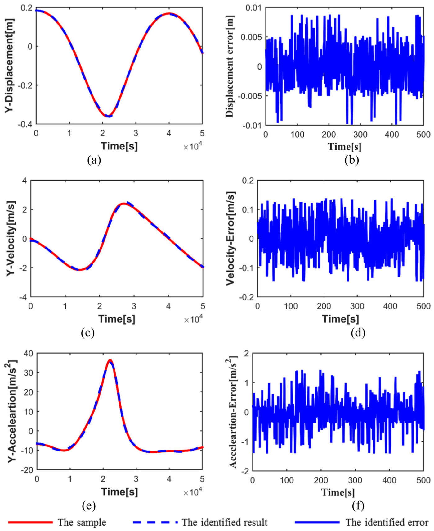
The dynamic response (a, c, e) and the identified error (b, d, f) of the serial robot with clearance by the identified NN model.
Figure 11 shows the dynamic response of the serial robot with joint clearance, which can be well controlled by the NN internal model controller. Comparing the dynamic tracking errors of the serial robot having joint clearance without (Figure 9(b), (d), and (f)) and with controller (Figure 11(b), (d), and (f)), the maximum absolute errors of displacement and velocity are 2.4 × 10⁻⁴ and 7.7 × 10⁻³, respectively, and the error of acceleration is reduced by 10 times with the controller. These results further demonstrate the effectiveness of the NN internal model controller. It can be concluded that the proposed control method not only combines the advantages of both nonlinear internal model-based neural control and inverse control but also eliminates some disadvantages, which avoids the problem in solving the DAEs. The control method is very simple which needs only one identified NN model for model approximation.

Dynamic responses (a, c, e) and dynamic tracking errors (b, d, f) of the serial robot with joint clearance controlled by NN internal model controller.
Conclusion
A dynamic model of serial robots with multiple clearance joints was developed. The contact phenomenon in the clearance joint was modeled by a continuous dissipative Hertz contact law, and the friction force was calculated based on the modified Coulomb’s friction theory. An NN method was provided to predict and estimate the dynamic response of the serial robot with multiple clearance joints, which avoids the problem in solving the DAEs. An approximate internal model-based neural control method (AIMNCM) was proposed to study the dynamic behavior and to precisely control the serial robots with multiple clearance joints. The control method is very simple with only one identified NN model for model approximation. The results show the effectiveness of predicting and estimating the dynamic response of the mechanical system with multiple clearance joints and the feasibility of reducing the undesired effects arising from joint clearance using the NN control method.
Footnotes
Handling Editor: Fakher Chaari
Declaration of conflicting interests
The author(s) declared no potential conflicts of interest with respect to the research, authorship, and/or publication of this article.
Funding
The author(s) disclosed receipt of the following financial support for the research, authorship, and/or publication of this article: This work was supported by the National Natural Science Foundation of China (grant numbers U1501247, U1609206, 91223201), Natural Science Foundation of Guangdong Province (grant numbers S2013030013355, 2015A030310239), and Foundation of Guangzhou (grant numbers 2019KC221).