
Abstract
The thermal behavior of the standard planetary roller screw mechanism needs to be investigated since the large amount of heat generated by the friction torque on multiple contact points during the transmission process. In this article, a simplified transmission system model of standard planetary roller screw mechanism is first established for the finite element analysis. Second, the friction torque of standard planetary roller screw mechanism is calculated and the boundary conditions of thermal analysis are deduced. Then, the transient thermal analysis of the standard planetary roller screw mechanism based on finite element method is conducted by considering the moving heat source and thus temperature field distribution at any time and the temperature rise curve at different positions of the standard planetary roller screw mechanism can be obtained. Finally, the correlation between the experimental data and the calculated values confirms the validity of the proposed thermal model for the transient thermal analysis.
Keywords
Introduction
With the rapid development of more/all electric aircraft and industry equipment, the standard planetary roller screw mechanism (SPRSM) has attracted much attention due to its high thrust, high precision, and long life.1,2 Compared with the ball screw mechanism (BSM), the SPRSM provides more contact points than BSM with a comparable size. For an aircraft, the planetary roller screw mechanism (PRSM) is a key component used in electro-mechanical actuators (EMAs) for controlling the ailerons, rudder, and elevator. 3 However, the friction in the SPRSM during the longtime movement at high speed cannot be ignored since it leads to the temperature rise and actuation accuracy degradation. If excessive heat generation and insufficient heat transfer occur in the SPRSM, the service life of SPRSM can be affected and the SPRSM even may fail. Therefore, it is important to establish a thermal model to understand the thermal behavior of SPRSM system. 4
Some fundamental studies have been conducted to support the engineering application of SPRSM. Xu et al. 5 established a finite element thermal model for the temperature rise variation rule of BSM. Bossmanns and JF Tu 6 developed a thermal model based on finite difference method to characterize the power distribution and heat transfer. Zheng et al. 7 established a complete thermal model by finite element method and studied the temperature history of high-speed press system. Ma et al. 8 established friction torque models of roller screw considering the grease effect, elastic lag, and sliding friction in the contact area. Aurégan et al. 9 proposed a calculation method based on elastic theory and developed an instrument with a sliding component to simulate the contact between the roller and the screw. Fu et al. 10 derived the meshing equation on the interface of roller and nut, and calculated the clearance and contact position of thread meshing surface in PRSM. Wei et al. 11 derived the mathematical models of different screw cross-section profiles, and the mixing properties of several typical screw elements with end section are analyzed. Jones et al. 12 established the dynamic equation of PRSM and found that the slip velocity of PRSM is related to the contact angle of the screw and nut. Jones and Velinsky 13 established the contact surface between nut and roller and screw, analyzed the position of contact point and contact radius, and derived the principal curvature radius at the contact points of PRSM and the angle between principal axes. Abevi et al. 14 studied the static characteristics, axial stiffness, and load distribution of planetary roller screw (PRS), and the global and local deformation of PRS are obtained by numerical analysis. Zhang and Zhao 15 simulated the forming process of shaft parts with thread using finite element numerical simulation method. Using the finite element method, Min and Jiang 16 established the thermal model of the ball screw and obtained the heat boundary conditions including the convection coefficient and the heat flux using Fourier’s law. The temperature rise of feed drive system is mainly considered, the heat produced by ball screw, guide rail friction, and bearing. The simulated data are consistent with the data measured by infrared thermometer, which verifies the rationality of the established model. Xu et al. 17 established the thermal model of ball screw using finite element method (FEM) and modified lumped capacitance method (MLCM), respectively, which is used to analyze temperature distribution, air cooling performance, and thermal deformation. Su et al. 18 calculated the thermal contact resistance (TCR) by finite element fractal method and studied the contact pressure distribution of the machine tool. Ma et al. 19 found that thermal contact conductance increases with the increase in the contact area and contact load, which is helpful for study of heat transfer between contact surfaces. Liu et al. 20 combined the thermal model with the finite element simulation and used the analytical simulation method to model the angular thermal error of spindle. Li et al. 21 calculated the convection coefficient and the thermal critical point of a feed drive system.
In recent years, many new discoveries have been made in the study of thermal analysis. Cui et al.22,23 considered the variance of temperature gradient in the smooth region and established a stable smooth finite element method based on triangular and tetrahedral elements. They used the radial point interpolation method based on triangular elements or tetrahedral elements to solve the three-dimensional (3D) heat transfer problems. Yang and Cui 24 proposed a random field based on node integral domain to solve the steady-state heat transfer problem of thermal conductivity varying with material parameters. Moradi-Dastjerdi and Payganeh 25 approximated the heat transfer equation with the least square shape function. Draganis 26 proposed the calculation framework of transient thermal–mechanical coupling and rolling friction contact analysis based on the description of arbitrary Lagrangian–Euler kinematics. Rizk et al. 27 studied the heat conduction and natural convection inside the battery and determined the necessary parameters through experiments.
However, there is limited research on the thermal modeling of the SPRSM. Previous studies are beneficial to the establishment of the temperature field calculation method of SPRSM, but the influence of boundary conditions and lubricating oil viscosity on the heat transfer process has not been fully considered. In this study, the heat generation on the nut and the screw is calculated based on the friction torque analysis of the SPRSM. The heat flux is loaded on the simplified 3D model, and the temperature change curves are obtained using finite element method. At the same time, the SPRSM is operated experimentally, and the temperature rise curve is recorded. The proposed model is validated by comparing the simulation results with the experimental ones.
Mechanical structure
The 3D model of the actual SPRSM is the basis for the thermal analysis. The geometric size of the model is the same as the actual SPRSM specimen, so that the thermal performance of the SPRSM can be correctly reflected in the analysis and calculation. The SPRSM is composed of the screw, nut, roller, ring gear, and retainer, as shown in Figure 1. The structural parameters of the SPRSM are provided in Table 1. The thread angle of the screw and nut is 90°, which benefits to obtain the best load-carrying capacity. The axial section of the roller thread is a central arc on the axis, which can be replaced by effective ball contacts in this study. When the screw is driven by a motor, the roller transmits the power to the nut for resisting the external load, and the roller and nut move straight along the axis of the screw. The components of the SPRSM are modeled by SolidWorks software.

3D model of SPRSM.
Parameters of the SPRSM.

SPRSM: standard planetary roller screw mechanism.
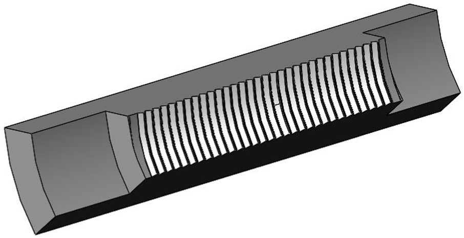
In order to facilitate the mesh generation of the model, the conversion of the SPRSM computer-aided design (CAD) model to the computer-aided engineering (CAE) model ignores some small features, such as chamfer, roundness, receding groove, bolt holes at the end of the screw, and the threads used to connect with locking nuts. These fine structures are designed to facilitate the processing and assembly of the SPRSM. They have little effect on the analysis of temperature field on the screw and nut. It is considered that the structure of the studied object is circularly symmetric and that there are 10 rollers with symmetrical circumferential distribution, so the screw and the nut can be cut into the original 1/10 for simulation calculation. The simplified nut model is shown in Figure 2, and the screw model is shown in Figure 3.
Simplified nut model.

Simplified screw model.
Modeling
Element type
In the temperature field, SOLID90 and SOLID87 are often used to divide the mesh, which are listed in Table 2. However, in order to improve the accuracy of the calculation, only the SOLID90 (hexahedron element) is used in the ANSYS analysis. The two types of three-dimensional solid elements are shown in Table 2.
Three-dimensional entity unit.

Material properties
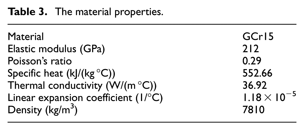
In this article, the ambient temperature is 25°C, and the material properties can be simplified to constants. In the thermal analysis of the SPRSM, the following parameters should be determined in the temperature field simulation: thermal conductivity λ, density ρ, specific heat c, elastic modulus E, Poisson’s ratio μ, and thermal expansion coefficient α. The material of the nut, roller, and screw is GCr15, and their related thermo-physical properties are shown in Table 3.
The material properties.
Mesh generation
The SPRSM components are meshed using ANSYS Workbench. The thread teeth of the nut and the screw are cut out and meshed by a sweeping mesh method, while the other parts adopt the multi-zone division mesh method. Thus, these mesh methods result in all hexahedral elements. When dividing the mesh, the meshes in the contact part of the roller with the screw and nut are denser than those in untouched areas. The nut has 54,076 elements and 241,811 nodes, and the screw has 70,004 elements and 324,562 nodes. The mesh result is shown in Figure 4.

Mesh and boundary conditions: (a) nut and (b) screw.
In the working process of SPRSM, only the friction heat generated by the roller and the nut, the friction heat generated by the roller and the screw, and the convection of the SPRSM by the outside air are considered. Heat radiation is neglected since the temperature rise cannot be too high. The heat generation HSPRSM (heat produced in unit time) of the SPRSM is first calculated and heat flux fn and fs is directly loaded on the meshed model.
Thermal boundary condition
In the simulation process, the starting position of the nut is shown in Figure 4. The width of the moving heat source is 60 mm and the straight line stroke of the nut is 80 mm. The heat generated by the nut-roller interfaces is distributed in the contact area between the nut and the roller, which is presented as fn; since the nut moves in a straight line along the screw, a moving thermal load is simulated on the screw. The heat produced by the screw–roller interfaces is distributed in the contact position between the screw and the roller, denoted as fs in Figure 4. Besides, the thermal convection is applied to the air contact area, the thermal convection of the screw presented as hs, and the thermal convection of the nut presented as hn and hns. The three spot locations are shown in Figure 4, which are points #1, #2, and #3.
Friction torque and heat generation
The friction heat of SPRSM caused by grease effect, elastic lag, and sliding friction of roller under axial load is primarily considered in this article. 28
Load distribution
The following expressions of load distribution can be shown from Jin et al. 29

where the axial force is expressed as F;
Friction torque generated by elastic lag
As can be seen from Figure 5, the contact among the roller and the screw/nut is assumed to be a surface contact during the operation of the SPRSM. The normal cross section of contact is an ellipse, one side of the roller is in contact with the screw and the opposite side is in contact with the nut. Thus, the friction heat between the roller and the screw/nut is very necessary to be considered.
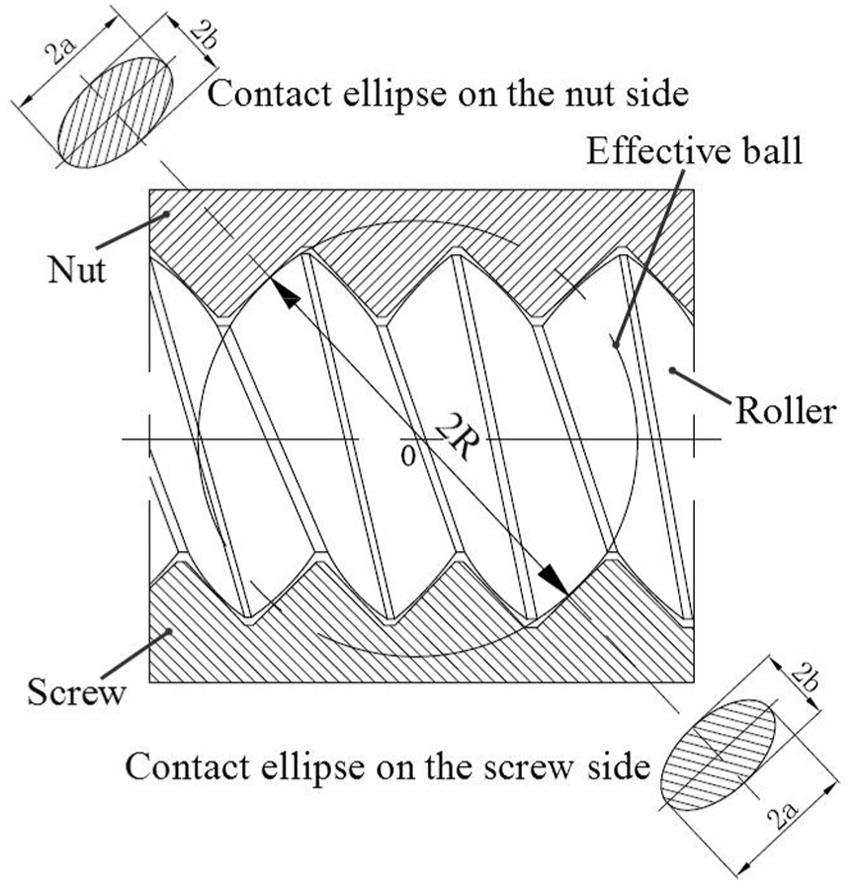
Contact ellipse and effective ball.
According to Hertzian contact theory, while the roller moves forward the unit distance along the short axis of the elliptical contact region, the work done by the contact stress can be expressed as follows

where
Due to the phenomenon of elastic lag occurring in the actual operation of SPRSM and the loss of conduction energy, the rolling friction torque can be stated as


where γ is the coefficient of energy loss and

The heat of SPRSM caused by elastic lag is evenly distributed across roller, nut, and screw. The friction torque due to elastic lag can be expressed as

where
Friction torque generated by the sliding friction
According to the force distribution and contact region distribution on the roller thread, the sliding friction torque in the differential regions can be obtained. The sliding load is distributed in the center of the contact ellipse region, so the friction torque generated for each roller on the nut and the screw is the same.
The axial sliding friction torque of screw is calculated by integrating from
The same for nut

where
Friction torque generated by grease
Under EMA condition, grease should be applied to the contact part of roller, screw, and nut. The friction force under lubrication can be represented by the following formula

where


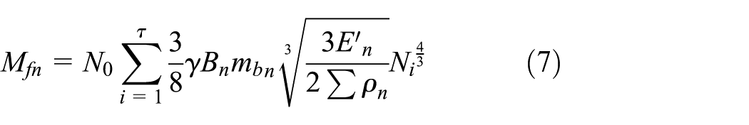
For the friction torque of all contact parts, assuming that there are
Thus, all the friction torque generated by the roller–screw interface and the roller–nut interface is


Finally, the total friction torque of SPRSM is

Heat generation of SPRSM
The SPRSM studied in this article can produce a lot of heat in the actual operation, which is mainly caused by the friction torque among the roller, screw, and nut. The heat generated by SPRSM can be expressed in the following form

where

where fn is the heat flux of the nut, and fs is the heat flux of the screw. Sn is the area of roll surface of all thread of nut and Ss is the area of roll surface of thread in stroke section of screw. A quarter of the heat produced by the friction of the SPRSM is transmitted through the roller surface to the screw axis, one-fourth heat to the nut side.
Convection coefficient
The outer surfaces of the screw and nut are in contact with air and heat exchange occurs. 30 According to the Nusselt criterion, the formula of convection coefficient h is as follows 31
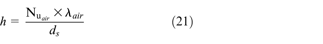
where λair is the heat conduction coefficient of fluid, and


where Re is Reynolds number,
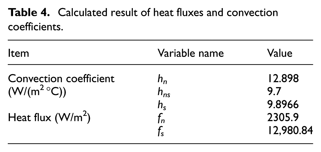
Calculated result of heat fluxes and convection coefficients.
Thermal analysis of SPRSM
In the finite element analysis of the temperature field of the SPRSM under given working conditions, the assumptions are as follows:
The convective heat transfer coefficient in different parts of the SPRSM is constant.
The ambient temperature of the SPRSM is constant and the ambient temperature is 25°C.
The nut reciprocates along the screw and corresponds to the displacement on the screw.
The thermal load of two parts is analyzed separately. The thermal load includes heat flow, heat flux, heat generation, and so on. In this article, the heat flux is used as the thermal load, and the heat flux is obtained by formulae (19) and (20). For the screw, heat is generated between the contact area of screw and roller, assuming that half of the heat is passed into the screw, that is the heat flux fs, and because the roller moves in an axial direction relative to the screw, using the moving heat flux as a thermal load on the screw; for nut, heat is generated between the contact area of nut and roller, assuming that half of the heat is passed into the nut, that is the heat flux fn.
Thermal analysis of nut
The transient thermal analysis of SPRSM is carried out using ANSYS Workbench software. The transient temperature field analysis is mainly used to analyze and calculate the temperature field of the SPRSM changing with time.
As can be seen from Figure 6, the maximum and minimum temperatures of the nut increase with the increase in the time, and the maximum temperature is 56.91°C. The temperature rise is about 31.91°C, while the lowest temperature is 54.962°C. Figure 6 shows the temperature distribution of the nut, which shows the highest temperature in the thread segment because there is friction between the roller and the screw segment of the nut. Convection heat transfer is happened far from the heat source, resulting in a lower temperature. Other places have lower temperatures than contact areas.

Cloud diagram of nut temperature at 2000 s.
Thermal analysis of screw
Because the nut moves in a straight line relative to the screw, the contact part between the nut and the screw is a moving heat source equivalent to the length of the nut on the screw.
Using work station to calculate thermal analysis, it takes about 75 h to calculate the temperature rise of the screw by moving heat load, and only about 27 h to calculate the nut. The pre-processing is carried out in the ANSYS Workbench. Considering that the lead of the screw is 10 mm and the temperature rise of the adjacent pitch is not obvious, however, in order to reduce the computational burden, the step size of moving load is set to 20 mm. The command flow is added to the ANSYS APDL to realize the application of the moving heat source. The load is applied at the node of the position of the screw in Figure 4. The temperature cloud diagram of the screw is obtained as shown in Figure 7.

Temperature diagram of screw at 2000 s.
It can be known from Figure 7 that the maximum temperature of the screw reaches 48.3929°C at 2000 s. The temperature rise was 23.3929°C, while the lowest temperature is 35.8719°C and the temperature rise is 10.8719°C. The temperature in the area where the roller is in contact with the screw is higher than that in other regions.
Experiment and discussion
The SPRSM with 10 mm screw lead is used in practice. The operating condition of the experiment is 8000 N, the linear velocity is 30 mm/s, the rotating speed of the screw is 180 r/min, and the experimental setup corresponds to the simulation condition. The running time is also 2000 s. Three points are calibrated on the nut and the screw as the temperature monitoring points.
The temperature data at the two points of the nut #1 and #2 are collected using a thermocouple temperature sensor, and the temperature changes of the #3 at another point on the screw are monitored by a thermal imager. The experiment is shown in Figure 8.
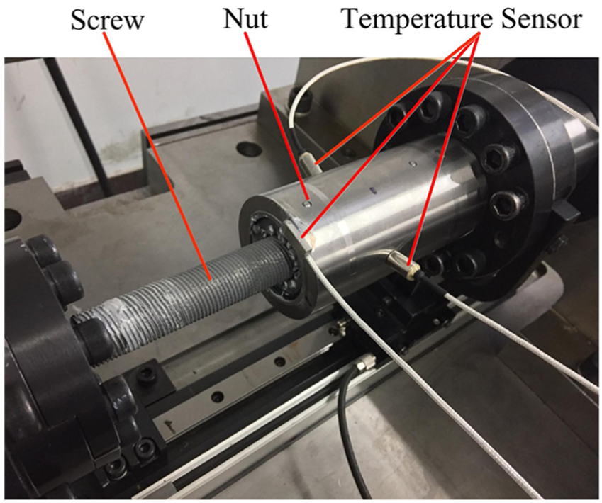
The experiment under 8000 N.
The sampling interval of the thermal imager is 400 s, and the sampling result is shown in Figure 9. The experimental results of different positions are compared with the simulation results, as shown in Figures 10–12.

Temperature shift diagram of #3 on the screw.
Temperature shift of #1 on the nut.
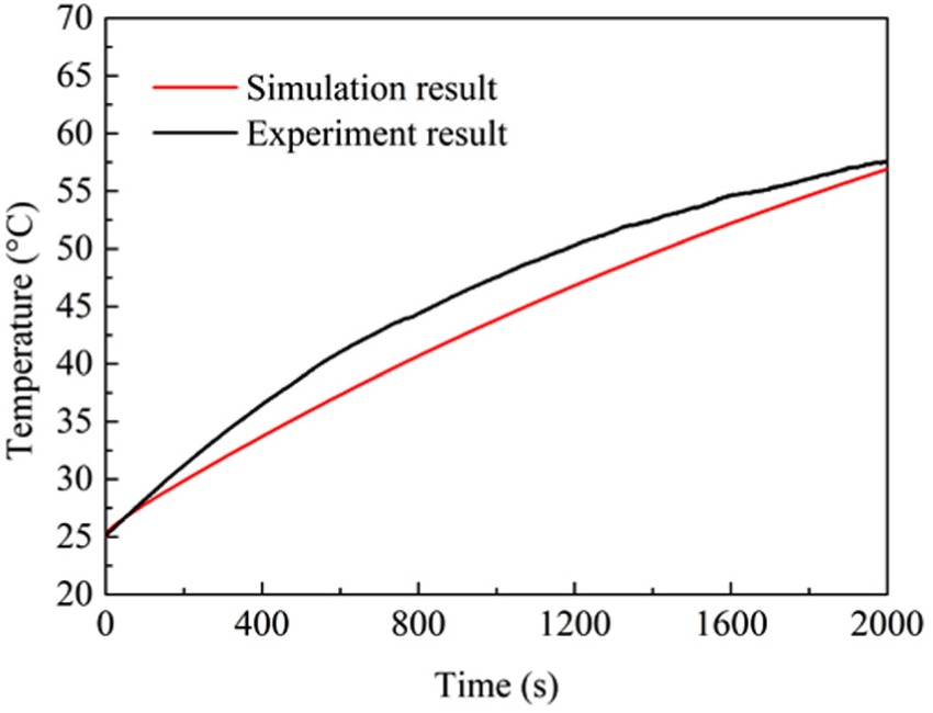
Temperature shift of #2 on the nut.

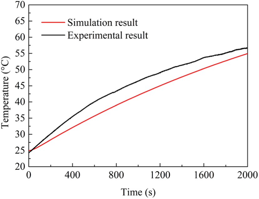
Temperature shift of #3 on the screw.
It can be seen from Figure 9 that the temperature of the screw monitoring point reaches 68.7°C and the temperature rise is 43.7°C after 2000 s, which shows that SPRSM has a serious heat output in practice. Compared with the experimental and simulation results at different monitoring points shown in Figures 10–12, the errors are within the tolerance range of 9%. Compared with the temperature rise of #1 and #2, the temperature rise at #3 on the screw is the highest.
The advantage of the finite element method in calculating temperature rise is that the influence of elastic lag, lubricating oil viscosity, friction torque, and thermal convection on temperature rise is fully considered. At the same time, the finite element model is established, and the heat source generated by the relative motion of roller and screw is simulated by moving thermal load. The drawback is that the calculation time of moving the thermal load using ANSYS command stream is very long, which leads to heavy computational burden.
The reasons for the errors between the experimental results and the simulation ones are as follows:
The simplified transmission system model of moving heat source is adopted in this article. Only if the step size of moving load is small enough, then it can be more suitable to the actual working process. But the step size is smaller, the longer the computation time is taken using APDL command-stream calculation method. Considering the limited computer space, the step size of this study is set to 20 mm.
The convection coefficient may vary in the experiment, but it is assumed a constant in the ANSYS simulation.
The friction torque is calculated without the consideration of machining and manufacturing, which is different from the experiment.
Conclusion
The temperature rise affects the service life and working precision of SPRSM. In this article, the thermal model of SPRSM is established, which is used to predict the thermal behavior of SPRSM. The temperature experiment is designed to verify the validity of the thermal model based on finite element method. The conclusion of this article is as follows:
The thermal analysis model of SPRSM is established, the thermal boundary conditions are analyzed, the simulation results are obtained using ANSYS, and a reasonable and effective experimental verification method is proposed.
According to the comparison results of temperature rise at different monitoring points, the calculated temperature rise is in agreement with the experimental value in the tolerance range of 9% during the 2000 s. The proposed finite element thermal model is reliable for predicting and analyzing the thermal characteristics of SPRSM.
Footnotes
Handling Editor: Shengfeng Qin
Declaration of conflicting interests
The author(s) declared no potential conflicts of interest with respect to the research, authorship, and/or publication of this article.
Funding
The author(s) disclosed receipt of the following financial support for the research, authorship, and/or publication of this article: This work was supported by the National Natural Science Foundation of China (grant nos 51505381 and 51275423), 111 Project of China (grant no. B13044), and Excellent Doctorate Cultivating Foundation of Northwestern Polytechnical University.