
Abstract
In this article, a drum type of transmission device has been developed, which is a double-layer cylinder structure. The working clearance between the inner and the external layers of the device has been filled with intelligent material named magneto-rheological fluid. To use it for tension regulation, theoretical model of its output torque has been constructed based on Bingham’s theory, and the coupling relationship between mechanical structure, electromagnetic circuit, and magneto-rheological fluid is analyzed and simulated using finite element analysis. Higher flux is directed onto the magneto-rheological fluid and greater shear frictions are generated subsequently. The design is practical, and a special seal mechanism which is a combination of magnetic seals and labyrinthine seals is applied in this research to improve sensitivity and to reduce leakage of the device. Then, experiments on prototype indicate that this device has significant advantages of quicker response, larger output, and less heat compared to traditional magnetic particle clutch and some existing disk-type magneto-rheological brakes which were recently reported. The new device may be applied widely in the related winding tension control field in the future.
Keywords
Introduction
Magnetic particle clutch is a magnetic–elastic conversion equipment that utilizes magnetic energy to achieve torque transmission. It has been commonly applied in the following fields: packaging, paper making, printing, and textile industry. Sheets and tapes of paper, plastic film, and fabric products need to be transmitted or wound under the proper control of certain tension. A magnetic particle clutch or brake is a perfect executive element.
However, magnetic particle clutch also has its disadvantages such as sharp rise in temperature due to long-time dry friction, as well as the variation of torque characteristics due to uneven distribution, accumulation, or solid hardening of magnetic particles. Therefore, this study attempts to introduce a torque transmission device based on smart material named magneto-rheological fluid (MRF). MRF has been applied in research and applications for several years because of its rapid, reversible, and controllable transformation between solid- and liquid-like states through the application of an external magnetic field. Raju et al. offer a recent progressive review on different types of the magneto-rheological (MR) materials, modeling of them, and MR material–based devices. They point out that the majority of MR brakes and MRF-based clutches are drum type, inverted drum type, T-shaped rotor type, and disk type. 1 Fitrian et al. 2 believe that rotary MR damper has several comparative advantages over linear MR damper. Olabu and Grunwald 3 present the state-of-the-art of an actuator with a control arrangement based on MRF technology. Sun et al. 4 present a novel variable stiffness and damping of an MRF damper. Attia et al. 5 introduce a theoretical and experimental study of MRF disk brake. Sukwani and Hirani 6 describe the design procedure of MR brake and discuss the effect of MR gap on its braking torque. However, most of these researches are mainly concerned with the problem of clutch and braking in power transmission; research and application on using MRF for tension regulation has seldom reported.
The aim of the present work is to design a novel rotary MR torque converter with practical structure for tension regulation. Its performance is to be investigated experimentally as well as theoretically in the study. We utilize the change of excitation current to precisely and quickly regulate output torque without overheating and specific water cooling system. Hence, it is quite appropriate for tension regulation in winding speed level of 400 or 500 m/min at present.7–9
MRF and its characteristics
MRF is an intelligent material, which changes rapidly and reversibly with the external magnetic field. Its coefficient of viscosity and shear yield strength can alter within several orders of magnitude higher than electro-rheological fluids in several milliseconds. Meanwhile, the relationship between magnetic field and shear yield strength of MRF remains stable. Once the external magnetic field disappears, its structure and property will recover instantly. The characteristics of MRF are suitable for the real-time control of torque transmission. 10
This study utilizes MRF-J01 type produced by the Chongqing Materials Research Institute. According to the data provided by the manufacturer, its dynamic viscosity under zero external magnetic field and under 20°C is 0.092 Pa·s.
Characteristics of MRF-J01 are shown in Figure 1. Figure 1(a) presents the magnetic flux density with magnetic field intensity, and Figure 1(b) shows the shear stress with magnetic field intensity.

Characteristics of type MRF-J01 magneto-rheological fluid: (a) magnetic flux density with magnetic field intensity and (b) shear stress with magnetic field intensity.
In the figure, B is the magnetic flux density of the magnetic circuit, H is the magnetic field intensity of the magnetic circuit, and
According to the relationship curve of magnetic flux density, magnetic field intensity, and shear stress, the equation with curve fitting method can be approximately expressed as

Structure of the new type tension control device
A new type of transmission device has been designed in this study whose output torque can be controlled by adjusting electric current; its inner structure is shown in Figure 2.

(a) 2D and (b) 3D structures of the new type magneto-rheological torque converter.
The new device consists of three parts: shell system, power input shaft system, and power output shaft system. The shell system is composed of right part and left part, with a rectangular-section annular groove in the middle to place the excitation coil. The power input shaft system includes input shaft and outer rotor, which are supported by bearings on the shell. The power output shaft system contains the combination of output shaft and inner rotor, which are also supported on the shell, and meanwhile have the center axis coinciding with output shaft. The radial clearance with 0.5–2 mm width between the inner and the outer cylinders is filled with MRF; we utilized the properties that shear yield strength of MRF would change with external magnetic field variation to adjust torque transmission in real time. Torque transmission between input shaft and output shaft is generated, and output torque can be controlled by adjusting electric current.
The device for tension control is required to have adequate and steady output torque, rapid and sensitive response, and ability of temperature maintenance in the process of long-time working. This structure has taken the matured ones of magnetic powder clutch for reference and meanwhile tried to meet the special requirements for MR torque transmission. First, a drum type rather than disk type is used in this device. Then, reduction in output torque in a drum-type device due to outward aggregation of magnetic particles by centrifugal pull can be avoided. Second, practical designs which draw lessons from magnetic powder clutch ensure that the device has enough assembly accuracy. Third, because friction in the new type device belongs to wet friction, and input rotor is equipped with fan blades on both sides to improve the heat dissipating capability using air cooling, excessive rise in temperature will be avoided. Finally, in this MR torque converter, based on the good characteristics of MRF, a new structure of non-contact sealing mechanism is developed. Mechanical labyrinth seal and magnetic seal are used together to prevent fluid leakage meanwhile to reduce friction under traditional contact seal. It will make full use of the good performance of MRF.
Design of magnetic circuit
The width of the work clearance is filled with MRF as much as possible, and at the same time, achieving its balancing magnetic saturation is the most important factor to measure whether the design of the magnetic circuit is appropriate. It is generally believed that MRF reaches magnetic saturation when the magnetic flux density ranges from 0.4 to 0.9 T. 11 The MRF-J01 reaches magnetic saturation when the magnetic flux density B = 0.5 T based on the data from the manufacturers. 12
Before designing the magnetic circuit, the following assumptions are made:
Magnetic flux leakage is inevitable in the magnetic circuit. In order to simplify calculations, ignoring the effect of magnetic flux leakage, we assumed that the magnetic circuit goes through the same magnetic flux. In other words, there are equal magnetic fluxes everywhere in the loop;
MRF is well distributed in the working clearance;
There are gapless in the binding surface of magnetic yoke, as well as non-magnetic drop;
The influence of coil insulating framework on electromagnetic field can be ignored.
First, Ohm’s law of magnetic circuit indicates that the entire magnetic potential of the magnetic circuit is equal to the algebraic sum of magnetic flux of each section in the magnetic circuits to multiply its own reluctance. Calculation is seen later. 13 The right-hand side of the equation can also be understood as the magnetic circuit of magnetic pressure drop
where

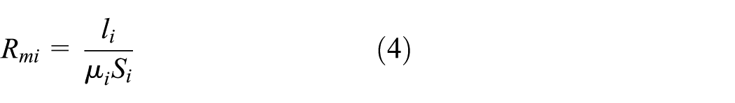
where
The magnetic induction can be expressed as

where
If any branches exist in the magnetic circuit, the first law of magnetic circuit would be used that at any branch point in the magnetic circuit, the algebraic sum of the total magnetic flux would be zero14,15

Meanwhile, by the second law of magnetic circuit that along any closed magnetic circuit, the algebraic sum of all parts of the magnetic pressure drop equals to all magnetic potential in the loop which surrounded16,17

According to the structure scheme, the magnetic circuit should be simplified as shown in Figure 3(a). The magnetic circuit is divided into a total of 12 sections. Sections 1 and 2 are the shell (steel); section 3 is the non-working clearance (air) in the magnetic circuit; section 4 is the outer ring (steel) in the magnetic circuit; section 5 is the part of working clearance (MRF); sections 6–8 are the part of inner ring (steel) in the magnetic circuit; and sections 9–12 are the magnetic circuit on the left side, respectively. In the middle point division, in the width direction of the outer ring, a magnetic isolation ring made of stainless steel is set to ensure that the vast majority of magnetic field lines should go through the working clearance before they can return to the shell. The geometric size of each component is shown in the figure. The width of the working clearance is h and the non-working clearance is c. Because sections 2–6 and sections 7, 8, 9, 10, and 12 are symmetrical, the equivalent magnetic circuit can be expressed as shown in Figure 3(b). 18

Model for the magnetic circuit calculation: (a) magnetic circuit design and (b) equivalent magnetic circuit diagram.
Finite element simulation of magnetic field’s nearby working clearance
Finite element simulation using ANSYS software shows distribution of magnetic lines of force around work clearance as shown in Figures 4–7. Some main parameters of the model are as follows: work clearance is 1 mm, diameter of excitation coil is 186 mm, number of turns is 800 mm, and diameter of enameled wire is 0.75 mm. The exciting coil is made of copper wire whose relative permeability is 1 H/m. The inner and outer cylinders were made of 45 steel, and its permeability is defined by the B–H curve of no. 45 steel. The resistance gap is filled with MRF (MRF-J01) from the Chongqing Materials Research Institute. The current density in the exciting coil in this simulation was set at 2 A.

Distribution of magnetic lines.

Magnetic field intensity.

Magnetic flux vector distribution.

Magnetic induction distribution.
According to the original geometric model, a finite element analysis model was established; major technical parameters were defined; and meshing and setting boundary conditions were finished according to simulation requirements. And then, the distribution of the excited magnetic field was obtained by the electromagnetic finite element simulation.
In Figure 4, we can find that the majority of magnetic field lines went through the working clearance before they returned to the shell. In Figures 5–8, we can observe that the magnetic flux density of the nearby working clearance ranges from 0.37 to 0.56 T, which approximately approached the magnetic saturation of MRF-J01. The results also show that the magnetic flux density increases with the increase in the current.

Three-dimensional magnetic induction distribution.
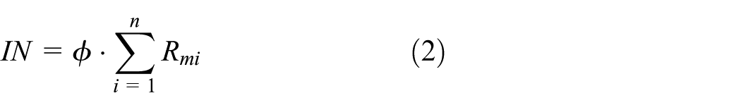
Theoretical model of output torque
The Bingham constitutive model is expressed in the following equation

where τ, τy, η, and
Due to the fluid property of MRFs, the angular velocity at different radii changes. Let u denote the circumferential velocity of MRFs at radius r, and the derivative of the velocity versus radius is expressed as

where
The theoretical output torque of MRFs at radius r is expressed as

Equations (9)–(11) are solved simultaneously; let M1 denote the torque produced by MRF’s plastic yield strength under magnetic field and M2 denote the friction resistant torque produced by MRF’s viscosity under zero magnetic field. Now, the output torque of this MRF tension control device can be divided into two parts. If R1 and R2, respectively, denote the external and the internal radii of the inner and the outer cylinders, and L represents the work width of MRF. Then, (R1 + R2)/2 is chosen as the marked radius. Because the magnetic field intensity decreases rapidly with the reducing radial dimension, friction resistant torque produced by MRF in the side face clearance can be neglected. 19 After simplification, two parts of torque and the whole output torque are shown, respectively, in equations (11)–(13) 20


where Δω represents the difference in angular velocity.
For example, the main parameters are taken as L = 55 mm, R1 = 89.7 mm, R2 = 88.2 mm, and η = 0.092 Pa·s. Then, the torque produced by MRF’s plastic yield strength can be calculated using equation (9) under different magnetic induction intensities; results for 0.1, 0.25, 0.5, 0.75, and 1.0 T are shown in Table 1. Shear stress of MRF can be obtained according to Figure 1 and equation (1). 20
M1 and τy under different magnetic induction intensities.
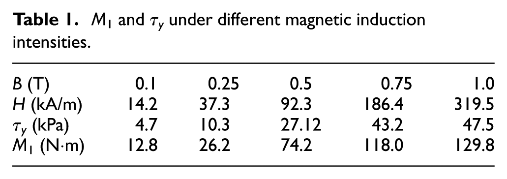
By comparison, MR device provides larger torque than magnetic particle clutch with similar size. 21
Experiments on prototype
According to the design, prototype parts were manufactured and assembled, as shown in Figure 9.

Prototype production.
Then, a prototype test system was carried out as shown in Figure 10: the output shaft and the input shaft of the prototype were connected with two sets of torque and speed sensors, and the output terminal of the sensor was linked with a magnetic powder loader by shaft coupling. Exciting current of the prototype and magnetic powder loader were controlled by two sets of adjustable DC power supply.

Prototype test system.
The static characteristics, mechanical properties, and regulation characteristics of the prototype were obtained, as shown in Figures 11–13, respectively.
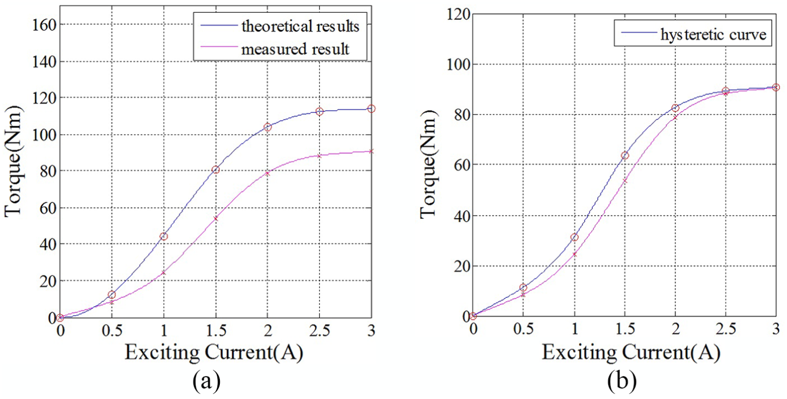
Static characteristics of prototype: (a) measured and theoretical results and (b) hysteresis curve.

Mechanical properties of prototype.
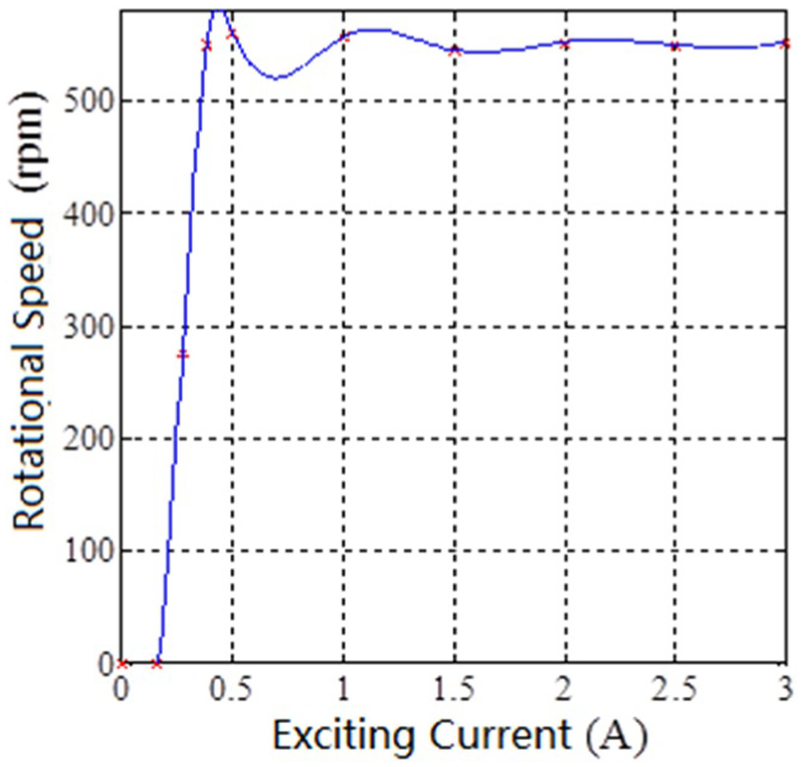
Regulation characteristics of prototype.
In Figure 11, we can find that the output torque increases with current and that in the initial segment (0–1 A) of the static characteristic curve, it has a small slope, which may be due to the poor work clearance and liquidity of MRF. But after working a period of time, the static characteristic curve of the middle section (1–2 A) has a larger slope, and the torque changes with the steady increase in the excitation current and presents linear relation.
The results also show that the theoretical and measured values of output torque are basically in agreement with each other. The reason that the value of the experiment is lower than the theoretical value is very complicated. First, the torque converter is a mechanical, electrical, magnetic, and liquid complex: all are coupled with each other. During design period, there always exist many contradictions in requirements that are put forward from different angles. For example, the smaller the working or non-working clearance, the better the magnetic field effects occurred. But this will bring more difficulty in MRF injection or production and the assembly of the device. Similarly, increasing the current will result in cooling problems. Moreover, the theoretical calculations often need some simplification and assumption. This is also the main reason for the difference between the theoretical value of the torque and the measured value. The reason may also relate to the quality defects in manufacturing and installation process of prototype.
From hysteresis curve, we can see that the hysteresis phenomenon exists. But the degree of hysteresis is not significant in an acceptable range.
According to Figure 12, if the speed of the input shaft is set at 550 r/min, then when load is less than 60 Nm, the speeds of the input shaft and the output shaft are similar, and the prototype works in the synchronization operation mode. When load is greater than 60 Nm and less than 80 Nm, the speed of the output shaft is slower than the input shaft, and the prototype works in the slip operation mode. When load is greater than 80 Nm, the speed of the output shaft is zero, and the prototype works in the braking state.
From Figure 13, it can be seen that when the excitation current is less than 0.16 A, the speed of the output shaft is zero. When the current is more than 0.16 A and less than 0.38 A, the speed of the output shaft changes between zero and the speed of the input shaft; here, the prototype works in the slip mode. When the current is more than 0.38 A, and the speed of the output shaft is set at 550 r/min, the prototype works in the synchronization operation mode.
Experiments on prototype also show that the increase in temperature after working for 5 h is always stabilized at 80°C, and it is improved greatly when compared to the magnetic particle clutch.
Conclusion
In this article, we studied a new type of transmission device which can generate larger output torque without excessive rise in temperature, quick response to adjusting electric current, and thus can be more easily controlled compared to magnetic particle clutch. By using the first and second laws of magnetic circuit, the interaction effect analysis of the electric field, magnetic field, and MRF has been carried out and the mode of the magnetic circuit is derived. Electromagnetic finite element analysis is employed to simulate the magnetic circuit of this MRF torque converter. This can help determine the main parameters of this MRF tension regulation device. From Bingham’s constitutive equation of MRF, the theoretical model of output torque of the new transmission device was found and was applied to numerical example. Experiments were conducted on a prototype, and the results show that this transmission has a series of merits: easy to control, low control power, wide line range of regulation, and stable speed regulation. The new one may be applied widely in some winding tension control cases in the related field in the future.
Giving a review of the whole study, there are some limitations to it. First, due to the condition of testing, our study uses the data of characteristics of MRF-J01 provided from the Chongqing Materials Research Institute. This may slightly reduce the credibility of the conclusion. Second, the prototype of winding tension control system used in this new transmission has not yet completed and relevant experiment should be carried out. This is one of the areas our team will investigate further.
Footnotes
Handling Editor: Yangmin Li
Declaration of conflicting interests
The author(s) declared no potential conflicts of interest with respect to the research, authorship, and/or publication of this article.
Funding
The author(s) disclosed receipt of the following financial support for the research, authorship, and/or publication of this article: This study was financially supported by the research from the National Natural Science Foundation of China (grant no. 51775260), Key Research and Development Plan of Jiangsu Province (grant no. BE2017167), and Major Programs of the Nanjing Institute Technology–Tech Research Program (grant no. CKJB201301).