
Abstract
Conventional high-frequency cleaners utilize functional materials (e.g. piezoelectric ceramics, magnetostrictive materials) excited by electrical signals to realize high-frequency vibration, even ultrasonic vibration. However, it is difficult to produce a large force without sacrificing bandwidth because of the physical characteristics of materials themselves. Therefore, a high-frequency high-power cleaner driven by electro-hydraulic excitation is proposed. Only a few studies are performed on electro-hydraulic cleaners, owing to the limitation of frequency bandwidth of the electro-hydraulic system. Thus, a rotary valve named two-dimensional valve is improved and adopted to improve high-frequency performances of the electro-hydraulic cleaner. In this article, a two-dimensional rotary valve with a linear variable differential transformer is designed, and the vibration characteristics of the electro-hydraulic cleaner controlled by this valve are discussed in detail, especially vibration acceleration, vibration frequency, and pressure amplitude. A prototype of the electro-hydraulic cleaner is modeled and both a theoretical analysis and experimental investigation are carried out. Theoretical and experimental results indicate that the electro-hydraulic cleaning system outputs sinusoidal vibration waveforms, especially in a high-frequency domain, which could realize the vibration frequency of 2669 Hz. The measured waves at different frequencies (below the resonant frequency) demonstrate different distortions compared with the sinusoidal waveform. These distortions can be associated with the hydraulic resonance. At hydraulic resonance (1903 Hz), the amplitude is increased significantly and the vibration waveform becomes more pronounced. Nevertheless, the study does provide an access to the electro-hydraulic high-frequency vibration applied in cleaning or other engineering cases.
Keywords
Introduction
Traditional cleaning methods,1,2 for example, jet cleaning, mechanical cleaning (scraping, brushing), or chemical cleaning, have some drawbacks. These methods are insensitive to the cleaning of components with the characteristics of complex structure and have a large consumption including manual labor and long duration. To solve these problems, different types of high-frequency cleaning have been proposed by researchers. High-frequency cleaner have applications in the present because they are efficacious, fast, and environment friendly. High-frequency cleaning is a method of immersion cleaner which is able to remove dirty and small particles purely.
Existing high-frequency cleaners mainly utilize functional materials (e.g. piezoelectric ceramics, magnetostrictive materials3,4) excited by electrical signals to realize high-frequency vibration, even ultrasonic vibration.5,6 Despite existing high-frequency cleaning scheme has been widely used in engineering cleaning field, especially in membranes scale removal and medical equipment decontamination8,9 and so on. It is difficult to produce a large force without sacrificing bandwidth because of the physical characteristics of materials themselves. In heavy industries, after machining or assembly of individual parts, most engineering products must be cleaned free of cutting oil residues and swarf. This will also be true when parts are dismantled and recycled because ingrained debris must be removed. Due to some drawbacks with traditional methods,1,2 their dependence need to be weakened and be replaced by high-frequency cleaning. Therefore, to realize high-frequency vibration and large output, a high-frequency high-power cleaner driven by electro-hydraulic excitation is proposed.
There has been significant research on the vibration characteristics of high-frequency vibration systems used in cleaning or other cases. Liu et al. 10 researched the synchronization motion of double hydraulic cylinders controlled by high-speed on–off valve and found that the collaborative synchronization control is effective to eliminate displacement error between the double cylinders which results from the different load environment and other disturbances. Wan et al. 11 proposed a dynamic self-adaptive mixed control method. This method can improve the hydraulic system’s dynamic characteristics, and good tracking and high stability are observed under the condition of high-frequency response. Shen et al. 12 established an experiment and its nonlinear model to compare control performances of these controllers, and a number of experiments were carried out on an actual electro-hydraulic vibration table system. Different controllers have been addressed including the proportional–integral–derivative (PID) controller, the thrust vector controller (TVC) and its improved controllers, the feed-forward inverse model controller (FIMC) and its improved controller combined with modeling error, and adaptive controllers and their combined controllers. It can be seen from these simulation and experimental results that the methods combining multiple controllers can be used to further improve the acceleration frequency characteristics within the low-frequency band. Sheng and Li 13 studied the design of the robust controller for the electro-hydraulic loading system and proposed a hybrid control scheme. This scheme is based on the robust control theory and does not rely on the exact mathematical model, because of the nonlinear hydraulic system. The simulation results of the electro-hydraulic loading system with a high-frequency dynamic load superimposed on a large static load experimental problem show that this scheme can effectively improve the robustness of the electro-hydraulic system in the high-frequency region. A special excitation source as an application is produced by system flow and water hammer coupling. 14 The pressure fluctuation can be controlled independently and achieve the excitation frequency of 90 Hz. It is usually found in separation or compaction engineering applications characterized by large output forces.
However, only a few studies are performed on electro-hydraulic cleaners, owing to the limitation of frequency bandwidth of the electro-hydraulic system. To solve this problem, different types of high-frequency electro-hydraulic vibration systems have been proposed by researchers. A 1-kHz servo-hydraulic fatigue testing system has been developed by MTS Corporation, and it will be integrated for high-temperature fatigue testing and crack growth testing in Michigan Technological University. 15 An exciter using a GSF series servo valve has been developed by Beijing Institute of Automation and is applied in the linear friction welding system, of which the highest excitation frequency is up to 125 Hz. 16
A rotary valve named two-dimensional (2D) rotary valve as an enabling technology has been used in hydraulic systems. Ruan 17 proposes a new scheme for an electro-hydraulic vibrator excited by this 2D valve, which significantly extends the frequency range compared with that of vibrators controlled by conventional servo valves. Ren and Ruan 18 give an analytic solution of the vibration waveform excited by this electro-hydraulic system and the mathematical formulation of the harmonics is also derived. In this article, a 2D rotary valve with a linear variable differential transformer (LVDT) is designed and the vibration characteristics of the electro-hydraulic cleaner controlled by this valve are discussed in detail, especially vibration acceleration, vibration frequency, and pressure amplitude. The experimental study on the prototype cleaner shows that this scheme can widen the electro-hydraulic system’s working frequency up to 2669 Hz and can output sinusoidal vibration waveforms when the working frequency exceeds the hydraulic resonance domain. This study provides access to the electro-hydraulic high-frequency vibration applied in cleaning or other engineering cases.
The remainder of this article is organized as follows. Section “Description of the working principle” describes the working principle of the electro-hydraulic cleaning system and the design of the improved 2D rotary valve. Section “The mathematical model” establishes the mathematical model of this electro-hydraulic system and details the excitation characteristics. Section “Experiment and results” describes the experimental design, presents the results of the experiment, and tests the advantage of the proposed method through a comparative study. Conclusions are summarized in section “Conclusion.”
Description of the working principle
High-frequency electro-hydraulic cleaner
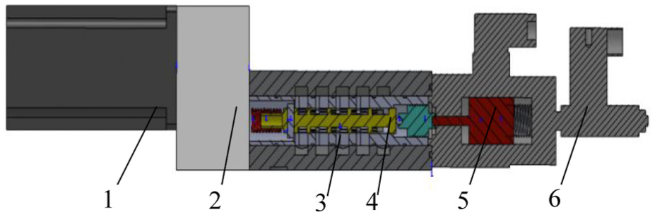
A high-frequency electro-hydraulic cleaner mainly consists of a 2D rotary valve, a hydraulic actuator, and a cleaning box, the details of which are shown in Figure 1. This hydraulic excitation is actually a hydraulic actuator, making reciprocating motion of the piston under the alternative flow rate into or out of its working chambers created by a 2D rotary valve, the spool of which is continuously driven by a servo motor so as to create an alternatively varied valve port area. The P and T ports are arranged on both sides of the hydraulic cylinder to connect separately to the hydraulic pump and the tank to provide power to this system. The reciprocating piston further results in an excitation of the cleaning box as a load connected on the cylinder rod. The cleaning box is installed on the sliding rail by a sliding bearing seat. When the hydraulic piston rod drives the cleaning box reciprocating vibration, the contaminated components (especially heavy parts) in the cleaning box are cleaned using this hydraulic excitation.

Structure of the high-frequency electro-hydraulic cleaner.
Improved 2D rotary valve
The working frequency of the conventional electro-hydraulic excitation system constructed by a servo valve and a hydraulic cylinder or a motor is to a large extent limited to a fairly narrow range because of the relatively low frequency response capability of the servo valve. Therefore, a 2D control rotary valve used in the high-frequency cleaning system is proposed and improved instead of the servo valve to realize the high-frequency excitation. In the improved 2D rotary valve, the rotary and sliding motions of the spool are independently exploited to control the frequency and magnitude of the excitation waveform, respectively. The frequency of the excitation waveform is determined by the rotary speed of the 2D rotary valve, number of grooves distributed on a spool land, coupled pattern of the groove number on the spool land, and the number of windows on the spool sleeve. By adjusting these factors in the 2D valve design, the proposed scheme of the high-frequency electro-hydraulic cleaner is apt to realize high-frequency vibration. The amplitude of the excitation waveform is controlled by the axial displacement of the spool.
The improved 2D rotary valve is shown in Figure 2. The spool of the 2D rotary valve is continuously driven by a servo motor. Because it is limited by the frequency response of this actuator, a gearbox with 1:4 gear increase is designed to realize high rotary speed of the spool. The porting of the fluid into and out of the cylinder chambers is accomplished using a series of grooves asymmetrically distributed on the spool coordinated with the windows distributed uniformly on the sleeve. The “alternate variation” of the porting area depends on the rotary speed of the spool. The spool of the 2D rotary valve is also driven by an electromagnet. The displacement of the main spool can be detected with an electrical displacement transducer (LVDT) and fed to control the coil current of the magnet driving the valve. Consequently, the 2D rotary valve is controlled accurately, which is completely analogous to the control scheme of the servo valve.
Improved 2D rotary valve with an LVDT.
The mathematical model
Excitation frequency
The “alternately varied” valve port area is formed between the grooves on the spool and the windows on the sleeve. The window on the sleeve is T-slot, of which the bottom side is designed to match the spool to form throttling orifices, whereas the top side is used to compensate for the steady-state flow force by directing the fluid that leaves the valve chamber back on the spool. The full port and partial port patterns of the coupling valve port between the grooves and the windows are designed, as shown in Figure 3(b) and (c), respectively.
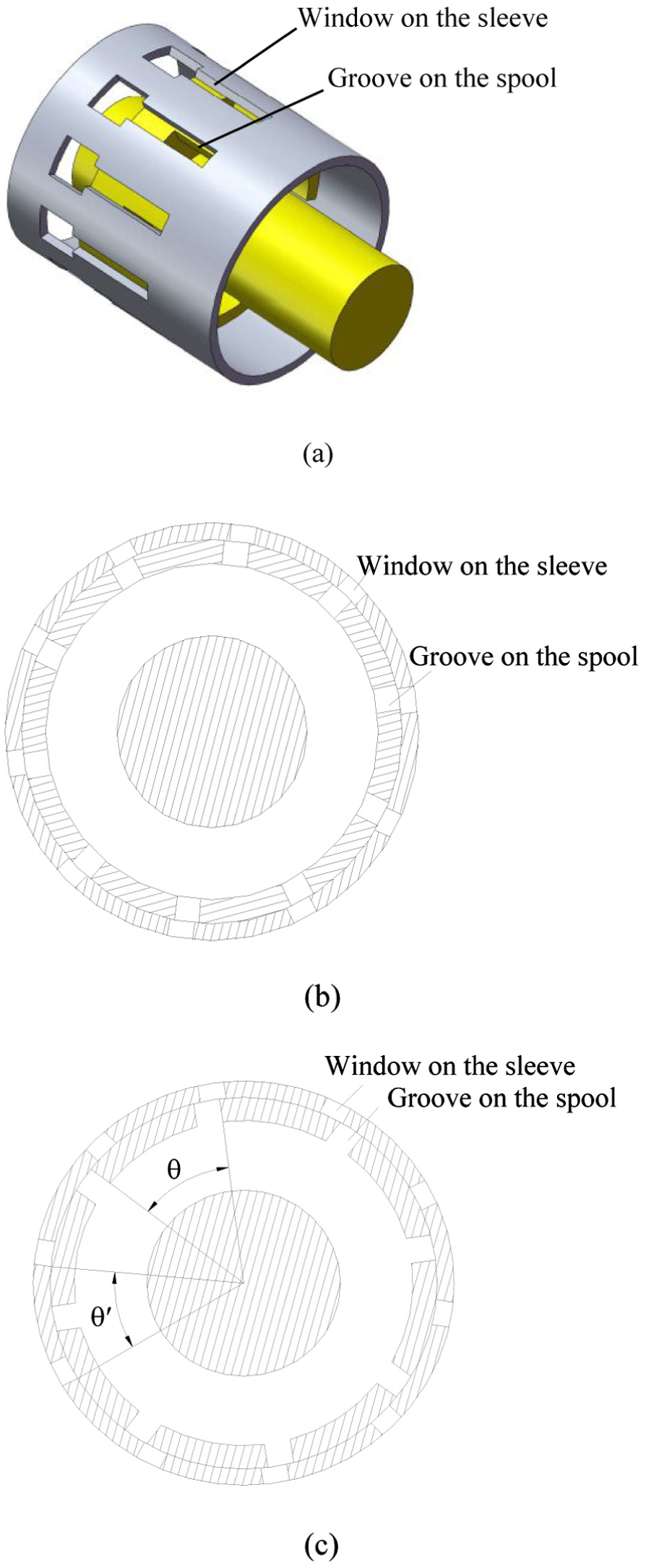
Coupling pattern between the grooves on the spool and the windows on the sleeve: (a) structure of arrangement of the spool and the sleeve; (b) sectional view of the arrangement of the spool and the sleeve (full port pattern); and (c) sectional view of the arrangement of the spool and the sleeve (partial port pattern).
For the full port, the number of grooves on the spool land is equal to that of windows on the sleeve and all the valve port formed between the grooves and the windows will be open or close synchronously as the spool rotates continuously. Therefore, the full port valve’s excitation frequency f can be expressed as

where n is the rotary speed of the spool and z is the number of the grooves on a single spool land.
For the partial port, the number of grooves is different from that of windows and the numbers of both grooves and windows selected should satisfy a special relationship, that is, the absolute difference between the central angle of the groove and that of the window should be fully divided by the number of grooves or windows, and the result should be equal to half the number of grooves or windows. This relationship can be described using the coefficient β, that is

where θ is the central angle of the groove and
Apparently, the frequency of the reciprocating motion of the piston controlled with the 2D rotary valve is proportional to the rotary speed of the spool and the number of grooves on a single spool land. It is also related to the coupling pattern between the grooves on the spool and the windows on the sleeve, which is indicated by a coefficient β. Actually this coefficient is the number of grooves connected to the window. Therefore, the excitation frequency can be expressed as

Taking the partial port shown in Figure 3 as an example, θ = 45°,
Compared with the full port pattern in the former design,17,18 the partial port pattern is easy to realize a higher excitation frequency. However, this high frequency is achieved at the price of sacrificing the magnitude of the opening area of the valve port.
Excitation peak
The volume and continuity expression can be combined to yield

where QL is the load flow, Ap is the area of the piston, xp is the displacement of the piston, Ctp is the total leakage coefficient of the piston, pL is the load pressure difference, Vt is total volume of the fluid under compression in both chambers, Vt = 2V0, V0 is the volume of the forward or return chamber, and βe is the effective bulk modulus of the system.
Assuming that the load consists only of inertia, we obtain

where p1 is the forward chamber pressure, p2 is the return chamber pressure, Mt is the total mass of the piston and load, and vp is the velocity of the piston.
Assuming that the initial position of the excitation is in the middle of the cylinder, in the interval 0 < t < T/4 (T is the period of excitation), both line pressures vary in equal but opposite amounts from ps/2 (ps is the system pressure) until the forward chamber pressure becomes ps and the return chamber pressure becomes zero. During this interval, assuming zero leakage flows and equal chamber volumes, equations (3) and (4) can be combined and solved for a step change in flow from vp0Ap (vp0 is the initial velocity of the piston) to zero and subject to the initial conditions of pL = 0 at t = 0. The result is

where
If p1 = ps at t = T/4, this is the critical saturation. Substituting these values, the relationship between the pressure peak, hydraulic natural frequency, and the excitation period is

Structural parameters
The structural parameters of the high-frequency electro-hydraulic cleaner used in the simplified expressions are shown in Table 1.
Structural parameters.

Experiment and results
Experimental hardware
The experimental system mainly consists of the high-frequency electro-hydraulic cleaner and the controller. The prototype high-frequency electro-hydraulic cleaner is shown in Figure 4 and the controller is illustrated in Figure 5. An acceleration transducer which is a triaxial accelerometer (EA-YD-116 series; ECON) is used to detect the acceleration signals of the excitation (this study only shows the same direction of cleaning box vibration direction). Then the signals will be sent to the industrial computer to display, save and analysis. This experiment focuses on vibration characteristic parameters, for example, frequency, amplitude, waveform. In the controller, two special knobs are designed to control the rotary speed of the servo motor (SGMGV series; YASKAWA) and the axial displacement of the electromagnet (GP61-4-A series; MOOG), respectively.
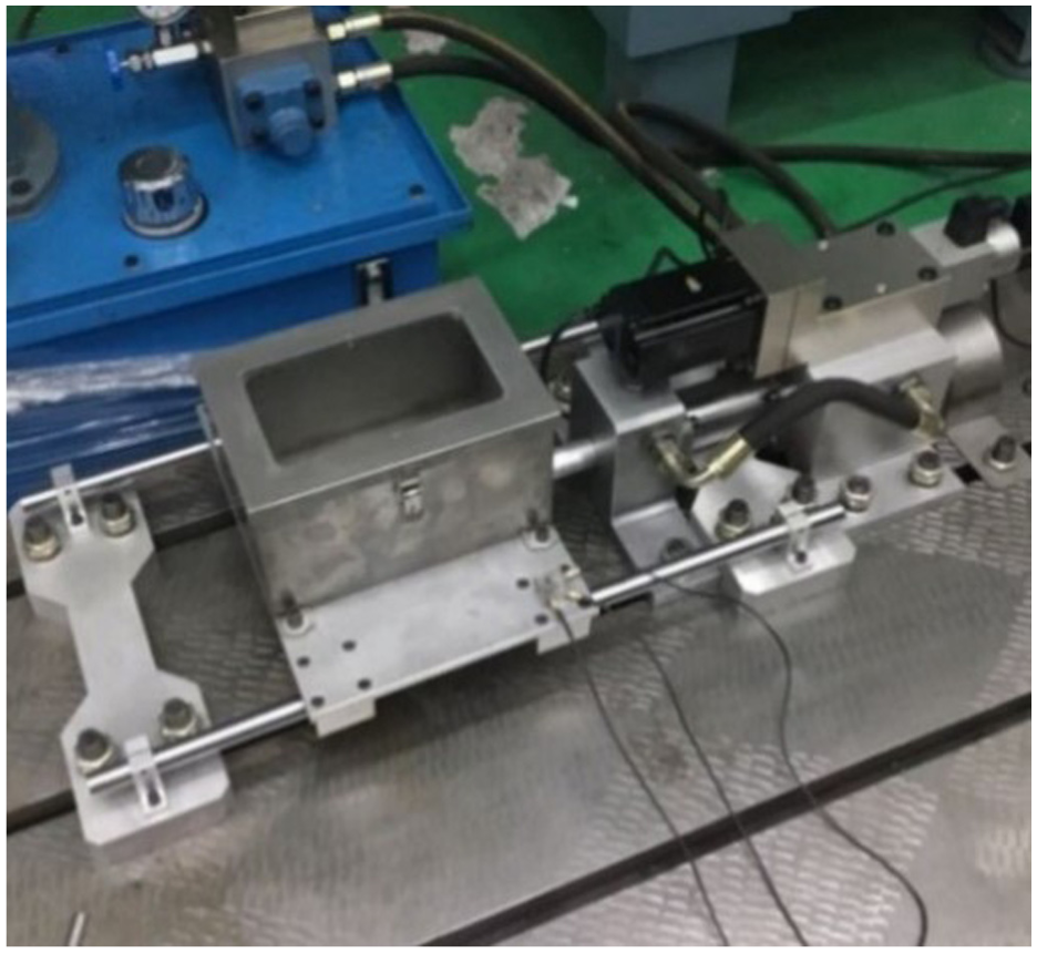
Prototype high-frequency electro-hydraulic cleaner.
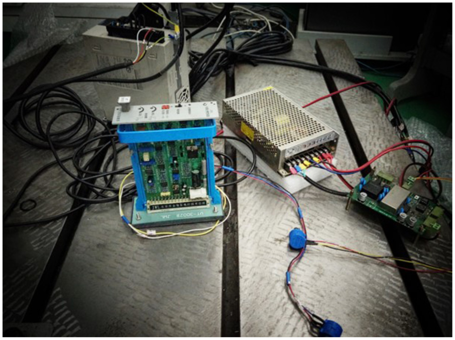
Controller.
The high-frequency electro-hydraulic cleaner is fixed on the T-shaped channel of the cast iron platform using the anchor bolts, of which the weight is nearly 100 times that of the whole electro-hydraulic cleaning system for avoiding the very strong effect of shock. Consequently, the weight of the foundation is large enough so that the influence on the vibration amplitude is less than 1% and acceleration is not exceeding 0.1 g.
Experimental results
Excitation frequencies and waveforms
In order to research and analyze the actual working frequencies of the high-frequency electro-hydraulic cleaner under different working speeds, the relationship between frequencies and waveforms is shown in Figure 6.

Cleaner working frequencies at different motor speeds.
The improved 2D valve and actuator have significantly extended the application of the electro-hydraulic cleaner’s frequency range and the upper frequency can reach 2669 Hz. In addition, the measured working frequencies at a different servo motor speed show an approximately straight line.
In the high-frequency domain range (2000–3000 Hz), the excitation waveforms with different rotary valve linear openings (60%, 80%, 100%) are shown in Figure 6. The working frequency of the excitation waveforms can be controlled by changing the rotary speed of the spool controlled by the speed of the servo motor, and the amplitude of the excitation waveforms can be adjusted by changing the rotary valve linear opening controlled by the axial displacement of the electromagnet. It can also be found from Figure 7 that the amplitude at the frequency of 1903 Hz is the most manifest.

FFT covering of excitation waveforms at different frequencies: (a) f =1903 Hz; (b) f = 2401 Hz; and (c) f = 2669 Hz.
Frequency spectrum
The corresponding fast Fourier transform (FFT) covering of excitation waveforms in the frequency range from 400 to 3000 Hz is obtained and shown in Figure 8. It is observed that the measured waves at different frequencies demonstrate different distortions compared with the sinusoidal waveform. These distortions can be associated with the hydraulic resonance.

FFT covering of excitation waveforms at different frequencies: (a) f = 602 Hz; (b) f = 995 Hz; (c) f = 1903 Hz; and (d) f = 2669 Hz.
At frequencies lower than the resonant frequency, the excitation waveforms are affected by hydraulic resonance, especially this situation is for the case in which the resonant frequency is an integer multiple of the excitation frequency. When the excitation frequency is 602 Hz (see Figure 8(a)), which is about one-third of the hydraulic resonant frequency, the effect becomes quite significant. Except the peak of the main frequency, there is another peak near 1900 Hz. The same is observed for the excitation frequency of 995 Hz, as shown in Figure 8(b). It can also be found that the output waveform of the hydraulic excitation system contains components of frequencies higher than that of the hydraulic resonance. Except the peak of the main frequency, there are other peaks near 1900, 2900, 3900, and 5000 Hz. This is due to when a certain order resonance frequency triggers the other components vibration (such as the force cells, hydraulic pipe, and frame, etc), similar to modulation. As the working frequency is 1903 Hz, the effect of hydraulic resonance became the most significant. The output amplitude is increased significantly, as shown in Figure 8(c). However, with reference to Figure 8(d), the hydraulic resonance has almost no effect on these excitation waveforms as the frequencies surpass the resonant frequency.
Hydraulic resonance
By increasing the speed of the servo motor (subsequently increasing the excitation frequency), the acceleration responses under the valve linear opening 80% are obtained and shown in Figure 9. With reference to Figure 8(c), the acceleration amplitude is the most obvious at resonant frequency (1903 Hz), which is increased considerably, and It is completely analogous to the sinusoidal waveform.
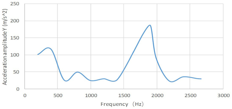
Acceleration amplitudes at different frequencies.
Conclusion
Efficient rotary valves are an enabling technology for applying digital control techniques to hydraulic systems. An improved 2D rotary valve with LVDT is designed and applied in a high-frequency electro-hydraulic cleaning system. The displacement of the spool can be detected with an electrical displacement transducer (LVDT) and fed to control the coil current of the magnet driving the valve. Consequently the improved 2D rotary valve is controlled accurately, which is completely analogous to the control scheme of the servo valve.
Only a few studies are available on the electro-hydraulic cleaners. The high-frequency electro-hydraulic cleaner is the subject of this article. The vibration characteristics of the electro-hydraulic cleaner controlled by this valve are discussed in detail, especially vibration acceleration, vibration frequency, and pressure amplitude. From these experimental results of vibration characteristics, the following conclusions can be made:
The improved 2D valve and actuator have significantly extended the application of electro-hydraulic cleaner frequency range and the upper frequency can reach 2669 Hz.
The prototype of the electro-hydraulic cleaner vibration frequency and amplitude can be controlled separately. The working frequency of the excitation waveforms can be controlled by changing the speed of the servo motor, and the amplitude of the excitation waveforms can be adjusted by changing the rotary valve linear opening controlled by the axial displacement of the electromagnet. The separate control for the electro-hydraulic cleaner facilitates the enhancement of the frequency range and the improvement of the accuracy.
When the cleaner’s working frequencies are lower than the resonant frequency, the effect of hydraulic resonance became more significant, and at frequencies higher than the resonant frequency, the hydraulic resonance has almost no effect on these excitation waveforms.
When the working frequency is 1903 Hz, the effect of hydraulic resonance became the most significant. At the same time, the output waveform is completely analogous to the sinusoidal waveform. In this scheme, the valve speed corresponding to the working frequency should be higher than (or equal to) the resonance frequency, to ensure the quality of working.
Not only the cleaning system but also other engineering cases can consider this electro-hydraulic excitation controlled by a 2D rotary valve. For example, this scheme is applied in fast forging machines, which will not only widen the working frequency, but also control the output waveform to improve the property of forging parts.
Footnotes
Appendix 1
Handling Editor: Zengtao Chen
Declaration of conflicting interests
The author(s) declared no potential conflicts of interest with respect to the research, authorship, and/or publication of this article.
Funding
The author(s) disclosed receipt of the following financial support for the research, authorship, and/or publication of this article: The authors are grateful to the National Science Foundation of China (Nos 51505338, 51405346, and 51605337), the Zhejiang Provincial Natural Science Foundation of China (Nos LQ16E050004 and LQ17E050003), and the Public Projects of Wenzhou City (No. G20150014) for their support.