
Abstract
Nowadays, thin-walled foam-filled structures have already been excessively used in automobile industry due to the superior energy absorption capacity and relatively light weight. The components in vehicle probably subject to lateral impact at any position in practice; however, most of the previous literature focused only on the bending behavior of structures under lateral impact at the mid-span. In this study, a hybrid structure of the structural epoxy foam Terocore® and two cylindrical tubes is comprehensively investigated under various lateral impact positions. The finite element model of the hybrid structure is established and then validated by the experimental results. From a numerical study, several design parameters, including the thicknesses of outer and inner tubes, the diameters of inner tubes, and the foam densities, are explored to exhibit great effects on the bending resistance of the hybrid structure. To find the optimal designs of the hybrid structure under different load cases, a system methodology, which is constructed by optimal Latin hypercube sampling, radial basis function model and multi-objective particle swarm optimization algorithm, is implemented. Compared with the original design, the optimization designs of different load cases perform better bending resistance, namely, higher specific energy absorption and lower peak crushing force. Therefore, the optimal hybrid structure can be considered as a practical candidate for energy absorbing under lateral impact.
Keywords
Introduction
The increasing requirements in vehicle safety and emission have led to a series of investigations into energy-absorbing structures with light weight. Thin-walled tubes have been widely used as the key structural components of the majority of transportation vehicles because of the outstanding energy absorption (EA) efficiency and light weight. 1 In the real world, about 90% of the involved structural members failed in bending collapse mode. 2 For this reason, it is practically significant to study the bending behavior of thin-walled structures under lateral impacts. Kecman 3 pioneered the investigation of the bending collapse behavior of rectangle and square section tube and Wierzbicki et al. 4 extended the concept of a superfolding element, which was developed originally for axially loaded columns, to the case of bending and combined bending and compression loading. Since then, a series of experimental and theoretical studies5–14 have been performed in this attractive field to investigate square and circular tubes subjected to static and dynamic loads.
To further improve the bending resistance and achieve higher EA to weight ratio, a series of research works were conducted by filling the hollow structures with cellular materials. The initial work of Santosa and Wierzbicki 15 showed the effect of low-density metal filler on the bending collapse resistance of thin-walled prismatic columns and found that the low-density metal core could increase the bending resistance. In addition, the presence of adhesive could improve the specific energy absorption (SEA) significantly. Sun et al. 16 carried out an experimental program including 24 tests to study the bending behavior of square aluminum extrusions with aluminum foam filler under quasi-static loading conditions. The results showed that the foam filler could alter the local deformation pattern of the beams. The bending behavior of empty and foam-filled square aluminum beams has been compared by Zarei and Kröger 17 using experiments and finite element (FE) simulations. The optimization techniques have been implemented to find the optimum foam-filled beam that absorbs the same energy as optimum empty tubes with lower weight.
Apart from the conventional prismatic tubes, more foam-filled thin-walled structures with new configurations were discussed in the following studies. Chen 18 conducted an in-depth research of the bending collapse of thin-walled empty and foam-filled hat profiles experimentally and numerically and found that foam-filled members provided a 30%–40% increase in the SEA compared to the empty ones. Sun et al. 19 compared the EA ability of functionally graded thickness (FGT) structure and uniform thickness (UT) under lateral loading and carried out a multi-objective optimization method on the FGT structure. Yin et al. 20 investigated nine kinds of foam-filled multi-cell thin-walled structures (FMTS) under lateral crushing load conditions using the FE method and obtained the excellent three structures by metamodel-based multi-objective optimization approach. In order to improve the crashworthiness of foam-filled structures while keeping high bending resistance, a new composite structure, namely, double cylindrical tubes filled with closed-cell aluminum foams, was investigated under quasi-static and dynamic three-point bending by Guo et al.21,22 and Li et al. 23 The comprehensive studies declared that the new structures provided better SEA efficiency compared to the traditional foam-filled single tubes. The foam-filled double cylindrical tube can be considered as an excellent candidate for energy absorbing under the bending load.
Most of the published studies mainly focused on the hybrid structures with aluminum foam filler, while there was a limited concern about the epoxy foam-filled structures. Herbst et al. 24 utilized the expanding epoxies and rigid polyurethane foams to fill the sheet metal sections. The results demonstrated that the foam core could delay wall buckling through localized confinement and the epoxy filler could enhance peak force and EA significantly. In recent years, an epoxy-based polymer foam Terocore® was utilized to fill the double cylindrical tubes due to its advantages of a relatively simple manufacturing process by Rathnaweera et al. 25 and Bilston et al. 26 The quasi-static and dynamic bending performances and deformation modes of the hybrid structures were investigated using experiments and FE analyses. It was found that the hybrid structure with outer tube of 6060 T5 of 2-mm wall thickness and carrier tube of 25-mm diameter had the largest increase in EA and SEA of 85% and 14%, respectively. The results also suggested that an appropriate design of the hybrid structure could be a more mass-efficient solution. Since the design parameters greatly affect the bending performance of the structures, the optimal hybrid structure remains to be explored by the optimization approach.
Yet, the vast majority of published research works only aimed at the optimization solution of structure under the mid-span lateral impact without considering the variation of impact positions. However, in the real vehicle collision accidents, the structures may rarely subject to the lateral impact just in the mid-span. To take into account the lateral impact with three punch positions, a bio-inspired tube was proposed by Yin et al. 27 and was optimized using a multi-objective deterministic optimization (MDO) method. The study revealed that the bending resistance behavior might differ dramatically when the punch positions changed. Hence, it is of critical importance to study the bending behavior under multiple load cases in order to find a more practical EA structure.
With the aim of addressing the above issues, an intensive study is provided to investigate the bending resistance of the Terocore foam-filled double cylindrical tubes subjected to multiple lateral impacts. The main advantages of the Terocore foam-filled double cylindrical tubes over the traditionally used foam filler (aluminum foam) are curing convenience, strong adhesion, and excellent mechanical properties. After validating the FE model of the hybrid structure, a parametric study is carried out to compare the bending performance of hybrid structures with different configurations and materials. Moreover, a multi-objective optimization method composed of the optimal Latin hypercube sampling (OLHS), the radial basis function (RBF) model, and the multi-objective particle swarm optimization (MOPSO) algorithm is adopted to seek for the optimal design parameters for single load case (SLC) and multiple load cases (MLC), respectively.
FE modeling and experimental validation
Crashworthiness indicators
To address the issue of evaluating the performance of the structures under bending collapse, it is necessary to define the crashworthiness indicators. Three indicators are used in the following study, including EA, SEA, and peak crushing force (PCF).
EA can be expressed as follows

where F(
SEA is adopted to evaluate the EA ability of the structure by taking mass into account, which can be written as follows

where M is the total mass of structure. As an EA structure, the value of SEA should be maintained at a high level.
Note that the indicators EA and SEA are closely related to the bending distance, which is defined as the distance when the catastrophic failure occurs in the outer tubes in this study.
Another important indicator PCF is the maximum bending force during the whole loading process. In vehicle applications, a large value of PCF may lead to a high acceleration and serious injuries of occupants in the process of vehicle crash. For this reason, further effort is required to reduce the value of PCF.
Geometry and material description
The double cylindrical tubes filled with an epoxy-based polymer foam Terocore under lateral impact are investigated as shown in Figure 1. The total length of the structure is 340 mm. The structure is supported by two cylindrical supports with a span of 260 mm. A cylindrical punch impacts onto the structure at an initial speed of 7.8 m/s in the mid-span. The diameters of the supports and the punch are 19.05 mm. The cross section of the structure is plotted in Figure 2. The diameter and thickness of the outer tube are 38 and 3.4 mm, respectively, and the diameter and thickness of inner tube are 16 and 0.9 mm, respectively.

Schematic representation of the hybrid structures for the dynamic three-point bending test.
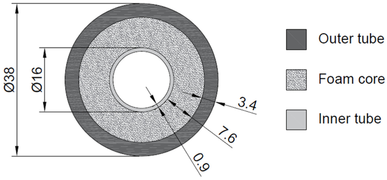
Schematic representation of the hybrid structure.
The materials of the outer and inner tubes are aluminum alloy 6060 T5 and 6061 T6, respectively. The foam core is made of the structural epoxy foam Terocore. The mechanical properties of the above-mentioned materials are summarized in Table 1.
Dimensions and material properties of the hybrid structure. 26

The value herein is the plateau stress of Terocore foam.
Failure is not observed in the experiment.
FE modeling and experimental validation
The FE model of the structure is established using explicit non-linear FE code LS-DYNA. Constant stress solid elements are employed to model the hybrid structure, involving the two cylindrical tubes and the foam core. In order to reduce the effect of mesh size on the accuracy of the model and minimize the computational time, a mesh convergence test was conducted by Bilston et al. 26 The test found that the most suitable element sizes for the outer tube, foam core, and inner tube were 1.5 × 1.5 × 1.5 mm3, 1.25 × 1.25 × 1.25 mm3, and 0.45 × 0.45 × 0.45 mm3, respectively. The power law plasticity material model (*MAT_018) is adopted to represent the aluminum alloys 6060 T5 and 6061 T6. In order to simulate the material behavior of the Terocore foam, the piecewise linear plasticity material model (*MAT_024) is used. The punch and two supports are constructed by thin shell elements and set as rigid bodies (*MAT_020). The velocity of the punch is set as a constant value 7.8 m/s.
The interfaces between the foam and two tubes are modeled using the “tied surface to surface offset” contacts with the friction coefficients 1.0, whereas the “automatic surface to surface smooth” contact is chosen to simulate the contacts between the outer tube and supports/punch. Note that for this kind of contacts, the static and dynamic coefficients of friction are both set to 0.5. The control card of *MAT_ADD_EROSION is applied to simulate the material failure by deleting the elements when they reach a defined criterion. The volumetric strain
Bilston et al. 26 have conducted a three-point bending experiment on the Terocore foam-filled cylindrical tubes. The structure is divided into three layers: the inner layer and the outer layer, which are made up of aluminum alloy, and the middle sandwich, which is a foam material. Therefore, the result of the experiment is capable of validating the accuracy of the FE model established in the study. The deformation patterns of the experiment and the simulation are compared in Figure 3. It can be seen that the deformation modes of simulation agree well with those of the experiment. The slight difference of the foam between simulation and experiment is because the material failure of foam is ignored. As shown in Figure 4, the force–displacement curve of the simulation has fairly good agreement with that of the experiment. It can be found that the difference of PCF, EA, and the maximum displacement with respect to the experiment and simulation is less than 6% (Table 2). To measure the accuracy of simulation to the experiment results, the relative error (RE) can be evaluated as follows

where

Deformation pattern of the hybrid structure 26 : (a) experiment and (b) FE analysis.

Comparisons of force–displacement curves between experiments and FE analysis.
Crashworthiness indicators of experiments and FE analysis.

FE: finite element; PCF: peak crushing force; EA: energy absorption; SEA: specific energy absorption.
Different lateral impacts with three loading positions are considered in this study. A series of different impact locations, that is, the impact at the center point (position 1) and offsetting from the center with 50 mm (position 2) and 90 mm (position 3) are tested as presented in Figure 5. It is obvious that the impact at position 1 is equal to the initial load condition, so the validated FE model is taken to simulate the structure subject to the impact at position 1. The FE models of remaining two load positions are established based on the validated model. The force–displacement curves of three impact positions are compared in Figure 6, and the crashworthiness indicators (i.e. PCF, EA, and SEA) of different lateral impacts are summarized in Table 3.

Schematic representation of the hybrid structures under different loading positions.

Force–displacement curves under different impact positions.
Crashworthiness indicators of the hybrid structures under positions 1, 2, and 3.
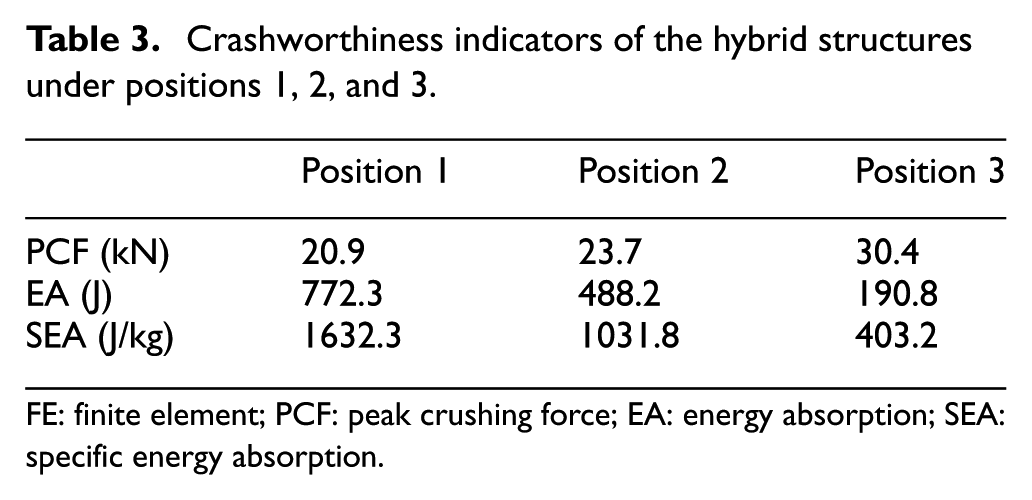
FE: finite element; PCF: peak crushing force; EA: energy absorption; SEA: specific energy absorption.
Parametric study
In this section, a parametric study is carried out to understand the relationship between the design parameters and the bending characteristics of the hybrid structures under various loading positions (i.e. position 1, position 2, and position 3). Four important structural and material parameters are chosen as the independent variables for analysis, including the thicknesses of outer tubes T1, the thicknesses of inner tubes T2, the diameters of inner tubes D2, and the foam densities
Detailed settings of the variables.

Comparisons of PCF with different design parameters
The relationships between the PCF and four variables under different loading positions are plotted in Figure 7. Overall, it is notable that the PCF increases as the impact location offsets from position 1 to position 3. As shown in Figure 7(a), PCF grows dramatically with the increase in T1 under all the loading positions. As shown in Figure 7(b), the value of PCF generally increases as the inner tube thickens, especially under position 3. The change trends of PCF with T2 and

Effects of (a) T1, (b) T2, (c) D2, and (d)
Comparisons of SEA with different design parameters
As shown in Figure 8, all the variables of the structure play vital roles in absorbing the energy. The main features of Figure 8 can be listed as follows:
As shown in Figure 8(a), when the impact occurs in position 1, the SEA of the structure falls off sharply with the increase in T1 when 2.5 mm < T1 < 3.0 mm, but goes up slowly when 3.0 mm < T1 < 4.5 mm. However, the SEA of position 2 changes irregularly when T1 increases. In the case of position 3, the SEA declines intensively as T1 varies from 2.5 to 3.4 mm and tends to be flattened when 3.4 mm < T1 < 4.5 mm. It is observed that the structure with T1 = 2.5 has an outstanding capacity in absorbing energy under position 3. This advantage may probably be caused by the change in the collapse mode of the structure. To visually illustrate the phenomenon, the collapse modes of the structures with T1 = 2.5 mm and T1 = 3.0 mm are compared in Figure 9. As for the structure with T1 = 2.5 mm under lateral impact at position 3, a compression fracture occurs at the top surface of the outer tube initially before a catastrophic failure occurs. Nevertheless, only the catastrophic failure of the outer tube can be observed when T1 > 2.5 mm during the whole load process.
It is demonstrated in Figure 8(b) that under positions 1 and 2, the patterns of SEA variation are fairly irregular, while for position 3, the specific EA ability of the structure is enhanced by increasing T2.
As shown in Figure 8(c), the SEA of position 1 shows the tendency to increase as D2 increases from 10 to 14 mm but declines dramatically when 14 mm <D2 < 20 mm. However, the SEA of position 2 is not sensitive to the variation of D2.
Figure 8(d) displays that the SEA of position 2 clearly shows a descending tendency as
Notably, the EA indicator SEA of the structure is heavily affected by the loading position as shown in Figure 8. On one hand, the structure with higher SEA at the particular loading position does not necessarily perform well when the impact position changes. On the other hand, the relationship between design parameters and SEA values also changes with the change in impact position.

Effects of (a) T1, (b) T2, (c) D2, and (d) ρf on SEA under different impact positions.

Collapse mode of the hybrid structure with (a) T1 = 2.5 mm and (b) T1 = 3.0 mm under position 3.
To conveniently compare the SEA between different impact positions, an integrated indicator of EA (i.e. SEAm) is introduced in this study. Given the specific meaning of the EA indicator, the value of SEAm is defined as the average of SEA under three lateral impacts. The influence of four variables on SEAm is presented in Figure 10. As shown in Figure 10(a), the SEAm drops significantly when 2.5 mm < T1 < 3.4 mm, but reaches a plateau in the region 3.4 mm < T1 < 4.5 mm. The structure with T1 = 2.5 mm shows a huge advantage in absorbing the impact energy. As shown in Figure 10(b), the SEAm monotonously increases when T2 varies from 0.5 to 1.1 mm, and the structure with T2 = 1.5 mm presents the best SEAm performance. It can be observed from Figure 10(c) that there is a small growth of SEAm as D2 increases when 10 mm < D2 < 14 mm. While D2 varies from 14 to 20 mm, the value of SEAm declines considerably. Figure 10(d) depicts that the lower value of

Effects of (a) T1, (b) T2, (c) D2, and (d)
Multi-objective optimization design
Optimization problem formulation
As an EA component, the hybrid structure is supposed to absorb as much energy as possible per unit mass. Besides, the excessive high-impact force may lead to severe structural deformation and occupant injury in the traffic collision. Therefore, SEA and PCF are defined as the objective functions to be maximized and minimized, respectively. The parameters discussed in section “Parametric study” are chosen as variables herein, including the thickness of outer tube T1, the thickness of inner tube T1, the diameter of the inner tube D2, and the foam density
Ignoring the variability of impact location, the multi-objective optimization design under SLC only focuses on the typical three-point bending (i.e. position 1) since it is the most commonly used loading condition. The optimization problem under SLC can be expressed mathematically as follows

Taking into account the multiple lateral impacts with variable loading positions, the original objectives involving SEA and PCF should be adjusted correspondingly. As mentioned in section “Parametric study,” the EA indictor SEA under MLC has been set to SEAm. Another indicator PCF is modified to PCFm under MLC with reference to its specific meaning. SEAm and PCFm can be calculated as follows

where SEA1, SEA2, and SEA3 are the SEAs of the hybrid structure under three loading positions, respectively. Similarly, PCF1, PCF2, and PCF3 denote the PCF under each position. Thus, the corresponding optimization problem under MLC can be expressed as follows

Design of experiment
In order to minimize the effect of sampling on the accuracy of surrogate model, the design of experiments (DOE) method is often adopted to generate design samples. 28 The most commonly used DOE methods include full factorial design, orthogonal design, and central composite design, Latin hypercube sampling (LHS) and OLHS. 29 Taking advantages of providing space-filling and uniformly distributed sampling points in the design region efficiently, 30 the OLHS is employed to construct the surrogate model in the following optimizations.
Surrogate models
Surrogate model techniques have been widely employed to solve the engineering optimization problems owing to the advantages of replacing the complex implicit systems with mathematical models. 31
As one of the most extensively used surrogate model methods, RBF has shown overall advantages on accuracies, robustness, sample size, problem types, efficiency, and simplicity. RBF, which was originally developed for scattered multivariate data interpolation, employs a series of basis functions that are symmetric and centered at each sample points. 32 A general form of RBF can be written as follows

where S is the number of sample points,

where c is a shape function variable between 0.2 and 3. As shown in equation (6), it can be found that an RBF model is a linear combination of S RBFs with an added polynomial function.
To assess the accuracies of the established RBF models, three numerical estimators, namely, R-square (R2), root mean square error (RMSE), and maximum absolute relative error (MARE), are introduced as follows


where m is the number of validation points, yi is the true response,
Optimization algorithm
In the multi-objective optimization problem, a multi-objective optimization algorithm is required to make trade-offs between two or more conflicting objectives and generate a set of the non-dominated optimal solutions called the Pareto frontier. 33 Compared to other multi-objective optimization algorithms, such as non-dominated sorting genetic algorithms (NSGA) and Pareto archived evolution strategy (PEAS), the MOPSO34,35 has superiorities of its fast convergence and well-distributed Pareto frontier. 36 In this study, MOPSO is implemented to optimize the hybrid structures under different positions.
Optimization procedure
The flow chart of multi-objective optimization problem under different load cases is presented in Figure 11. First, 50 initial samples are generated with a homogeneous distribution in the interior of the design space by OLHS. Moreover, 10 validation points are produced for the purpose of verifying the accuracy of the surrogate models. Second, the FE models of the initial samples and validation points are established and analyzed under three impact positions. Based on the responses of objectives, the RBF models were constructed. Since the prediction accuracy of the surrogate models herein is not enough, additional 14 sampling points are chosen to improve the accuracy of the RBF models. The error estimators of the rebuilt RBF models are summarized in Table 5. It can be found that the models are capable of the following optimizations with sufficient accuracies. Finally, the adequate Pareto solutions of the optimizations under different load cases are obtained by MOPSO after 100 iterations.

Flow chart of multi-objective optimization under SLC and MLC.
Accuracies of the RBF surrogate models.
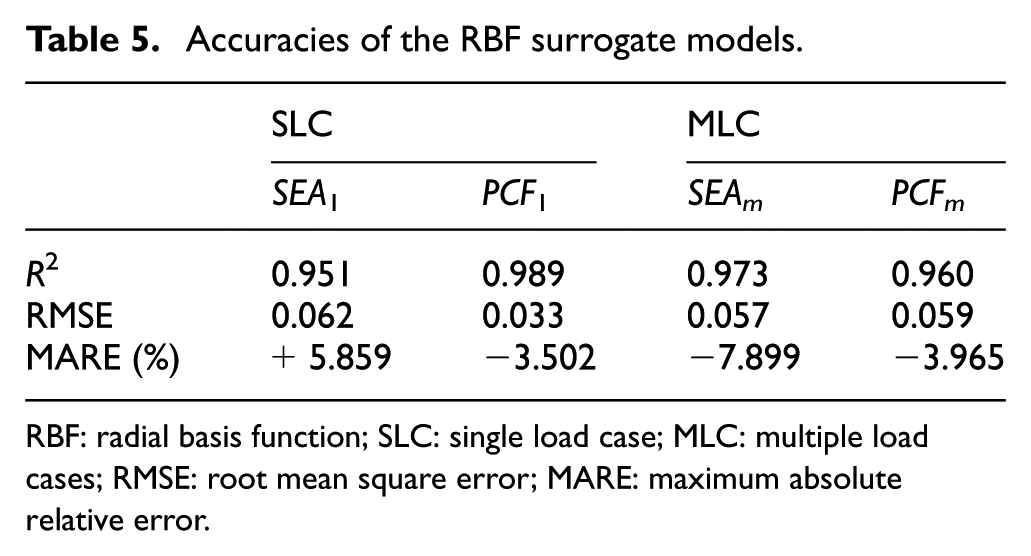
RBF: radial basis function; SLC: single load case; MLC: multiple load cases; RMSE: root mean square error; MARE: maximum absolute relative error.
Results and discussion
Two Pareto fronts of the PCF against SEA for the hybrid structures under SLC and MLC are plotted in Figure 12. First of all, the Pareto fronts directly depict that the two objectives PCF and SEA are conflicting with each other in all load cases. In other words, increase in SEA may lead to increase in PCF, which is undesirable in the real-world application.

Pareto fronts of the hybrid structures under SLC and MLC.
Obviously, the Pareto fronts of different load cases have no overlap region. The Pareto fronts of SLC and MLC optimization locate in the left and right parts of the graph, respectively. It is because the loading position has a huge influence on the bending resistance of the structures as mentioned in section “Parametric study.” The great gap between the two curves reveals that the optimal hybrid under a specific impact position does not necessarily satisfy the design demands of the other load cases and also verifies the importance of applying the MLC in the optimization.
Although the Pareto fronts provide the designers with numerous available schemes to choose, the best compromised design point must be selected from the Pareto solutions in terms of the specific design requirements. For example, emphasis on the occupant safety may lead to the sacrifice of the EA capacity. In contrast, if the designers pay more attention to the EA capacity of the structure, the design schemes with relatively high SEA should be considered first. Sun et al. 37 proposed a method called the minimum distance selection method (TMDSM) in order to determine a most satisfactory solution (namely, a knee point) from the Pareto sets. TMDSM provides a perfect way to make a balance between the conflicting objectives. Therefore, the TMDSM is taken to choose the optimal designs under SLC and MLC and the selected points are marked in Figure 12. The detailed parameters of the optimal designs under two different load cases are listed in Table 6. In the meantime, the FE models based on the optimal designs are established and tested. The corresponding responses predicted by RBF surrogate models and obtained by FE models are given in Table 7. It can be seen that the errors between the FE results and the corresponding predictions are less than 5%, demonstrating that the accuracies of RBF models for SLC and MLC are acceptable. As shown in Table 7, the optimization results also show that SEA1 and SEAm are reinforced by 57.174% and 44.457%, respectively. Compared to the original design, PCF1 and PCFm of optimal designs are reduced by 25.755% and 16.235%, respectively. Hence, the optimized hybrid structures can be regarded as the best configurations for energy absorption under SLC and MLC, respectively.
Optimal design parameters for the hybrid structures under SLC and MLC.

SLC: single load case; MLC: multiple load cases.
Results of optimal designs under SLC and MLC.
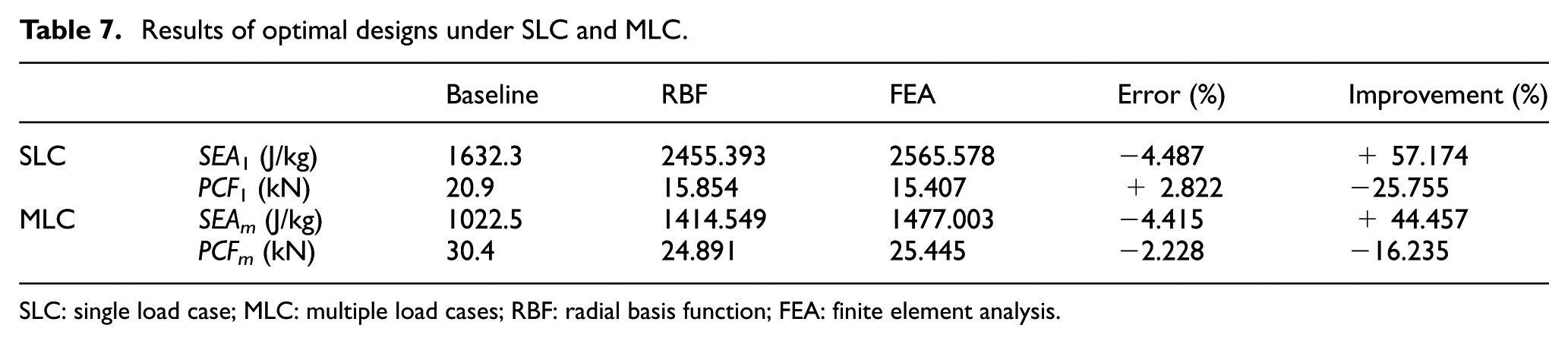
SLC: single load case; MLC: multiple load cases; RBF: radial basis function; FEA: finite element analysis.
Conclusion
In this article, the bending resistance of the Terocore foam-filled double cylindrical hybrid structures is investigated by simulation analysis and optimization design. Unlike most of the existing research works that sorely concentrated on the lateral impact at mid-span, different impact positions are taken into consideration in the study. A parametric analysis is conducted to discover the influences on SEA and PCF with respect to the thicknesses of outer and inner tubes, the diameters of inner tubes, as well as the foam densities. Furthermore, the hybrid structure is optimized under SLC and MLC using a combination method of OLHS, RBF model, and MOPSO. The main conclusions from the investigation can be listed as follows:
The loading position has a significant effect on the crashworthiness indicators SEA and PCF, resulting in the optimal design which highly depends upon the particular load case. Therefore, the optimization result considering different impact positions is more applicable and practical than that under a specific loading position.
The bending behavior of the hybrid structure is strongly influenced by several design parameters under all loading positions, including thicknesses of inner and outer tubes, the diameter of inner tube, and the foam density. It calls for the optimizations to improve the bending resistance of the structures under SLC and MLC.
The optimal structure under SLC improves the SEA value by 57.174% and reduces the PCF by 25.755% than the original one. The optimization design for MLC shows a 44.457% increase in SEAm and a 16.235% reduction in PCFm. For that reason, an appropriate design of the hybrid structure can be highly recommended as an efficient EA application to protect vehicle occupants under lateral impacts.
This article is restricted to the double cylindrical tubes filled with Terocore foam subjected to three-point bending. More EA structures with various parameters, materials, cross sections, as well as loading conditions still need to be fully explored in the future.
Footnotes
Handling Editor: MA Hariri-Ardebili
Declaration of conflicting interests
The author(s) declared no potential conflicts of interest with respect to the research, authorship, and/or publication of this article.
Funding
The author(s) disclosed receipt of the following financial support for the research, authorship, and/or publication of this article: This project is supported by National Natural Science Foundation of China (51505115).