
Abstract
A three-parameter suspension system is often used for vibration isolation of sensitive devices especially in a space industry. This article describes the three-parameter suspension system with magnetorheological valve controlled by Skyhook algorithm. Simulations of such systems showed promising results. They, however, showed that the suspension performance is strongly influenced by magnetorheological valve response time. Results from simulations proved that the semiactive control of such system with response time of magnetorheological damper up to 4 ms outperforms any passive setting. The simulations were verified by an experiment on suspension system with magnetorheological valve with response time between 3.5 and 4.1 ms controlled by a Skyhook algorithm. Although the control algorithm was slightly modified in order to prevent instabilities of control loop caused by signal noise, the results from the experiment showed the same trends like the simulations.
Introduction
A three-parameter suspension system consists of three basic elements which can be tuned during designing of suspension system for a given payload

Model of the three-parameter system with MR damper.
Active systems, however, need a lot of energy for their operation and complex control. From this point of view, semiactive systems with magnetorheological (MR) damper can be advantageous. Such systems can control the damping force by electric current connected to the coil of MR valve. According to the frequency of damper current change, the control can be very slow—adaptive systems—or semiactive; the damper F-v dependency is changed faster than vibration frequencies which should be controlled by damper. 6
Many semiactive algorithms have already been described. Among the most famous belongs Skyhook, which was first described by Karnopp et al. 7 Since then, the simulations of Skyhook controlled systems has been described in many fields. Ahmadian et al. 8 and Dong et al. 9 compared various semiactive algorithms for vehicle suspension. Choi et al. 10 described the use of Skyhook algorithm for vibration isolation for ground support equipment of mobile launch platforms. Jean et al. 11 evaluated the use of MR damper for launcher payload isolator controlled by the Skyhook algorithm.
The use of MR technology for semiactive suspension systems has, however, its limitations which influence the suspension performance:
Dynamic range: It is a rate of maximal force to minimal force for a given piston velocity. Yang et al. 12 showed a dependency of the width to length rate of the gap on dynamic range. The dynamic range is also dependent on maximum magnetic field in the gap.13,14 Cvek et al. 15 described the influence of MR fluid composition on dynamic range. Roupec et al. 16 described a decrease of dynamic range in dependence on MR fluid degradation level. Goldasz and Sapinski 17 created complex model of MR damper which shows the dependency of dynamic range on mechanical construction.
Response time of MR valve: It is obtained from a response of the damper force on the (voltage) step of command signal to the current controller. In the majority of cases, it is described as the duration between the moment of step of control signal and achieving the 63.2% of settled force between activated and non-activated state. 18 The response time is often neglected in simulations, 19 but in Strecker et al., 20 it was proven that the response time of MR damper has fatal impact on the performance of real suspension controlled by semiactive algorithms. The overall response time of the whole MR damper is caused by couple of phenomena:
Response time of MR fluid (measured by Goncalves et al. 18 ): They measured the MR fluid response time between 0.45 and 0.6 ms.
Inductance of MR damper coil: The inductance of the coil produces a non-zero response time of the electric current when power source is connected to the terminals. Yang et al. 12 and Koo et al. 21 experimentally proved that the use of current controller instead of the voltage power source significantly reduces the rise time of the current to the desired value.
Eddy currents in the magnetic circuit: Guan et al. 22 noticed that the MR damper force rise, after the step of electric current to the coil, is much longer compared to the course of electric current. This delay was explained as a result of eddy currents, which are generated during fast changes of electric current in the coil. Eddy currents can be eliminated if the magnetic circuit is made of material with high electric resistivity. The example of material with high electric resistivity and quite good magnetic properties is ferrites. Maas and Güth 23 used ferrites for MR clutch for the first time. Strecker et al. 20 constructed an MR damper with ferrite piston and measured its force response time. By this approach, the response time shorter than 2 ms was achieved.
The aim of the work was to evaluate a quality of the three-parameter suspension system with fast MR valve controlled by Skyhook algorithm in comparison with passive system. The sensitivity of suspension performance on response time of MR valve was examined in virtual model and verified by experiment. The experimental system is simplified 1/8 model of semiactive suspension system for Vega space vehicle based on Stewart’s platform. The experimental system was used in order to evaluate the vibration suppression using semiactive Skyhook algorithm in longitudinal axis. The suitable natural frequency of the system was determined from Vega space vehicle user’s manual. 24 The scale was 1:1 for the smallest payload 400 kg.
Methods
The quality of a suspension system was determined from transfer ratios of a sprung mass acceleration to a base acceleration. The suspension system was excited by logarithmic sweep. The transfer ratios were evaluated for passive and Skyhook controlled MR damper and various settings of MR damper parameters (electric current, response time of the damper). The simulation model was verified by measurement on a real system for several settings. In order to eliminate non-linearities (Coulomb’s friction caused by seals) in force–velocity dependency of telescopic dampers with piston, the bellows unit together with MR valve were used instead. The bellows unit makes MR oil to flow through the MR valve which causes the damping force. These two units hence form F-v dependency like ideal MR damper without friction forces. The construction of bellows unit also determines the stiffness
System model
A system model according to Figure 1 was designed in MATLAB. This model is based on Newton’s laws of motion


where


And the damping force
Values of parametric system.

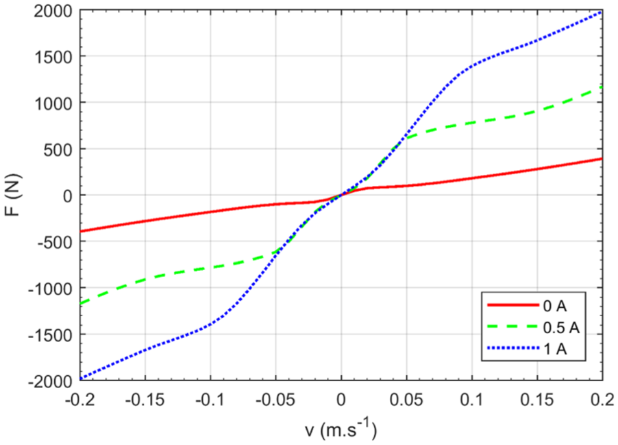
F-v dependencies of MR valve.
The mass
The damping force
Dynamic behavior of the damping force was approximated as the first-order dynamic system. Such system output (force)

where the parameter
Algorithm principle
Algorithm “On/Off Skyhook” was used for simulation and experiment. The rule for turning on/off the current

The rule for turning off the current to the MR valve is according to equation (8)

Experiment
An experimental setup is in Figures 3 and 4. The natural frequency of the system was tuned to 11 Hz. This frequency was chosen as a suitable natural frequency for Vega spacecraft.
24
The experimental setup consisted of hydraulic pulsator which excited the suspension system: the bellows unit with volumetric stiffness

Experimental three-parameter suspension system.

Schematic cross-section of the three-parameter suspension system.
The MR valve (Figure 5) was designed with three coils in order to achieve high dynamic range. The gap was 0.6 mm. The MR valve was filled with MR fluid LORD MRF-132DG. Important parts of MR valve magnetic circuit (rings, rod) were made of ferrite material which has low electric conductivity, thus eliminates eddy currents. The outer cylinder was made of S235JRG2 steel. A hydraulic, magneto-static model and measurements of response time of the MR valve are described in Kubík et al.
26
The time response was evaluated from a measurement in a hydraulic pulsator Inova, which was generating harmonic dependency of position on time with stroke 2.5 mm. In the middle of the stroke (measured by linear variable differential transformer [LVDT] sensor), the electric current (measured by current clamps Fluke i30s) to the MR valve coil is turned on, which causes the rapid increase in force (measured by load cell Interface 1730ACK-50kN) (see Figure 6). The time response T (Figure 7) is the time needed for reaching 63.2% of force between non-activated and activated state. More detailed description of the measurement and time responses at different piston velocities can be found in Kubík et al.
26
The coils of MR valve were connected to the current controller of our design. The controller enables to reduce the response time of the electric current on control signal up to 1 ms. The reduction of the current response time is possible by increasing the voltage on the coil until the desired current is reached (voltage overdrive). The current controller with overdrive 60 V was used for experiments. Therefore, the overall response time of the MR valve force on control signal was measured between 3.5 and 4.1 ms in dependence on relative velocity and slope of electric current to the coil (rising, falling). The bellows unit was chosen instead of the double-ended hydraulic tube in order to eliminate Coulomb’s friction and hence to keep high dynamic control range of MR valve forces. The base was excited by sweep signal, 5 to 50 Hz, with base acceleration amplitude

Cross-section of MR valve

Measurement of MR damper response time.

Measurement of MR damper response time in detail.
Figure 8 shows the block scheme of control loop. Signals representing the acceleration of sprung mass

Scheme of measurement.
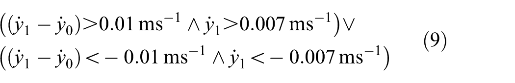
Because of chattering caused by noise in measured signals, a hysteresis was implemented for the turning on rule of Skyhook algorithm. The hysteresis margins, in equation (9),
Results and discussion
Simulations
Figure 9 shows the comparison of simulated acceleration ratios between passive settings and Skyhook controlled system. The passive system with MR valve without current exhibits the best performance on frequencies above 20 Hz, but there is a high peak at resonance frequency. The system with constant current of 1 A to MR valve is almost critically damped (critical damping is
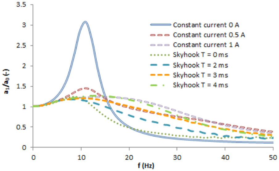
Simulated acceleration transfer ratios.
Experiment
The results from measurement on a real system are in Figure 10. The acceleration transfer ratios for constant passive mode (constant current: 0, 0.5, and 1 A) exhibit the same trends like simulated transfer ratios. Figure 10 also shows the acceleration transfer ratio for Skyhook controlled system. The response time of MR valve was measured between 3.6 ms for force drop and 4.1 ms for force rise. 26 These values were, however, affected by control limits of hydraulic pulsator on which the response times were measured, and hence the real response times will be slightly shorter. The vibration attenuation of Skyhook controlled system at low frequencies is worse than in model—there is a small peak at resonance frequency. On the contrary, the performance on higher frequencies is better than in model. The differences between simulations and experimental results are caused by above-mentioned uncertainty of response time measurement and by differences in switching of the current to the coil shown in Figure 11.
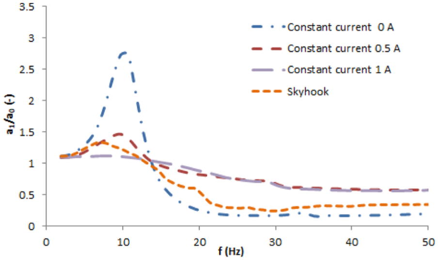
Measured acceleration transfer ratios.
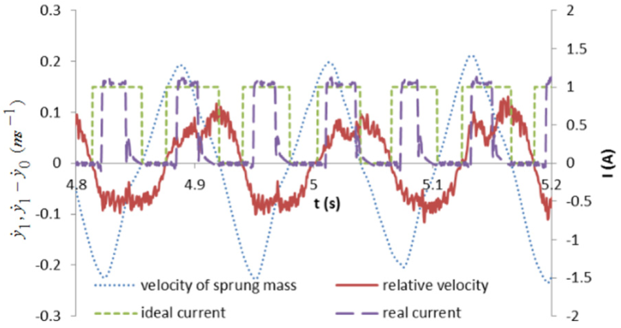
Courses of algorithm input variables and generated ideal and real control signal.
The plot shows the variable relative velocity and sprung mass velocity which are needed for the calculation of switching the current to the MR valve according to the Skyhook algorithm. Because both of these variables are not measured directly, but filtered by IIR filters and calculated by integration (velocity of sprung mass) and derivation (relative velocity), there are some phase shifts and delays in signal needed for calculation of rule described by equations (8 and 9) which determines Arduino output. Therefore, the real current (dashed line) is not turned on and off exactly in the same moments like in simulation (ideal current). This also causes that at frequencies above 20 Hz, the current into MR valve is most of the time turned off, and hence the transfer ratio of Skyhook algorithm is close to the transfer ratio of passive setting with the current 0 A. Figure 11 is obtained from post-processed signals, where all the delays and phase shifts are compensated directly by Dewesoft software.
Conclusion
The simulations showed that three-parameter system controlled by Skyhook algorithm can outperform any of passive variants. The performance of such semiactive suspension system is, however, very sensitive on the response time of MR valve. The simulations show that for the efficient control of the system with resonance frequency tuned to 11 Hz (and dynamic range around 8), the response time of MR valve should be up to 4 ms. The shorter the response time of MR valve, the better the performance of the suspension. The response time of MR valve used in experiments was between 3.5 and 4.1 ms, which was not sufficient for large improvement on resonance frequency. The hysteresis margins for the turning on rule can, however, secure good vibration attenuation at higher frequencies. As a whole, Skyhook controlled system with MR valve with response time up to 4.1 ms can secure good vibration attenuation in the whole frequency range. No passive setting can combine as good vibration attenuation as Skyhook controlled system in the whole frequency range. At low frequencies, the Skyhook controlled system behaves better than passive system tuned to approximately half of critical damping, while at high frequencies, the Skyhook controlled system can be compared to the passive system with approximately 1/7 of critical damping. The trends of experimental results agree with simulations although the performance of suspension system controlled by Skyhook semiactive algorithm is for frequencies close to the resonance frequency of the system worse than in simulations. The reasons are the slow response time of the MR valve and the signal delays caused by slow control loop, phase shifts in calculated signals caused by IIR filters, and hysteresis in control algorithm running in Arduino which was necessary in order to prevent chattering. As a result, the current is not turned on and off exactly according to the simulations. The performance of the semiactive suspension system should be improved if the response time of the MR valve is shorter and the control loop frequency is increased, and also if better filters, especially for calculating the relative piston velocity, are used. Kalman or complementary filters, described in Higgins, 27 should be the solution. The long response time of MR valve was probably caused by eddy currents generated in the outer cylinder (made of steel) during fast changes of the electric current. Reduction of the response time up to 1 ms (response time of MR fluid) can be expected if the outer cylinder is made of electrically non-conductive material. The use of MR valve with such low response time in Skyhook controlled suspension system promises better vibration isolation than any passive setting in the whole frequency range.
Footnotes
Acknowledgements
The authors appreciate very much a kind sponsorship of numerous agencies, which granted as much as they could.
Handling Editor: Elsa de Sa Caetano
Declaration of conflicting interests
The author(s) declared no potential conflicts of interest with respect to the research, authorship, and/or publication of this article.
Funding
The author(s) disclosed receipt of the following financial support for the research, authorship, and/or publication of this article: The research leading to these results has received funding from GAČR 17-10660J, GAČR 17-26162S, and FSI-S-17-4428.