
Abstract
A light-emitting diode chip sorting machine, which operates at high frequencies, exhibits reciprocating motion with multiple degrees of freedom and is characterized by quick starts and stops over a short range at a high frequency. The stiffness sensitivity of the chip sorter directly influences the positional accuracy of the sorting arm. However, existing experimental modal analysis methods cannot effectively identify the structural stiffness sensitivity under high-speed operation conditions. In this article, a method based on the modal mass distribution matrix is used to analyze the stiffness sensitivity of the sorting arm system. This method retrieves the modal parameters by modal analysis, after which the modal mass distribution matrix is obtained. The size of each element in the column of the matrix represents the energy distribution and stiffness sensitivity of the system under the mode. The stiffness-sensitive components of the sorting arm machine are accurately and quickly identified, thereby providing the guiding principle and basis for the dynamic optimization of the sorting arm mechanism.
Introduction
Mechanical structures are complex, as they are composed of a number of elastomeric parts. Several studies have shown that the stiffness and mass matrix of a system and the dynamics of the mechanism vary as the positions of the various parts change.1–3 Furthermore, there is a strong correlation between the stiffness of a mechanical system and both the end position and the operating parameters.4,5 During the operation of the mechanism, the movement transmission between parts exhibits hysteresis, which makes it difficult to accurately model changes in the stiffness damping of movable and non-movable joints, such as bearings and guide rails. 6 In addition, the existing methods such as multi-body theory and the finite element method (FEM) employed to theoretically model the dynamic characteristics of machine structures have not yet reached the accuracy required for investigating the dynamic characteristics of mechanical structures. Therefore, research on the dynamic characteristics of machine structures under operating conditions needs to be based on experimental testing and measurement.7–9
I Zaghbani and V Songmene 10 studied the effects of the high-speed structure on the dynamic characteristics of the machine tool at two locations, that is, the part of the tool away from the workpiece and the part close to the workpiece; they also noted that changes in the spindle position have certain influences on the dynamic characteristics. To study the dynamics of cutting tips at different working positions, MM Sadek and WA Knight 3 conducted a modal experiment and noted that the frequency response function (FRF) of the tool tip point will change throughout the working space. Much of the research conducted on kinetic properties has been performed with regard to the tool tip. However, SA Tobias and W Fishwick 11 emphasized that studies on mechanical structural dynamics should not focus on a single component; rather, the entire structure must be taken into account while considering the influences of boundary conditions between the movable and non-movable parts of the system, and thus, the modal parameters (i.e. the natural frequency, damping ratio, and mode shape) of the structural component should be studied based on this research. In addition, C Brecher and colleagues 12 noted that the dynamic analysis of machine tools is concerned entirely about the tool spindle as the most sensitive component. However, both the speed and the position of a component are related to the dynamic characteristics of the machine tool. Therefore, the structural dynamic characteristics of the working space will constitute an important research direction in the future.
At present, the primary method utilized to identify structural modal parameters is experimental modal analysis (EMA). 13 The EMA method uses artificial excitation to obtain the FRF of the structure by measuring the excitation force and vibration response, following which the modal parameters can be recognized.14,15 However, because the EMA method requires an accurate measurement of the FRF between the excitation force and the vibration response, this method can be applied only under the condition that the structure is stationary; accordingly, the modal parameters in the operational state cannot be identified.
Compared with the EMA method, the operational modal analysis (OMA) method uses only the vibration response signal of the structure in an operational state to recognize the modal parameters, and this technique is capable of recognizing the dynamic characteristics of a structure under different working states. 16 Therefore, the OMA method has increasingly attracted widespread attention, and it continues to be applied to the development of a variety of identification methods.17–23 The main feature of this method is that it can extract the free response signal from the vibration signal under working conditions and then identify the modal parameters. 24 Accelerometers are commonly used with the OMA method to obtain the structural vibration response, 25 and they are typically used for large mechanical structures, such as machine tools; consequently, the sensor mass can be neglected. For lightweight structures operating under high frequencies, the accelerometer quality cannot be neglected, because a poor sensor quality would yield additional mass effects. As a result, it is often difficult to identify the modal parameters of lightweight structures operating under high frequencies.
Accordingly, the main goals of this study are (1) to establish a method to identify the stiffness-sensitive parts of a rotary arm structure and (2) to analyze the influences of stiffness-sensitive parts on the vibration characteristics of the sorting arm mechanism. The results of this investigation will provide the guiding principle and basis for the dynamic optimization of a sorting arm mechanism.
The remainder of this article is organized as follows. In section “Displacement vibration of a sorting arm under an inertial impact,” the displacement vibration of a sorting arm on a light-emitting diode (LED) chip sorting machine is investigated under an inertial impact. Section “Stiffness sensitivity analysis based on the modal mass distribution matrix” presents a sensitivity analysis of the dynamic stiffness based on the modal mass distribution matrix. Section “Simulation verification of multiple DOFs” presents a simulation verification of multiple degrees of freedom (DOFs), and section “Stiffness sensitivity analysis of the rotation arm structure” presents a dynamic stiffness sensitivity analysis of the rotation arm structure. Finally, the results are summarized in the conclusion.
Displacement vibration of a sorting arm under an inertial impact
Figure 1(a) presents the experimental platform: a high-speed LED chip sorting machine (model: DH-LS436LED). Its motion precision is on the micron level, and the acceleration of the rotary arm during movement reaches 15g. The reciprocating frequency of the arm is greater than 15 Hz, and the chip picking time is 10 ms. The double sorting arm system rotates 180° back and forth; when one arm takes a chip, the other arm places the chip. The two worktables move in the horizontal plane to ensure the precise positioning of the chips. A substantial centrifugal force is exerted when the rotary arm is operating at high speeds, and thus, accelerometers cannot be attached. Thus, this article uses non-contact displacement sensors instead of accelerometers. Figure 1(b) presents the arrangement of the laser displacement sensors. Figure 1(c) and (d) presents motion process and the sorting cycle of chips, respectively.
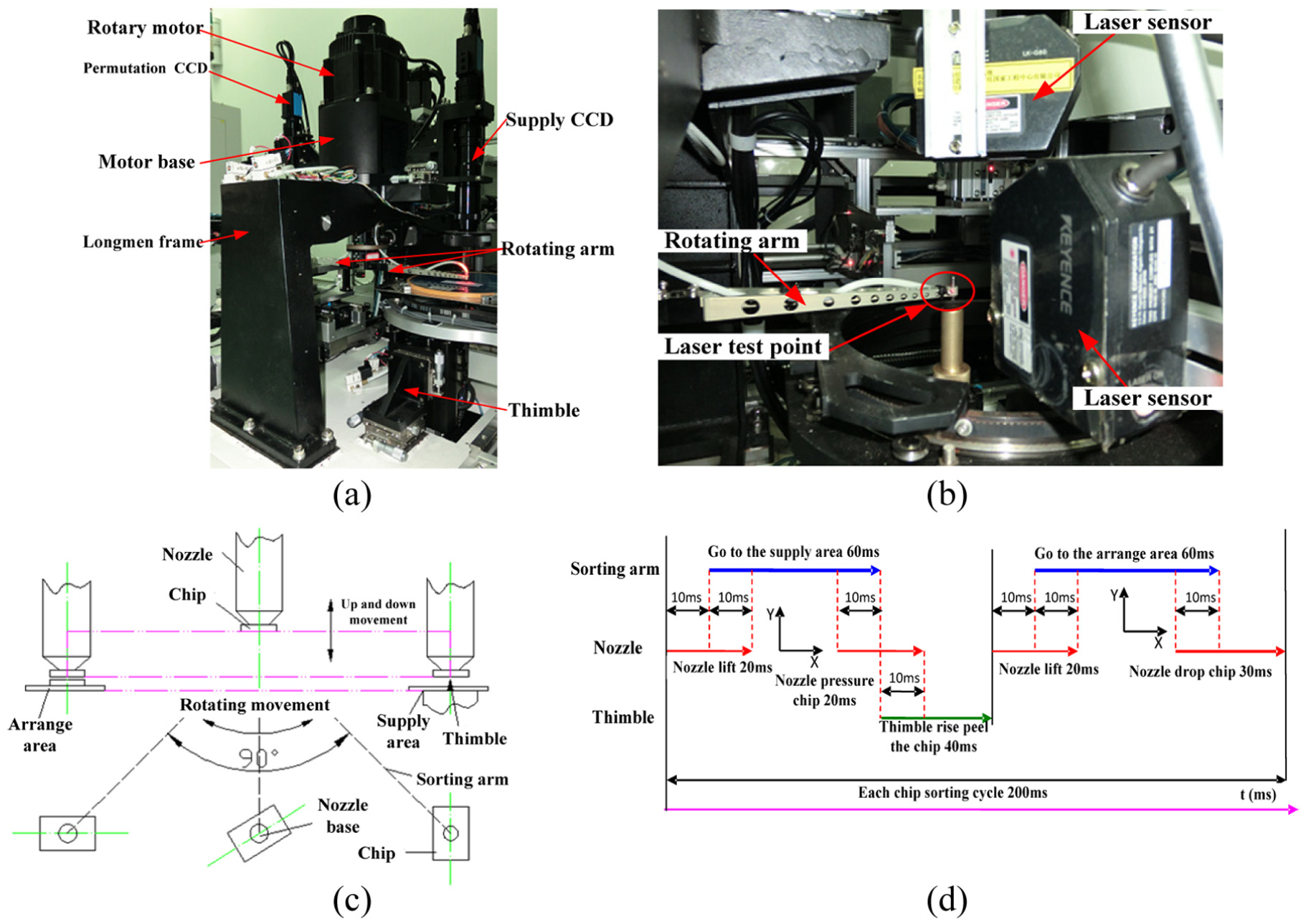
(a) Sorting arm of the LED chip sorting machine, (b) vibration response experiment using a laser sensor, (c) motion process diagram, and (d) the sorting cycle of chips.
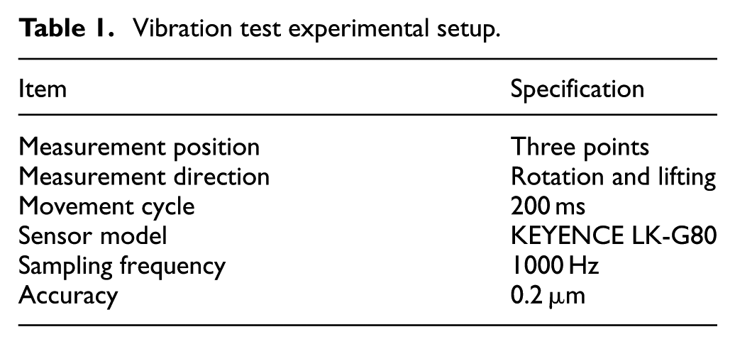
Figure 1(b) displays the experimental sorting arm system. The vibration of the working position in two directions is measured by two laser displacement sensors. One of the measuring points is located at the side end of the sorting arm; this sensor recognizes the vibration characteristics in the direction of rotation. The other sensor is placed on the upper surface at the end of the rotating arm; this sensor detects the vertical vibration characteristics. The specific experimental conditions are shown in Table 1.
Vibration test experimental setup.
Because the structure of the double sorting arm system is symmetrical, Figure 2 shows the vibration displacement curve of only one sorting arm end. Evidently, the end of the sorting arm exhibits a larger vibration than the other parts of the arm. In addition, the two sorting arms reach displacements of 128 and 50 μm, and the stability time of the sorting arm mechanism is 20 ms. Thus, the high-frequency reciprocating operation has an obvious impact on the dynamic characteristics of the sorting arm mechanism.

Vibration linear displacement of the sorting arm in the rotation direction.
The actual measured displacements of the end of the sorting arm in the direction of rotation and the vertical direction exceed the design requirements (i.e. ±5 μm). As shown in Figure 2, during the period of contact with the chip, the amplitude of the vibration displacement at the end of the sorting arm reaches 16 μm.
Further analysis of the vibration displacement curve shows that the measured displacement in the direction of rotation increases during vertical movement. Obviously, during the process of picking up and placing chips, the vertical movement of the sorting arm causes the arm to vibrate in the direction of rotation. However, the vibration in the direction of rotation is the primary factor affecting the operational precision.
The measured vibration displacement of the sorting arm under an inertial impact was analyzed, and the following conclusions were obtained:
Because of the inertial shock caused by the high-frequency reciprocating motion, the sorting arm exhibits a transmission gap and an inertial delay in addition to elastic deformation, all of which cause a time delay to appear in the displacement of the sorting arm.
The high-frequency reciprocating movement has a definite influence on the dynamic characteristics of the sorting arm, and the vibration response of the sorting arm is related to the motion of the arm.
Stiffness sensitivity analysis based on the modal mass distribution matrix
A sensitivity analysis of the dynamic stiffness based on the generalized modal mass is performed to obtain the modal parameters, including the natural frequency, modal mass, and mode shape vector, for a sorting arm model. The generalized modal mass distribution matrix expresses the modal parameters of each component uniformly such that each element in a column of the generalized modal mass matrix represents the distribution characteristics of the DOF of each part, and the size of the column vector indicates the modal stiffness sensitivity of that component.
Accordingly, the stiffness sensitivity of the sorting arm mechanism is determined based on the generalized modal mass matrix. Then, the relative stiffness sensitivities of specific parts are obtained. Finally, the stiffness-sensitive components of the sorting arm are identified. The n-DOF homogeneous dynamic equation without damping can be written as follows

where [M] and [K] are the mass and stiffness matrices, respectively, which are real symmetric matrices, and

When


Substituting

The ith modal mass is composed of
The mass distribution of each component within the sorting arm is not uniform because the materials composing the parts are different. If the kinetic energy of a certain DOF is larger, the component mass is also relatively large, and thus, the amplitude of the vibration mode component is smaller. Similarly, if the kinetic energy of a DOF is smaller, its mass is also relatively small, and thus, the amplitude of the vibration mode component is likely to be larger.
For each part of the sorting arm, compared with the kinetic energy of a DOF, a larger amplitude of the modal shape vector at each DOF will lead to a greater impact on the chip sorting positioning accuracy during high-frequency operation. Therefore, the amplitude of the vibration mode shape vector at each DOF can better reflect the local sensitivity of each component.
The mass of each DOF is normalized, after which the generalized mass matrix
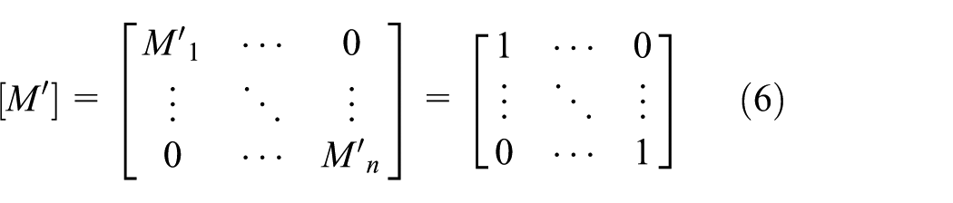
Substituting

The modal mass of the ith mode
The spatial distribution of the generalized modal mass can be rearranged in the form of a vector. Each element of the vector is the corresponding square of
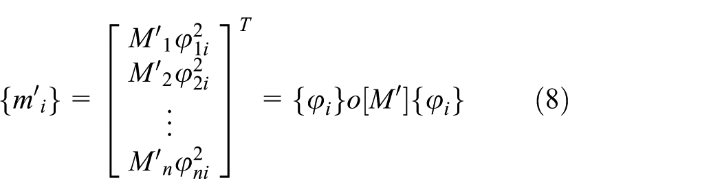
where o is an overlapping multiplier that multiplies the corresponding elements of two matrices, and the result is the corresponding element of the matrix. The generalized modal mass distribution vectors of each mode constitute the modal mass distribution matrix; therefore, the generalized modal mass spatial distribution matrix can be expressed as follows

The matrix
If the generalized kinetic energy of a certain mode is highly concentrated in a local range, the component of the sorting arm system corresponding to this range can be considered a sensitive part in this mode.
Simulation verification of multiple DOFs
To verify the sensitivity analysis presented in the previous section, a spring oscillator system with multiple DOFs is constructed, as shown in Figure 3. Two situations are designed, namely, a system containing stiffness-sensitive parts and a system that does not contain stiffness-sensitive parts.

Spring oscillator system.
The size of each mass element and the stiffness of the spring are established, and the modal vector is obtained through simulation. The spring oscillator system is identified by the proposed stiffness-sensitive component identification method.
A comparison of the results identified in these two cases proves that the proposed method is correct if the identified stiffness sensitivity in the system is in accordance with the established stiffness values. The number of DOFs of this model is set to 30. Assume that the model has no damping, that is,
State A: no stiffness-sensitive parts.
The system stiffness values are expressed as
State B: stiffness-sensitive parts.
To highlight the stiffness-sensitive parts more directly, the stiffness of the system is expressed as
Because the spring stiffness values K10 (between M9 and M10) and K20 (between M19 and M20) are much smaller than those between other parts in the system, the corresponding DOFs of the spring should represent the stiffness-sensitive parts in the system. The mass matrix [M] and stiffness matrix [K] of the system are expressed as follows
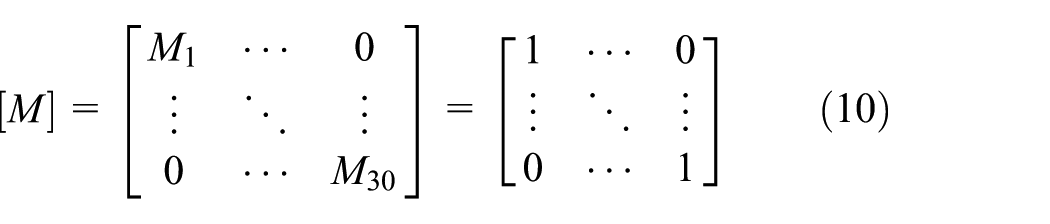
The dynamic equation of the system is given as follows

where

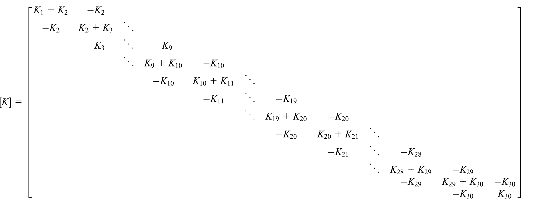
The matrices [K] and [M] of States A and B are substituted into equation (12), and then, the natural frequency
The first modal parameters of States A and B.
Similarly, the parameters of the second through the sixth modes of the system in State A and State B are also obtained. Figure 4 presents each modal distribution of the generalized modal mass distribution vector at each DOF. Figure 4(a)–(f) shows the distributions of the first six modes under the two states, namely, States A and B; the blue curve represents the distribution vector under State A, and the red curve represents the distribution vector under State B.

The modes under States A and B: (a) Mode 1; (b) Mode 2; (c) Mode 3; (d) Mode 4; (e) Mode 5; and (f) Mode 6 (Blue lines: State A. Red lines: State B).
As shown in Figure 4, when there are no stiffness-sensitive parts (State A) in the system, the overall distributions of the modal mass distribution vectors at different DOFs exhibit a sinusoidal law that is stable with no mutations. In contrast, when there are stiffness-sensitive parts in the system (State B), the overall distributions exhibit obvious mutations, and the abrupt position constitutes the stiffness-sensitive component of the system.
To summarize, the results of the stiffness sensitivity analysis via the use of the generalized modal mass distribution matrix and the use of previous stiffness settings are in good agreement. The simulation results therefore demonstrate the validity of the proposed method.
Stiffness sensitivity analysis of the rotation arm structure
The scaled modal shape vectors and the scaled modal shape matrix can be computed via EMA. When equation (3) is post-multiplied by the inverse of the scaled modal shape matrix and pre-multiplied by the inverse of the transposed scaled modal shape matrix, the following can be obtained

If the scaled modal shape matrix [φ] and the structural mass matrix [M] are substituted into equation (9), the modal mass distribution matrix [m′] can be obtained. Figure 5 represents a schematic of the modal mass distributions at different measurement points.

(a) Seventh generalized modal mass distribution and (b) ninth generalized modal mass distribution.
Based on the generalized modal mass distribution matrix method, the results for the different rotation arm components (e.g. the sorting arm, motor shaft, cam guide, swivel arm connector, and rail) are shown in Figure 5(a) and (b).
The sensitivities of the different parts of the sorting arm in different modes are inconsistent. The relatively stiffness-sensitive parts are not significant in the low-frequency band (first–sixth modes), and thus, the stiffness-sensitive parts cannot be obtained; accordingly, the figures corresponding to these parts are omitted. However, the relatively stiffness-sensitive parts are significant in the high-frequency band (seventh–ninth modes), and thus, the significant modes (seventh and ninth) are chosen. Figure 5(a) presents the generalized modal mass distribution of the sorting arm in the seventh mode. The flexible characteristics of the sorting arm, sorting arm connector, and rotating shaft are obvious in the calculated frequency band for the seventh mode, and the sorting arm is especially prominent, that is, the flexibility of the sorting arm is more obvious than that of the connectors, while the other parts, such as the motor shaft, cam guide, and vertical guide rail, do not exhibit obvious features of flexibility.
Figure 5(b) presents the generalized modal mass distribution of the sorting arm in the ninth mode. The flexible features of each component of the sorting arm show greater variability than those in the low-frequency range. The flexible characteristics of the sorting arm, vertical guide rail, sorting arm connector, and rotating shaft are all obvious, but the flexibility of the sorting arm still dominates the rest of the parts.
According to the generalized modal mass method, the sorting arm itself is sensitive to the stiffness during operational vibration. Therefore, the vibration characteristics of the sorting arm mechanism operating at high frequencies can be used to analyze the sorting arm.
Conclusion
This article notes that (1) the operating conditions have a certain effect on the dynamics of the sorting arm under high-frequency reciprocating motion, (2) the displacement response of the end of the sorting arm is related to the movement process, and (3) some factors (such as the transmission gap, inertia delay, and elastic deformation) cause the sorting arm to display time-delay characteristics. Therefore, the stiffness sensitivity of the sorting arm mechanism affects the positional accuracy of its end under high-frequency operation. A sensitivity analysis was performed to identify the stiffness sensitivity of the sorting arm mechanism based on the modal mass distribution matrix. A simulation analysis and an experimental verification are also presented in this article. The results show that the stiffness sensitivity of the sorting arm mechanism can be accurately and quickly identified through the proposed method, thereby providing the guiding principle and basis for the dynamic optimization of the sorting arm mechanism.
Footnotes
Acknowledgements
The authors are grateful to the other participants of the project for their cooperation.
Handling Editor: Jan Torgersen
Declaration of conflicting interests
The author(s) declared no potential conflicts of interest with respect to the research, authorship, and/or publication of this article.
Funding
The author(s) disclosed receipt of the following financial support for the research, authorship, and/or publication of this article: The work was supported by the National Natural Science Foundation of China under grant nos 51775212 and 51625502.