
Abstract
Compared to the traditional anchor cable, the constant resistance and large deformation anchor cable (constant resistance and large deformation anchor cable) has good applications in many fields of geotechnical engineering. Through the indoor static tension test, this study reveals the variation law of constant resistance, axial strain, the outer diameter of the sleeve, and the thermal effect of constant resistance and large deformation anchor cables during static tension. The ANSYS software was used for the first time to establish the nonlinear thermomechanical coupling analysis model of the finite element structure of constant resistance and large deformation anchor cables for the numerical calculation and analysis of static tension mechanical properties of constant resistance anchor cables. The experimental results that the average elongation of this batch of constant resistance anchor cables is 905 mm with an average elongation rate of 45.2% and an average constant resistance of 650 kN prove that constant resistance anchor cables are characterized by good constant resistance and large deformation, which can meet the requirements of deep soft rock roadway support and advanced landslide monitoring. The numerical simulation results show that the elongation of this type of anchor cables is 902 mm with an elongation rate of 45.1% and a constant resistance of 660 kN, which are basically consistent with the experimental results, indicating that numerical simulation is relatively accurate for testing the mechanical property of constant resistance and large deformation anchor cables, and the combination of the indoor test and numerical simulation provides the reference for engineering practice and design optimization of constant resistance and large deformation anchor cables.
Keywords
Introduction
The anchor cable is a type of reliable and effective reinforced support materials. It is anchored in the deep wall rock with the use of curved and flexible steel strands through pre-drilling for reinforcement. The outer end of the anchor cable is fixed on the surface of the rock mass, and the other end is anchored in the stable rock mass within the fissure zone, to tightly compress the structural plane, thus improving the overall stability of the wall rock and perfecting mechanical properties of the rock mass fundamentally and controlling the displacement of the rock mass effectively to make the rock mass stable and obtain relatively ideal reinforcement effects. In 1933, engineer Coyne et al. in Algeria successfully applied the anchor cable reinforcement technology to the reinforcement of the body of Sherfar Dam. After that, the improvement of understanding for anchor cables and anchoring technology promoted the application of a large number of anchor cables to engineering practice, accumulating rich engineering experience.1,2 However, in terms of the soft rock roadway collapse, instable slope, and other large deformation failures, the allowable deformation of the traditional anchor cable is much smaller than the deformation of the rock mass. Therefore, it is overloaded, and the anchor cable is broken or the anchor head slips off and fails,3–5 indicating that the traditional anchor cable can no longer meet the requirements of large deformation damage control of the rock mass.
To address the abovementioned problems, many scholars have extensively studied new types of anchor (bolts) cables,6–12 and as a result, a wide range of stretchable anchor (bolts) cables such as Conebolt bolts and Roofex bolts with different supporting resistances and deformations have been developed. Most of the bolts achieve large tensile deformation relying on the deformation of bolt materials or the relative sliding between structures. According to actual engineering requirements, each type of anchor bolts has its own advantages and disadvantages. However, “constant resistance” and “elongation” are the two most important indicators to evaluate the performance of high constant resistance and large deformation (CRLD) anchor (bolts) cables. Constant resistance refers to the minimum supporting force that can be provided by stretchable anchor (bolts) cables in the process of tensile deformation. Eight typical types of large deformation bolts are as follows: D-type bolts, Thyssen-type bolts, Conebolt bolts (South Africa), Conebolt bolts (Canada), Roofex bolts, Durabar bolts and H-type bolts, and yielding bolts, and the curve of their static tension mechanical properties is shown in Figure 1.

Curves of mechanical property of typical large-deformation bolts under static tension experiments.
The emergence of a variety of new supporting materials and technologies has solved many practical engineering problems to some extent. However, as the deformation of these new materials is limited with low and instable support resistance, high production costs, and so on, the problem of large deformation of the rock mass cannot be solved fundamentally. As for problems caused by large deformation disaster control countermeasures in practical applications, studying a new type of large deformation bolts with ideal CRLD is urgent. Through the structural or large deformation of material, the goal of resistance to roadway wall rock large deformation failure is realized and this is economical and easy to install on the site.
In 2009, He and colleagues13–15 successfully developed a type of CRLD anchor cables characterized by constant resistance, breaking resistance, and large deformation, which is superior compared to traditional anchor cables in the related indoor test and site engineering application.16–22 Because it can adapt to the rock-soil mass characterized by large deformation, it has achieved good effects in deep soft rock roadway support and open-pit mine landslide monitoring and pre-warning.23–25 In engineering practice, the performance of CRLD anchor cables should also be continuously improved and optimized to adapt to a variety of complex geological construction conditions and reinforcement requirements in practice. The constant resistance anchor cable can be used for engineering reinforcement only after its anchoring performance is tested many times in the laboratory. When the test results differ significantly from the expected design, it is often necessary to constantly and repeatedly adjust the design parameters and retest until the design requirements are met. A large number of indoor constant resistance anchor cable performance tests are relatively complex, while numerical simulation have the advantages of fast response to parameter adjustment and high simulation accuracy and accelerate the extraordinary mechanical property tests of constant resistance anchor cables and evaluation speed, the method of combination of indoor test and numerical simulation is used to evaluate the convenience and accuracy of mechanical properties of CRLD anchor cables.
In this study, CRLD anchor cables with a static tension test system were used to carry out the static tension test to a certain batch of CRLD anchor cables. In addition, the finite element software ANSYS was used to establish the nonlinear thermomechanical coupling model of the anchor cable structure to give full play to the advantages of ANSYS software in handling structural nonlinearity and multi-field coupling analysis. It compares the constant resistance, axial strain, the outer diameter of the sleeve, thermal effect, and other aspects of anchor cables to provide reference for design optimization and on-site engineering practice of CRLD anchor cables.
Mechanical property test of CRLD anchor cables
Structural composition and working principle of anchor cables
The CRLD anchor cable mainly comprises a constant resistance device and steel strand, and the constant resistance device includes a constant resistance body and a constant resistance sleeve, as shown in Figure 2. The constant resistance body is a standard cone body, the constant resistance sleeve is a standard cylinder with a uniform wall thickness, and the diameter of the constant resistance body is slightly larger than the inner diameter of the constant resistance sleeve. The constant resistance device is jointly composed of the constant resistance body and constant resistance sleeve to provide a constant support resistance to anchor cables.

CRLD anchor cable structure diagram.
When an external load is applied on the bolt, very large friction is generated between the sleeve and the conical table, that is, the effective resistance of the anchor cable. When the load applied to the anchor cable is smaller than the constant resistance, the constant resistance body does not move, and it mainly relies on the elastic deformation of anchor cable materials to resist the external load; when the applied load is greater than the constant resistance, the constant resistance body in the constant resistance sleeve slides along the inner wall of the sleeve due to friction, and the structural deformation of the constant resistance device is used to resist the external load; if the external load is reduced, the constant resistance body stops sliding, and the anchor cable is again in the equilibrium state. In the process of supporting, the anchor body of the CRLD anchor cable does not yield and relies on the movement of the constant resistance body in the constant resistance sleeve and slowly absorbs the energy released by the wall rock and ensures the overall stability of the rock mass. The ideal load–displacement relationship of CRLD anchor cables is shown in Figure 3.

The ideal load–displacement relationship of CRLD anchor cables.
Geometric parameters of anchor cable samples
The average full length of the three groups of CRLD anchor cables used in the test is 2000 mm, with 112 mm and 900 m as the average length of the constant resistance body and the average length of the constant resistance sleeve, respectively, as listed in Table 1.
Geometric parameters of CRLD anchor cables (in millimeter).

Static tension test
The mechanical property test of CRLD anchor cables uses an HWL-2000 CRLD anchor cable static tension test system developed by State Key Laboratory for Geomechanics & Deep Underground Engineering, Beijing, and the system is equipped with an infrared thermometer and other equipment, as shown in Figure 4.

CRLD anchor cable static tension test system.
Preparation for the test
Measurement of the diameter of the sleeve
Before the test, sleeves of the three groups of CRLD anchor cables are marked every 100 mm segment, and the number is n (n = 1, 2, …, 9). A vernier caliper was used to measure the outer diameter of the corresponding measuring points of the outer wall of the sleeve at the two vertical directions of a-a and b-b, as shown in Figure 5. After the tensile test is carried out on anchor cables, the outer diameter of the sleeve was measured.
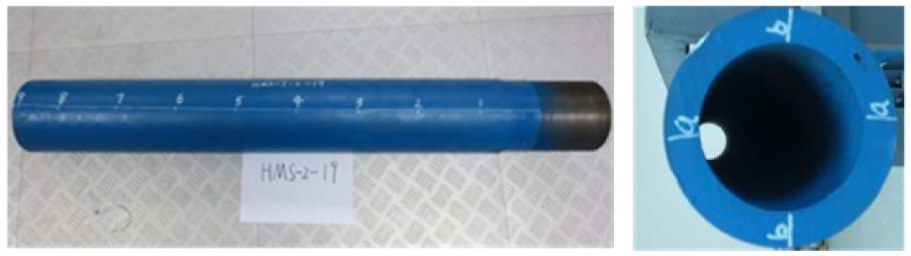
Labeling measurement diagram of CRLD anchor cables.
2. Installation of the strain gauge on the outer wall of the sleeve
Strain gauges are installed in the measuring point 2, the place between the measuring points 3, 4, and 5 and between the measuring points 6 and 7 and 8 on the outer wall of the constant resistance sleeve to mainly test the axial strain of the outer wall of the sleeve in the extension process. Before installation, the outer wall of the constant resistance sleeve was polished and the correct connection of the data cable was insured, as shown in Figure 6.
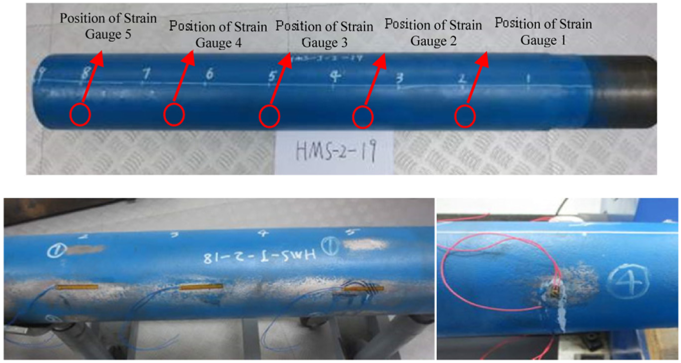
Strain gauge installation.
3. Installation of the infrared thermometer
The infrared thermometer of the constant resistance sleeve calculates the temperature based on the infrared radiation energy of the surface of the object. It is placed in the CRLD anchor cable static tension test system to realize the real-time measurement of the temperature of each point of the constant resistance sleeve, as shown in Figure 7.
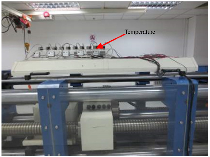
Temperature measurement test system.
4. Installation of the infrared thermal imager
The infrared thermal imager is installed on the tension system of CRLD anchor cables, as shown in Figure 8, to realize the real-time monitoring of the overall changes in the heat and temperature of the constant resistance sleeve in the extension process.

Installation of the infrared thermal imager.
Test process
The tension test of three groups of CRLD anchor cables was carried out by the constant rate control method at a rate of 20 mm/min, as shown in Figure 9. In the process of extension, the force, displacement, and load–displacement curve were obtained in real time; at the same time, the strain measurement system, infrared thermometer, and infrared thermal imager were used to obtain the axial strain of the corresponding measuring point of the anchor cable sleeve, the temperature–time variation trend, and the overall infrared thermal image of the sleeve, respectively, and the length of the constant resistance anchor cable and the outer diameter of the sleeve after extension were also measured.

CRLD anchor cable tension test.
Realization of the finite element model
Entity model establishment
ANSYS software was used to establish the finite element 3D entity analysis model consistent with the real structure. To improve the analysis efficiency, the one-fourth symmetrical model of anchor cables was established based on the geometric parameters listed in Table 1 and shown in Figure 10.

CRLD anchor cable 3D entity model.
Considering that the structural analysis and thermal analysis of the constant resistance body and constant resistance sleeve are involved in the extension process, the SOLID226 unit with both the functions of structural analysis and thermal analysis is selected; the steel strand mainly involves the structural analysis; therefore, the LINK180 unit with the function of structural analysis is selected. The grid model is divided into 4810 units and 7258 nodes.
Nonlinear analysis and settings of the anchor cable structure
The extension process of CRLD anchor cables belongs to the nonlinear large structural deformation contact problem, including material, contact, and state nonlinearity. The nonlinear deformation significantly affects the structure; therefore, it is necessary to analyze the extension process of CRLD anchor cables according to the nonlinear analysis theory, and the corresponding parameters are set up according to the physical and mechanical properties of the anchor cable materials.26–28
Nonlinearity of anchor cable materials
The CRLD anchor cable is an elastic–plastic nonlinear stress–strain material. The ANSYS program has provided a variety of options of plastic materials. Since the anchor cable has a large strain, multi-linear isotropic hardening model is used. This model is suitable for simulating large strain, and data that should be input are listed in Table 2. In the extension process of anchor cables, to minimize the deformation generated by the constant resistance body, the constant resistance sleeve is deformed to further generate constant resistance, so that the strength of the constant resistance body is much greater than that of the constant resistance sleeve.
Multi-linear hardening model parameters.

Nonlinearity of anchor cable contact
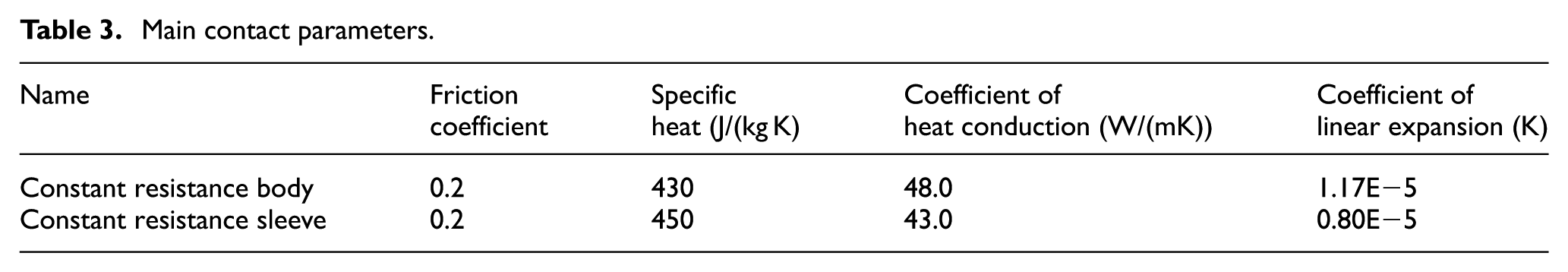
In the extension process of anchor cables, there is friction between the surface of the constant resistance body and the constant resistance sleeve. The frictional contact model is nonlinear. By designating the contact elements on the contact surfaces of the constant resistance body and the constant resistance sleeve, contact pairs are created to achieve surface-to-surface contact. In the process of establishing the contact, the friction coefficient and thermal contact parameters should be considered to realize the sliding friction thermomechanical effect. The main parameter settings are listed in Table 3.
Main contact parameters.
Nonlinearity of anchor cable state
In the extension process of anchor cables, the contact state of the constant resistance body and the constant resistance sleeve constantly changes. The axial restraint was set on the end face of the anchor cable sleeve at a constant rate of 20 mm/min on the extension end of the steel strand.
Finite element simulation process
After the above setting, the tensile force was applied to the nonlinear thermomechanical coupled solid model of the CRLD anchor cable at a constant moving rate of 20 mm/min, and the change in the equivalent stress of CRLD anchor cable with time is shown in Figure 9. With the sliding of the constant resistance body in the constant resistance sleeve, the overall length of the CRLD anchor cable continuously increases, and the outer diameter of the sleeve continuously increases. Time A to time F fully demonstrates the equivalent stress (SEQV) of the anchor cable during the extension process (Figure 11).

The dynamic plot of the equivalent stress (SEQV) of the CRLD anchor cable with time.
Indoor static tension test and numerical simulation results and analysis
Stress analysis of constant resistance anchor cables
The CRLD anchor cable is extended at a constant moving rate of 20 mm/min, and the load–displacement curve of the CRLD anchor cable shows three distinct stages: the linear growth stage (0–110 mm), this phase mainly relies on the elastic extension of the steel strand and the extrusion deformation between the constant resistance body and the constant resistance sleeve under the external load; the constant resistance stage (110–750 mm), when the external load exceeds the constant resistance value, the constant resistance body begins to slip in the constant resistance sleeve, because of the distinct mechanical properties of CRLD anchor cable, the curve of tensile force tends to be horizontal; in the detachment stage (750–900 mm), when the slip displacement of the constant resistance body reaches the designed length, the constant resistance body begins to gradually pass through the constant resistance sleeve, and thus, the tensile force is gradually reduced until it reaches zero. The selected load–displacement curve of the corresponding element of the model and the actual load–displacement comparison curve of anchor cables under stress are shown in Figure 12, and the test and simulation results were compared.
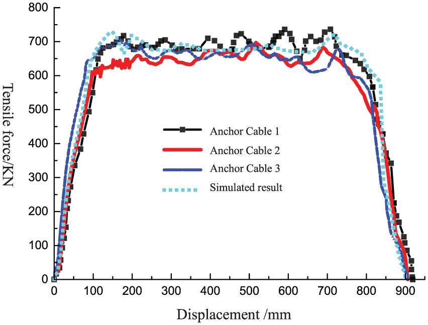
Load–displacement curve.
The test data of three groups of selected anchor cable are shown in Table 4. The indoor test results show that the average elongation and the average elongation rate of the three groups of CRLD anchor cables are 905 mm and 45.2%, respectively, and the constant resistance reaches 650 kN and fluctuates in the range from 620 to 700 kN under extension and thus is relatively stable.
Anchor cable test data.

Analysis of changes in the constant resistance anchor cable sleeve
Axial strain on the outer wall of the sleeve
At the end of the three groups of static tension tests, one group of test data was selected to draw the axial strain–time curve, and the experimental results were compared to the numerical simulation results, as shown in Figure 13 and Table 5.
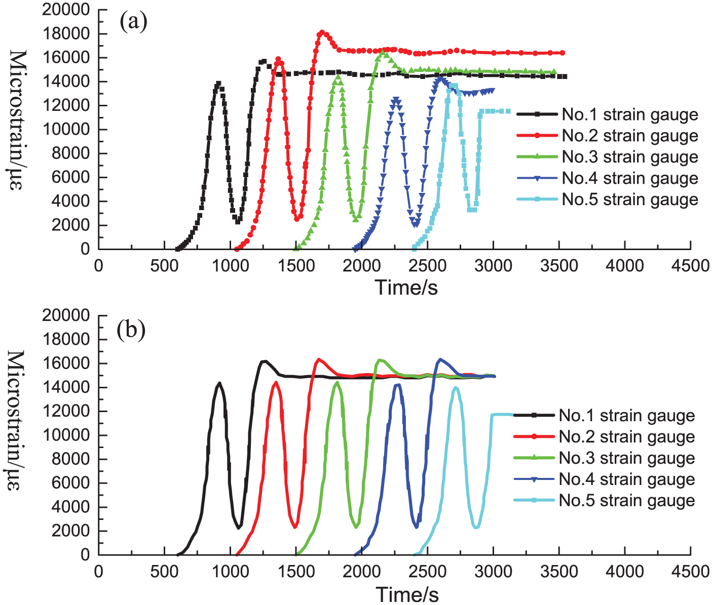
Axial strain–time curve of the measuring point of the outer side of the sleeve. (a) Test value of axial strain and (b) simulation value of axial strain.
Axial strain peak value of the measuring point of the outer side of the sleeve.

Figure 13(a) shows the changes in the axial strain at the corresponding measuring point on the outer side of the sleeve in the extension process of anchor cable test-piece as time elapses, and the curve in the figure reflects the course of the constant resistance body from contacting the measuring point to passing the measuring point. The axial microstrain of each measuring point gradually rises and then elastically falls, and then, it rises and falls again. Among them, the second fall is smaller than the first one, and finally, it stabilizes and remains at a certain level. The rise and fall of the part of the curve reflect the two courses of loading and unloading successively acting on the constant resistance sleeve; the condition that the stress is finally kept at a certain level indicates that when the constant resistance body passes through the constant resistance sleeve, that is, after the load is removed, an unrecoverable plastic deformation occurs. Therefore, the extension of the constant resistance anchor cable is not a simple elastic change but a spatial axis-symmetrical elastic–plastic contact process. 29 Because the changes in the subsequent measuring points affect the previous adjacent measuring points, the law of the axial strain curve from the measuring point 1 to 4 is relatively consistent, and after the constant resistance body passes the measuring point 5, it has passed through the end of the sleeve, and after the axial strain of the measuring point 5 is enhanced again, it tends to be stable.
Figure 13(b) shows the corresponding simulation results, which are relatively close to the test results, because the interference of the indoor test process is excluded. The simulation curve is more stable and smoother, and the final strain of each measuring point is basically the same.
Outer diameter variation of sleeve
A vernier caliper was used to cross-measure the outer diameter of the constant resistance sleeve in places from 1 to 9 of the three groups of CRLD anchor cables along the two vertical directions of a-a and b-b, and the average value of the outer diameter of each measuring point of the constant resistance sleeve was calculated, as shown in Figure 14 and along with the changes in the outer diameter of each measuring point of the numerical simulation sleeve.

Changes in the diameter of the sleeve.
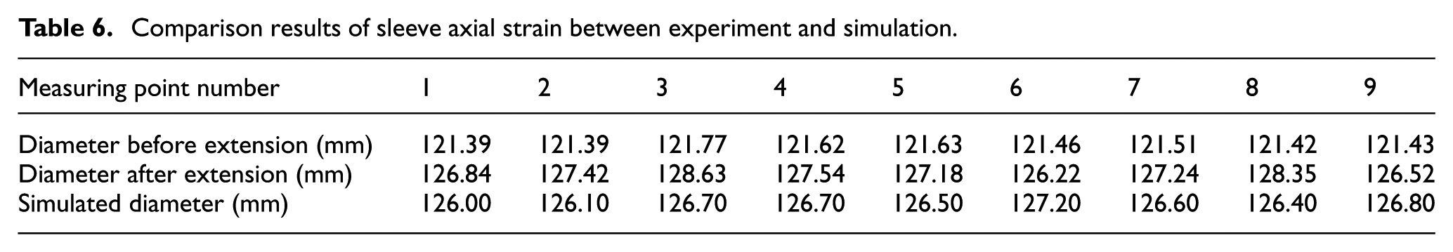
The comparison results of sleeve axial strain between experiment and simulation are shown in Table 6. The average outer diameter of the sleeve before extension is 121 mm, and the average outer diameter of the sleeve after extension is 127.3 mm, with an average increase of 6.3 mm. The numerical simulation results show that the average outer diameter of the sleeve after extension is 126.5 mm, and the changes in the outer diameter of the sleeve are basically consistent with the indoor test results. Both the test and simulation results show that the sleeve of the CRLD anchor cable expands and deforms in a radial manner. The reason for the deformation is that the constant resistance body with a larger outer diameter moves in the constant resistance sleeve with a smaller inner diameter, thus results in the expansion of the sleeve, and just because of this movement and expansion, the CRLD anchor cable shows CRLD.
Comparison results of sleeve axial strain between experiment and simulation.
Analysis of temperature changes at the measuring point of the sleeve
An infrared thermometer was used to monitor real-time trend of temperature changes at the measuring points of 1 to 9 of the constant resistance sleeve. The temperature–time curve is shown in Figure 15(a), indicating that when the constant resistance body slides to a certain point, the temperature will gradually increase up to 40° C, and after the sliding of the constant resistance body, the temperature decreases slowly. The temperature–time curve of measuring point 9 shifts due to the shaking of temperature sensor at the measuring point when the constant resistance body passes through the end of the sleeve. The increase in temperature for constant resistance anchor cables indicates that the energy absorbed by constant resistance anchor cables has been converted and transferred. In addition to converting into the deformation energy of the constant resistance device, a part of the energy is converted into the internal energy in the process of extrusion and friction between the constant resistance body and the sleeve and released in the form of thermal energy. Finally, the temperature of the sleeve reaches room temperature.

Comparison diagram between the sleeve temperature change test and numerical simulation: (a) test value and (b) simulation value.
The corresponding sleeve temperature–time simulation result curve is shown in Figure 15(b). Numerical simulation avoids the problem of sensor vibration that may occur in the test; therefore, the temperature–time curve (Figure 15(b)) more accurately reflects the variation law in the temperature at each measuring point of the CRLD anchor cable in the process of static tension. Both the test and the simulation results show a gradual increase in the peak value of the temperature curve, because the temperature of the constant resistance body continues to rise in the sliding process, so that the starting temperature of the follow-up measuring points is higher than that of the previous measuring points of the sleeve when it contacts the constant resistance body. The comparison results of temperature peak value between experiment and simulation are shown in Table 7.
Temperature peak value of the measuring point of the sleeve.

The real-time monitoring of the temperature and energy of the constant resistance sleeve in the process of static tension was monitored using an infrared thermal imager, and the results are shown in Figure 16, indicating that when the constant resistance body is moving in the sleeve, the temperature in the constant resistance sleeve will rise sharply. As the constant resistance body continues to move, internal energy generated by the friction between the constant resistance body and the sleeve will be released in the form of thermal energy, and finally, the temperature of the sleeve reaches room temperature. According to the temperature difference interface in the thermal infrared image, the sliding position of the constant resistance body in the sleeve can be determined.

Thermal infrared effect diagram of the sleeve.
Conclusion
In the static tension test of CRLD anchor cables, the mechanical properties of anchor cables were determined, and the finite element software ANSYS was used to analyze the results. The experimental results and simulation results were compared. The conclusions of this study are as follows:
The static tension test measurement results show that this batch of CRLD anchor cables can maintain a constant resistance of 650 kN under the static tension conditions, and simultaneously, the tensile deformation rate reaches up to 45.2%, indicating that CRLD anchor cables are characterized by good CRLD. The CRLD anchor cable has overcome the drawbacks of invalid yield of traditional anchor cable material or breakage of the anchor head and thus meets the requirements of deep soft rock roadway support and monitoring of landslide in advance.
The CRLD anchor cable can absorb the deformation energy stored in the rock mass through structural deformation, and the anchor cable can still maintain a constant resistance and generate large deformation during the process of energy absorption, so that the rock mass develops toward a new balanced support. In the process of static tension of CRLD anchor cables, the temperature of constant resistance anchor cables rises, indicating that in addition to the deformation energy of the constant resistance device, part of the energy is converted into the internal energy in the process of extrusion and friction between the constant resistance body and the sleeve and released in the form of thermal energy.
According to the theoretical model of CRLD anchor cables, the structural nonlinear thermomechanical coupling numerical model was established. The numerical analysis vividly reproduced the extension process of anchor cables and simultaneously avoided the disadvantage that the indoor test is susceptible to external interference and accelerated the extraordinary mechanical property test and evaluation speed of constant resistance anchor cables. The numerical simulation results show that the elongation of this type of anchor cables is 902 mm with an elongation rate of 45.1% and a constant resistance of 660 kN, which are basically consistent with the experimental results, indicating that numerical simulation is relatively accurate for testing the mechanical property of CRLD anchor cables, and the combination of the indoor test and numerical simulation provides the reference for engineering practice and design optimization of CRLD anchor cables.
Footnotes
Acknowledgements
Gang Zhi Tao and Wenshuai Han contributed equally to this work.
Handling Editor: William Guo
Declaration of conflicting interests
The author(s) declared no potential conflicts of interest with respect to the research, authorship, and/or publication of this article.
Funding
The author(s) disclosed receipt of the following financial support for the research, authorship, and/or publication of this article: This study is supported by the National Natural Science Foundation of China (No. 41502323) and Beijing Natural Science Foundation of China (8142032).