
Abstract
This article considers a robust decoupling controller design for a multivariate control system with parameter uncertainties for the hot rolling mill process. The left and right coprime factorization theory is used to properly select the free and weighting matrices. The necessary and sufficient conditions for robust decoupling controller are also proposed. Then, by analyzing the changes in the dynamic response resulting from perturbations in the tension and angle system parameters in the hot strip rolling process, a modified multivariate model is developed. Furthermore, the selection method for a practical weighting function is studied, so that the robust and decoupling performance can be simultaneously realized for the controller implementation. Finally, the effectiveness of the proposed control approach is demonstrated using a case study from an industrial hot rolling mill.
Keywords
Introduction
The hot strip mill process (HSMP) is a high-speed, transient metal machining molding process.1–3 In the steelmaking process, stable product quality and safe, reliable operation of a hot strip rolling mill are the main control objectives. The dimensional quality specification, 4 consisting of thickness, width, flatness, and profile of the strip, can be controlled and operated by a dedicated control system, such as the automatic gauge control (AGC), the automatic width control (AWC), the automatic shape control (ASC), and the automatic position control (APC) systems. For the stable operation of a rolling mill, with smooth strip threading and steady mass flow during the strip rolling process between rolling stand, the mass flow control system is required to regulate the stored loop length and change the speed of the drive mill motor. Of the control systems that can directly or indirectly influence the specifications of the HSMP, the looper control system, whose controlled outputs are the strip tension and looper angle, is a key subsystem for the safe rolling process and stable strip quality. Strip tension control is extremely important since it can affect both the dimensional quality and the mass flow of the strip.5,6 Sometimes, there is a need to consider a trade-off between the two specifications, that is, the strip tension should be kept at a desired value during rolling operation to ensure stable strip quality and threading. The looper angle, however, can be changed by moving the looper up and down, in order to absorb any excessive strip looping due to a mass flow imbalance. In ideal circumstances, the looper angle should also be maintained to a desired value during operation to reduce tension variations and maintain the flexibility in achieving the desired results given unexpected changes in loop length under complex working conditions.
The most difficult issues in the looper control system7–9 are realizing simultaneous control of strip tension and looper angle, since these two interact with each other, leading to a typical multivariate coupled system. Previously, due to limitations in the skills of the operators and the simple nature of the control system implementation, single-input, single-output (SISO) control methods were widely used in many looper control systems, where the angle and the tension are controlled separately. However, there is significant interaction between strip tension and looper angle, which degrades the control performance and stability, which the SISO control system cannot handle. This inability to control leads to performance degradation with outcomes such as slow dynamic response, low control accuracy, and difficulties in parameter reconfiguration. The demand for strip quality in the HSMP has required further advances in the control system design and implementation. Seki et al. 10 proposed a multivariate coupled model that has since drawn much attention in both academia and industry. Although this model can be recognized as the foundation of multivariate decoupling control design in the looper control system, the parameter perturbation and variation issues caused by faults, disturbance, and roll specification under complex working conditions, which are especially common in the modern strip rolling process, are not discussed. In particular, increasing use of low-temperature heating of slabs, high-carbon steel, and higher rolling speed will all require additional unique models to be developed. Furthermore, the aforementioned model is relatively suitable for describing the up-and-down action of the looper, while the system performance and strip quality can be improved better during continuous steady strip rolling, which requires a modified model for the steady rolling processes.
H∞ control, as one type of robust control theory, has drawn much attention, since its first emergence in the 1980s, and has became a critical research field in control engineering,11,12 which is mainly used to design and tune the controller based on different working conditions of the plant, even under worst case. Most of the important results focus on the parameter design of the robust controller, both for SISO and multiple-input, multiple-output (MIMO) systems. However, there are not many approaches to realizing the integrated design of robust control and decoupling control simultaneously, and few of them derive the realization algorithm for parameter reconfiguration and tuning. Xu et al. 13 proposed a decoupling design method using H∞ optimal design theory to obtain controllers that have both optimal sensitivity and robustness for MIMO systems. In Zeng et al., 14 by considering the coprime factor uncertainties both in the plant and controller, robust stability and nonfragile decoupling control of a closed-loop system is derived. As well, the sufficient conditions for the problem and optimization design algorithm are provided. Compared to the two references which primarily focused on the theoretical part, Jing et al. 15 proposed a feed-forward decoupling–based robust control method to guarantee the decoupling performance under parameter uncertainties and verified its effectiveness on the gauge-shape control system benchmark in the strip rolling process. This result is a good initial application of robust controller in industrial fields. However, it cannot realize the simultaneous robust decoupled control due to its design procedure, which leads to separate design for a robust controller and a decoupled controller. Thus, it cannot guarantee optimal operation during the complex working conditions for strip rolling processes.
Motivated by the aforementioned studies, this article proposes a robust decoupling mixed sensitivity controller for the looper control system. It can be noted that in order to improve the performance of the proposed controller, an improved process model is also developed, where the influence of parameter perturbation in the strip tension and looper angle is considered. Based on coprime factorization theory, the free and weighting matrices for the H∞ framework are selected, and the necessary and sufficient conditions for robust, decoupling controller are proved. Then, the robust, multivariate decoupling controller is simultaneously designed by selecting proper practical weighting functions based on control performance requirement. Finally, the performance and effectiveness are demonstrated through an experimental case study from the last rolling stand of a 1580-mm hot rolling mill.
The design and realization of the robust decoupling controller
Background
Consider the controlled system shown in Figure 1, where Figure 2 is the expanded structure of Figure 1. In Figures 1 and 2, U is the reference signal; E is the error; Y1a, Y1b, and Y1c are the outputs from the three weighting functions W1, W2, and W3, respectively; C is the controller; P is the plant; and δ is the Dirac delta function. In the mixed sensitivity–based robust controller design problem, which is a typical problem in H∞ control, the three weighting functions W1(s), W2(s), and W3(s) need to be designed based on the expected control performance indicators. As shown in Figure 1, let

where S is the sensitivity function that shows the magnitude of the tracking error and T is the complementary sensitivity function that reflects the influence of uncertainty and disturbances on the system. The mixed sensitivity method is to realize the integrated design of functions S and T. If we focus more on the performance improvement of the system tracking behavior, that is, better system dynamic response, the weighting function W1(s) should be chosen properly. If we focus more on the robustness performance, the weighting functions W2(s) and W3(s) are the design targets, which make the system output signal remain stable against uncertain parameter perturbation. In fact, we should seek a trade-off between S and T based on the different performance requirements of the actual industrial system.

The mixed sensitivity–based robust control system.

The augmented system diagram with two terminals.
Figure 2 shows the augmented system diagram with two terminals, which is the transformed form of Figure 1, which we can obtain by considering reference tracking and disturbance attenuation, where Y is the process output. Since the transfer function from u1 to y1,

Designing the controller
The next step in the design of the robust decoupling controller is to determine its realizability, that is, if given certain conditions, a controller can actually be designed and implemented. In order to solve the problem of the design and realizability of the robust decoupling controller, the following three subproblems need to be considered:
The solvability of the controller parameter, C ∈ S(P), where S(P) is the set of all stabilizing controllers;
The robustness of the system, such that
The diagonalizable matrix design of sensitivity function S and complementary sensitivity function (I − S), to realize simultaneously decoupling for multivariate closed-loop system against disturbance and tracking error.
Since a discussion of the stability and robustness subproblems can easily be found in the literature,11,12,14 this article will focus on how to compute the controller parameters and obtain a diagnosable matrix for S and (I − S), which means that the closed-loop system is decoupled.
Theorem 1
Realizability of the controller
For a given square system P(s),
Proof
If direction
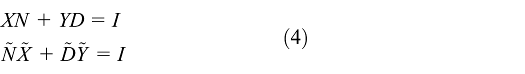
For a given nominal system P(s), its right coprime factorization (r.c.f.) and left coprime factorization (l.c.f.) are

Likewise, the r.c.f. and l.c.f. of the controller are

Based on Bézout’s identity
For simplicity, let

From equation (5), we have that

Then, based on the double Bézout’s identity, the follow relationship can be obtained

Since
Only-If direction
For a system of linear equations, if

where Q is the parameterization matrix. This matrix can be given based on the control purpose, subject only to Q(s) ∈ H∞. When Q equals to zero, we can get the particular solution for a robust controller.
Substituting equation (8) into equation (4) allows the rationality of solutions to be determined, that is

From equation (2), substitute

According to equations (10) and (5), once the free matrix Q is selected, the controller can be solved, and the solutions of controller parameter of the nominal system exist and satisfy

where C is the stabilized feedback controller of system P(s).
Remark
A system that has the same amount of inputs and outputs can be defined as a square system. In industrial processes, many multivariate systems can be defined or transformed into square systems.
Theorem 2
Diagonalization
For a given nominal square system P(s) with predetermined parameters, let the r.c.f. and l.c.f. be defined as (N, D) and (
Proof
According to equations (9) and (10), we know that

From equation (10), we have that

while equation (5) gives

Substituting equation (13) into equation (12), we get

Then, the Q-matrix can be expressed as

The proper solution for equation (15) is

Finally, substituting this solution into equation (11) gives

Since for any nonsingular matrix, the product of the matrix with its adjoint is a diagonal unimodular matrix, we can show that the transfer function matrix of the closed-loop system and its sensitivity function S are both diagonal matrices. Thus, we can show that the system can be decoupled both for tracking and perturbation/disturbance attenuation by the mixed sensitivity–based robust control.
Industrial implementation of the proposed robust decoupling controller
In this section, the proposed robust decoupling controller will be tested on the looper–tension control system. Figure 3 shows a looper installed between rolling stands that can be used to reduce tension variations by changing its angle. As well, a looper allows for stable operation of the process by absorbing excessive loop resulting from a mass flow imbalance. The looper control system, which is also called the looper and tension control system, shows that the strip tension and looper angle are the two key factors to be controlled. In the HSMP, the looper begins to work by moving up to contact the strip and, at the same time, changing the strip tension and looper angle. In fact, the looper angle will increase as the tension decreases and increase as the tension decreases. The looper is usually driven by a hydraulic system, as shown in Figure 4, where AHR is the automatic hydraulic regulator. Traditionally, conventional proportional–integral (PI) control has been used on the looper control system in industrial fields. However, due to the significant interaction between strip tension and looper angle, using PI control, control performance and the stability cannot be maintained during complex rolling conditions.

Lopper system between rolling stands.

Looper angle and tension control in finishing mills.
Improved model of the looper–tension control system
The two-input and two-output multivariate system of looper angle and tension system has been developed to give a more accurate model and better control performance.
10
Using this approach, an improved coupling model that relaxes some of the assumptions and allows for the consideration of model uncertainties during dynamic rolling processes is proposed in this article. The proposed new looper–tension system structure is shown in Figure 5, where

The coupled model diagram of the looper–tension system.
A detailed description of the changes compared with the original method described in Seki et al. 10 are as follows:
The sign of KV is changed from positive to negative, since ΔV is now regulated by the upstream rolling stand, where an increase in the rolling speed will lead to a decrease in the strip tension.
The sign of the coupling effect due to the looper angle from the tension, KMσ, is defined as negative. The sign of the coupling effect due to the tension from the looper angle, KVθ, is defined as positive. This shows that without control, the looper angle will decrease as the strip tension is increased, while the tension will increase as the looper angle increases.
In order to focus on the dynamic control process after the looper moves up, as well as to make the model more suitable for hydraulic looper driven system in modern strip rolling mills, a new parameter Kθ is defined.
Due to different strip specifications, set points, rolling speeds, and external disturbances, parameter uncertainties exist under complex working conditions, which leads to parameter perturbations, for instance, KVσ depends on the rolling speed and tension, while Kθ depends on the speed of strip rolling and looper moving.
With the above improvements, the first principles, state-space model for the system is
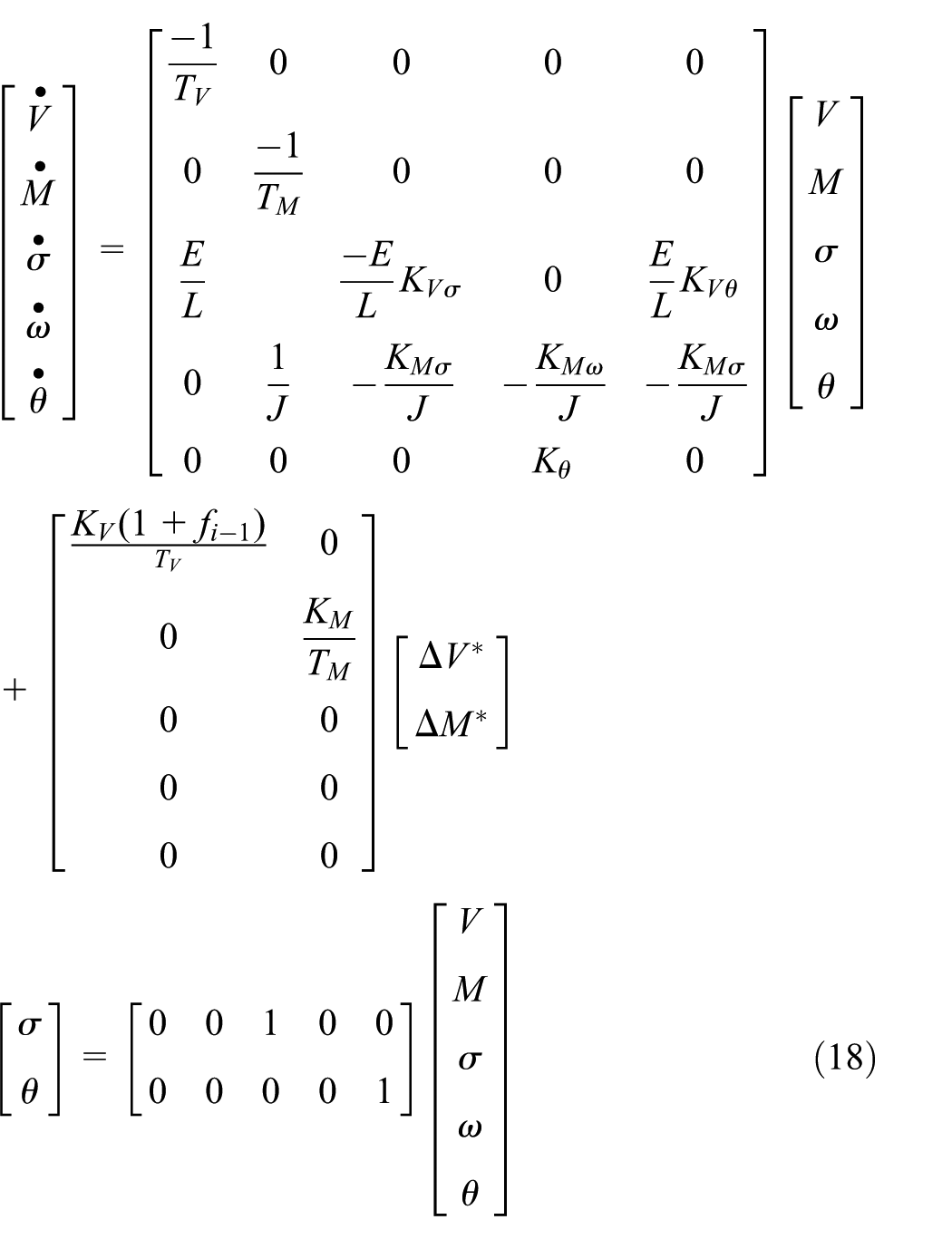
where the parameters are given as follows, using actual process information from an industrial hot strip mill stand: KV = 1, TV = 0.0885 s, KM = 0.5, Kθ = 6.28, TM = 0.0324 s, J = 0.48 kN m2, E = 210 kN/mm2, L = 4.5 m, KVσ = 0.3586, KMw = 0.3586, KMθ = 0.3428, KMσ = 0.0255, KVθ = 0.2631, and fi − 1 = 0.06, and the coefficient matrices in state equation (18) are

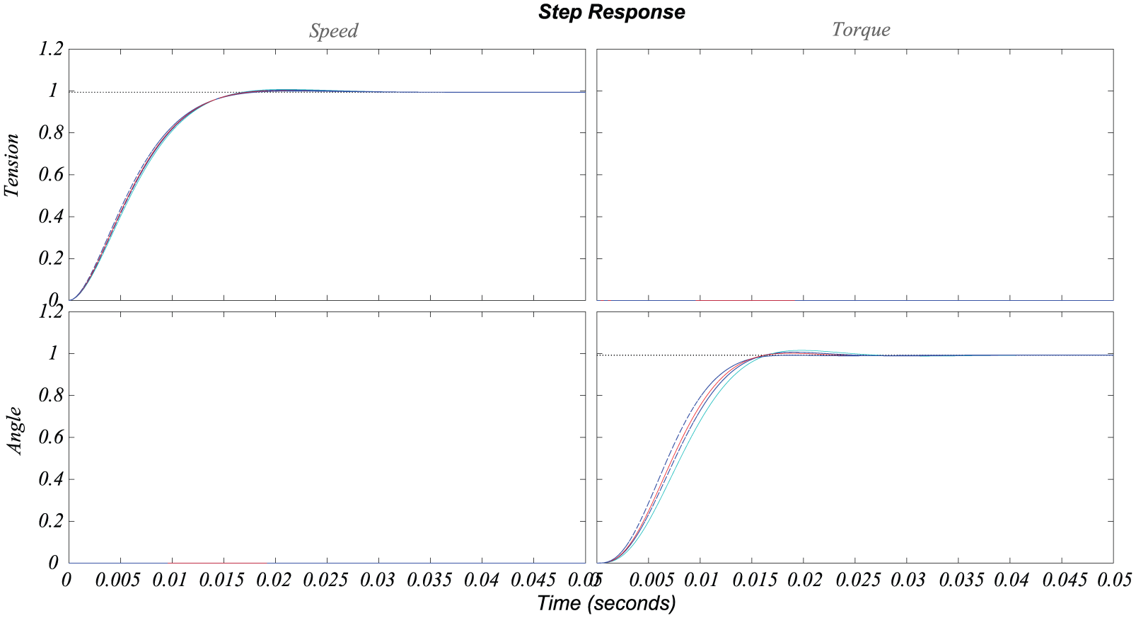
During the dynamic rolling processes, there are many factors causing parameter perturbation, such as external disturbances, faults, and aging of the mechanical equipment, which will usually lead to the variation of steady rolling speed. For instance, if the steady-state rolling speed is 10 m/s and rolling speed is changed by ±1.5 m/s due to the aforementioned parameter perturbation. 16 Figure 6 shows the response of the system with conventional PI controller to a step excitation with the consideration of parameter perturbation. The red curve in the figure is the system response in nominal steady rolling state (10 m/s), and the blue curves are its response under different parameter perturbations. It should be pointed out that the parameter perturbations induce performance degradation of the looper angle–tension control system. Moreover, as can be seen from the images in the upper right and lower left, there are strong coupling effects between the looper angle and strip tension control systems. Thus, a robust decoupling mixed sensitivity controller is necessary for better dynamic/steady performance of the looper control system.

The step response of the coupling uncertainty model.
Designing the robust decoupling controller
The selection of weighting functions is extremely important for the implementation of the proposed robust decoupling controller, since it is not only related to control performance on the decoupling effects of external disturbances, but also affects the dynamic response characteristics of the system. Based on the results of the existing literature17–19 and the authors’ engineering experience in the industrial field, the frequency bandwidth of the weighting function should be equal to the desired frequency bandwidth of the system. Based on that, the selection of weighting function can be defined as

where W3(s) is the reciprocal of W1(s) and A < 1 is the maximal steady-state error, that is, if A = 0.005, the steady-state error is 0.5%, that is

where M > 1 is the peak value of the sensitivity, which can affect the step response of system at t = 0+. It should be larger if a larger step response is expected, for example, if M = 100, this implies that the step response is 1%, that is

where ω0 is the desired bandwidth, which can affect the desired system response speed after decoupling, for instance, if the system adjustment time is Ti ⩽ 25 ms, ω0 = 200, since ω0 = 0.707ωc, where ωc is the system cut-off frequency, that is

Then, based on the proposed looper–tension model and system performance requirement of hot strip rolling process, the weighting functions can be derived and calculated using the Riccati algorithm method and the MATLAB Robust Toolbox 20 to give

Figure 7 shows the control performance using the proposed robust decoupling control algorithm, which is designed based on the nominal state of the system model. It should be noted that the same system model parameters are used as in Figure 6, and the simulation scenario such as the parameter perturbations is also the same. The red curve shows the response of the nominal steady rolling state, and the blue ones are the response for different parameter perturbations. It shows that even under changeable rolling speed resulting from parameter uncertainties, the looper angle–tension system remains robust. Comparing the upper right and lower left images of Figures 6 and 7, it can be seen that the system output is fully decoupled when using the proposed robust decoupling control algorithm. Meanwhile, the setting time for the strip tension and looper angle system is less than 25 ms for both systems, and the dynamic response can track the reference signal in a very short time.
The step response of the system with robust decoupling controller.
Implementation in an industrial process
In this section, to verify the effectiveness and performance of the proposed robust decoupling controller algorithm, an implementation on a looper–tension system of the last stand finishing mill in a 1580-mm hot strip rolling process is performed. Due to the higher rolling speed of the last stand finishing mill, leading to larger parameter perturbations and stronger system coupling, it can be treated as a suitable case study for the proposed control algorithm. The model structure is consistent with the proposed looper–tension model, and the parameters come from industrial rolling mills. Table 1 gives the operating parameters for the case study. As a matter of fact, there are several strip specifications and rolling schedules for this HSMP, the reason to choose this set of parameters is that it is relatively close to the nominal state of the aforementioned model. However, some other cases will also be discussed to give a more comprehensive control performance evaluation.
The parameters of the rolling process.

The strip tension and looper angle are obtained from the angle encoder of the looper system and tension sensor in the hydraulic strip tension system. After calculating the controller parameters using the MATLAB Robust Control Toolbox, the robust decoupling controller C(s) must be converted into the programmable logic controller (PLC) control units. It is worth noting that, during the data sampling of the looper–tension system, there is a variation in the tension set point (up to 4 MPa) and looper angle set point (up to 28°), which is common in the dynamic rolling process. The response data are collected by a 2-MHz high-frequency oscilloscope and transmitted to MATLAB. 20 Figure 8 shows the response curve.
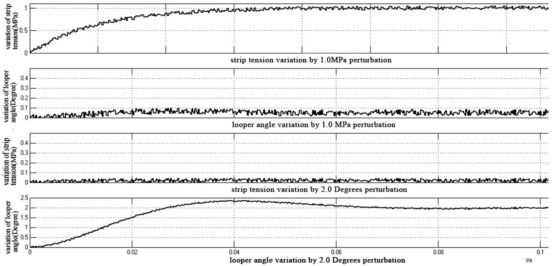
The step response of the system with parameter perturbation.
In Figure 8, when there is a 1.0-MPa perturbation in the strip tension set point (from 3.0 to 4.0 MPa), it can be seen that in the top two images, the strip tension output will achieve the desired set point in no more than 50 ms, and there is only a 0.05° coupling output for looper angle system. Similarly, when there is a 2.0° perturbation in the looper angle set point (from 26° to 28°), we can see in the bottom two images that the looper angle output will achieve the desired set point in less than 60 ms. As well, there is almost zero effect for strip tension system arising from the looper angle perturbation, which can be directly shown in the middle two images. This case study shows that the industrial system can maintain its robustness and realize parameter decoupling using the proposed control algorithm, even under parameter perturbations.
To give a better comparison between the proposed robust decoupling control approach and the current controllers, which are usually implemented by two PI controllers, one each for the angle and tension control loops. The control performance comparison is shown in Table 2. The advantage of the proposed approach on the decoupling effect is straightforward, while the settling time under different cases of system perturbation, the performance of the proposed method seems to be more or less the same or even a little bit worse than the current PI control approach. The main reason about this issue is inevitable, due to the characteristics of robust control theory, which only design one controller that considers all circumstances. The nominal rolling speed in the aforementioned model is 10 m/s, and the PI controllers in the 1580-mm HSMP is tuned mainly based on its 10.5-m/s rolling schedule. This explains why it seems that the settling time is better for the current controllers than for the proposed controller. Moreover, another comparison is also made to show the robustness advantage using the proposed approach, which can be seen in Table 3. It is worth noting that with the higher speed of rolling and thinner strip thickness, even under the same case of perturbation, the robust decoupling control approach not only has a smaller coupling effect, but also a shorter settling time, since when away from the nominal system state, the robust controller contributes more to the robustness due to system uncertainties under different working conditions.
The control performance comparison with 3.5-mm thickness and 10.5-m/s rolling speed.

The control performance comparison with 2.85-mm thickness and 13-m/s rolling speed.

Conclusion
To deal with parameter perturbation and coupling effect in multivariate looper angle–tension system of HSMP, this article proposed a robust decoupling control algorithm based on mixed sensitivity functions. The theory regarding the simultaneous realization of robustness and decoupling in multivariate systems has been presented using the mixed sensitivity method. The improved model of the looper system is developed and the characteristics of the parameter coupling effect are analyzed. Through the case study, both a simulation model and an industrial application are used to show the performance and effectiveness of the proposed control algorithm to deal with parameter perturbation and coupling effect. Although the benchmark study and industrial application provide satisfactory results, the design of simultaneous robust, decoupled control for fault-tolerant purposes should be considered in the future.
Footnotes
Handling Editor: Xihui Liang
Declaration of conflicting interests
The author(s) declared no potential conflicts of interest with respect to the research, authorship, and/or publication of this article.
Funding
The author(s) disclosed receipt of the following financial support for the research, authorship, and/or publication of this article: This work was supported by the National Natural Science Foundation of China under grant no. 61673053, the Beijing Natural Science Foundation under grant no. 4162041, and the National Key R&D Program of China under grant no. 2017YFB0306403.