
Abstract
Due to the sweep excitation of the vibrator, the dynamic stiffness of the seismic vibrator has an enormous influence on the performance of the vibroseis system and the accuracy of the output signal. In order to improve the dynamic stiffness of the vibrator, an optimization strategy is presented to improve the weak link which is defined by dynamic analysis of the vibrator. The weak link is the weakest part, which brings about the resonance, and the weak link in different excitation frequencies is identified by dynamic stiffness analysis in this method. A modified finite element model with reaction mass is built; harmonic response analysis and modal analysis are employed to find out the weak link of the vibrator, which indicates that the supporting column is the weakest component. Sensitivity analysis is used to determine the optimization parameters of the supporting column. Response surface model developed from a parametric finite element model is used to establish the objective function, and the mass is the constraint condition. The optimization problem is solved by particle swarm optimization, and the dynamic stiffness of the optimized vibrator is calculated by harmonic response model. Results show that compared with the original model, the natural frequency of the optimized vibrator is increased by 6.63% and the resonance peak is decreased by 9.00%.
Keywords
Introduction
Seismic vibrator is widely used in gas and oil exploration due to high efficiency and environmental protection. Due to the increase in the exploration demand, high precision and wide bandwidth are the main development trends of the seismic vibrator. As the key component of the vibroseis, performance of the vibrator determines the frequency and accuracy of the output signal. Hence, the study of performance of the vibrator has always been an area of research interest. Researches have proved that the stiffness of the vibrator baseplate is one of the main reasons which limit the performance of the vibrator.1–5 For example, Baeten and Ziolkowski 6 proposed a model to account the flexion of the baseplate, and the model showed that the baseplate stiffness is mainly of importance at high frequency. Due to the sweep excitation ranging from 5 to 125 Hz, response of the vibrator varies at different frequencies. Thus, the dynamic stiffness of the vibrator has great effects on the performance and output signal of the vibrator. Wei 7 established a finite element model of vibrator and coupling ground to simulate dynamic response of vibrator and analyze different vibration modes of the vibrator. Hall 8 and Huang et al. 9 investigated that the improvements of vibroseis output signal quality at both low and high frequencies can be achieved by increasing the stiffness of vibrator baseplate.
In conclusion, increasing the stiffness of the vibrator is a good way to improve the performance of the vibrator. Consequently, many optimization methods have been proposed to improve the vibrator stiffness. The Failing Company 10 applied a new archy vibrator baseplate. Wei and Phillips 11 developed a new vibrator baseplate which composed at least partially of a composite material, and it is found that the composite baseplate is beneficial to reduce vibrator’s mass and to increase structural rigidity. Ma et al. 12 studied the static stiffness of seismic vibrator using mechanical vibration theory. A finite element model was established to analyze the effect of vibrator structure and flitch plate on the vibrator deformation. The research indicated that the vibrator deformation can be reduced through optimization of vibrator structure and flitch plate. However, most of the optimization researches of the vibrator stiffness are limited to optimize in the static design phase and ignore the dynamic characteristics of seismic vibrator. The vibrator is excited by sweep signal; the characteristics and stiffness of the vibrator are different at different frequencies. Thus, a dynamic optimization design is essential to find out the weak link and determine the optimization objective of the vibrator.
To increase the efficiency of the optimization, in this article, an optimization strategy is proposed, and the dynamic characteristics of the vibrator are taken into account. A modified finite element model with reaction mass is constructed, and harmonic response analysis and modal analysis are used to identify the weak link of the vibrator. Analysis results show that the supporting column is the weak link of the vibrator dynamic stiffness. Sensitivity analysis is employed to determine the optimization parameters of the supporting column. For the optimization, response surface model is used to construct the optimization function, and the optimization function is solved by particle swarm optimization (PSO) algorithm.
The framework of the dynamic stiffness optimization
To present the main structure of vibrator, a schematic sketch of seismic vibrator is illustrated in Figure 1. The vibrator is consisted of top plate, piston, supporting column, baseplate pad, and reaction mass. The top plate, the piston, the supporting column, and the baseplate pad are firmly connected together and called the vibrator baseplate. The vibrator system can be simplified as two-degree system which consists of the reaction mass and the vibrator baseplate, as shown in Figure 2.

The schematic sketch of vibrator.

Mechanical model of vibrator.
According to the mechanical vibration theory, the differential equation of motion of the vibrator system can be expressed as

where
Due to the simple structure of the reaction mass, the stiffness of the vibrator is usually improved by modifying the vibrator baseplate in engineering. In order to obtain the dynamic stiffness of the baseplate, the frequency response is written as
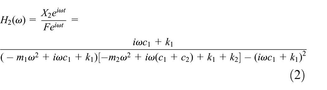
where
As can be observed from equation (2), the dynamic stiffness of the vibrator baseplate decreases with the increase in the response amplitude. The dynamic stiffness of the vibrator baseplate reaches the minimum value when the excitation frequency


where

Due to the damping ratio

From the above equations, it is inferred that the natural frequency of the vibrator increases with the increase in the stiffness coefficients. Thus, improving the stiffness is an efficient way to increase the natural frequency of the vibrator. The equivalent stiffness coefficient

where
A complete simulation model of the vibrator is built to analyze the dynamic stiffness of the vibrator. Through the harmonic response analysis, the resonance point with the biggest resonance peak can be found out which is the weakest point of the vibrator dynamic stiffness. Subsequently, modal analysis is used to analyze the mode shape of the biggest resonance peak. And, the weak part which brings about the resonance can be obtained through the modal strain energy analysis.
According to the structural dynamic analysis results, sensitivity analysis is employed to study the relationship between the design parameters and the objective natural frequency. And, the parameter which has few effects on the frequency will be ignored in the optimization. Response surface model is introduced to establish the objective function. Central composite designs method is used to design the numerical experiments.
The optimization problem can be defined including the objective function, the constraints and the design domain. PSO algorithm is employed to solve the optimization problem, and the optimal solution is verified by the finite element model built by ANSYS software.

The flowchart of the optimization.
Dynamic stiffness analysis of the vibrator
Model of the vibrator dynamic stiffness analysis
Geometry and meshing
It is very difficult to obtain the accurate dynamic stiffness of the vibrator under the operating conditions due to the complex structure of the vibrator. However, the finite element analysis provides an efficient approach to analyze the vibrator. Existing simulation model of the vibrator ignores the reaction mass, which applies hydraulic load to the piston directly. According to the above analysis, the mass of the reaction mass has an effect on the frequency response of the vibrator baseplate which cannot be omitted in dynamic stiffness analysis. In the hydraulic system, hydraulic oil is compressed in the same way as the springs. 15 The stiffness of the spring between the reaction mass and piston is 3.2e6 N/m. In order to ensure the relative movement between the reaction mass and piston, the reaction mass is connected with the piston by kinematic pair. Other bolt connections of vibrator are simplified as fixed connections. Chamfers and fillets of vibrator which may cause high mesh warpage are omitted. Figure 4 shows the complete geometric model which can reflect the main structure of the vibrator. Due to the complex structure of the vibrator, the vibrator is meshed with tetrahedron elements. The size of the elements is from 10 to 20 mm, and there are 250,379 three-dimensional (3D) elements for modeling the vibrator.

Complete geometric model of vibrator.
Materials properties and static load
The material of the vibrator baseplate pad is A210C steel, and the material of the other components is 1045 steel. The detailed material parameters of vibrator are shown in Table 1.
Material parameters of vibrator.

The vibroseis is lifted up and the weight of the vibroseis is loaded on the vibrator during the working process. In total, 90% of the vibroseis weight is loaded on the top plate and 10% of the weight is loaded on the baseplate pad, as shown in Figure 5.
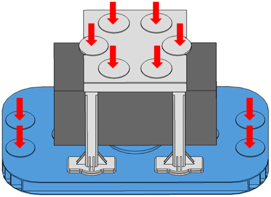
Location of vibroseis’ weight.
Identification of the weak link of the vibrator dynamic stiffness
Through the static analysis with ANSYS software, the stress caused by loaded weight of the vibroseis can be simulated. The result of static analysis is transformed into initial conditions during the pre-stressed harmonic response analysis. The acceleration load is applied to the reaction mass with frequency ranging from 1 to 500 Hz in the Z-direction. The relationship between amplitude and load frequency is shown in Figure 6.

Frequency response of seismic vibrator: (a) X-direction, (b) Y-direction, and (c) Z-direction.
The pre-stress load can cause the deformation of the vibrator baseplate. Due to the flexure of the piston, there will be interaction force between the reaction mass and the piston in three directions. Thus, resonance of the vibrator can occur in the X-, Y-, and Z-directions. It is shown that there are multiple resonance peaks of the vibrator in the X-, Y-, and Z-directions. The frequency of the biggest resonance peak in the X-direction is about 470 Hz, the frequency of the biggest resonance peak in the Y-direction is about 41 Hz, and the frequency of the biggest resonance peak in the Z-direction is about 490 Hz. According to the above analysis, these three resonance peaks correspond to the weakest dynamic stiffness point of the vibrator.
Using modal analysis, the main structure of vibrator which brings about resonance can be identified. Due to the exciting frequency of the vibrator ranging from 5 to 125 Hz, the biggest resonance peak in the X- and Z-directions can be not taken into account. The displacement mode shape of the vibrator at 40.982 Hz is shown in Figure 7(a). From the displacement mode shape, it is shown that the supporting column drives the vibrator to swing in the Y-direction. The swing vibration of the supporting column is the main reason which brings about the biggest resonance peak in the Y-direction. Thus, the supporting column is the weak link of the vibrator, and optimizing the structure of the support column is an efficient way to improve the dynamic stiffness of the vibrator. Although the displacement mode shape can make an intuitional description for the natural characteristic of the structure which is beneficial to find the weak link, it cannot display the maximum deformation of the baseplate. The modal strain energy of the vibrator can be expressed as 16

where

Modal analysis of the vibrator: (a) mode shape and (b) modal strain energy.
According to equation (8), it is inferred that the higher the model strain energy is, the larger the displacement is and the lower the stiffness of the structure is. The maximum modal strain energy can reflect the inefficient local stiffness of the supporting column, which is beneficial to the determination of the optimization parameters. Thus, it is necessary to extract the modal strain energy of the vibrator, as shown in Figure 7(b).
Design parameters of the supporting column
As can be seen in Figure 7(b), the maximum strain energy mainly appears on the reinforcing plate and the crossbeam. Thus, these two places are the weak parts of the supporting column which need to be considered during the optimization. In addition, the thickness of the supporting column should be considered on account of its hollow structure. The main design parameters of the supporting column are represented in Figure 8. Considering the limits of the reaction mass and the space of the vibrator, ranges of the design parameters are shown in Table 2.

Design parameters of the supporting column.
Range of the design parameters.

Optimization of the supporting column
Sensitivity analysis
According to equations (4)–(6), the natural frequency increases with the increase in the stiffness of the vibrator and the decrease in the vibrator mass. The vibrator mass includes the mass of the reaction mass and the baseplate, and the reaction mass is greater than the baseplate mass. As a component of the baseplate, the decrease in the support column mass has little influence on the overall mass of the vibrator. With the system mass basically remains unchanged, improving the natural frequency is an efficient way to improve the stiffness of the system. Thus, the swing natural frequency in the Y-direction is the optimization objective. To obtain the optimal solution of the optimization parameters, it is necessary to perform a sensitivity analysis of design parameters on the objective. Parameter sensitivity analysis is an efficient way to determine the effects of the parameters on the swing natural frequency of the supporting column. The parameter sensitivity of the swing natural frequency in the Y-direction can be expressed as 17
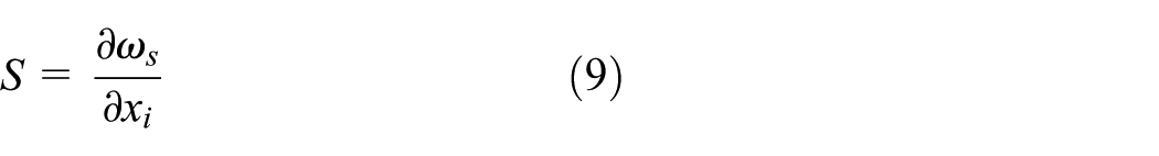
where S is the sensitivity of parameter,
To evaluate the parameter sensitivity, a parametric finite element model is built through using ANSYS Parametric design model. The effects of each parameter variable on the optimization frequency are shown in Figure 9. According to the weighted-sum theory, 18 with a larger baseplate mass, the force outputted by the vibrator will decrease because of driving the mass instead of the earth. Consequently, the mass of the supporting column is considered as a nonlinear constraint. The impacts of the parameter variables on the mass of the support column are also shown in Figure 9.

Effects of individual parameter variable on optimization frequency and mass.
As shown in Figure 9, with the increase in the
Response surface model
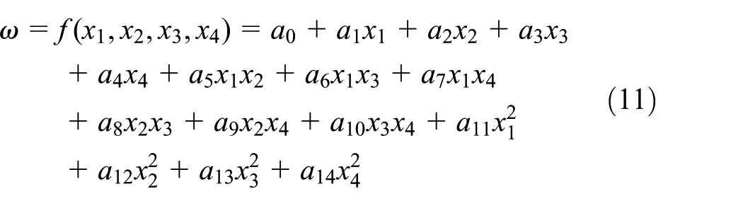
To analyze the effects of multiple parameters on the optimization frequency, a response surface was employed in the optimization process. 19 Response surface models are multivariate polynomial models, which can be given as
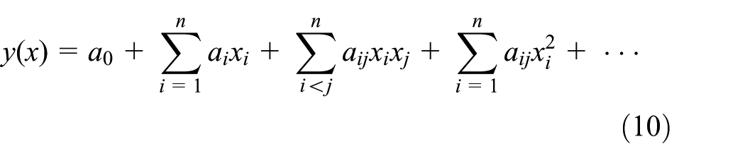
where
The number of sample points is an important influence factor which affects the accuracy of the response surface. Increasing the number of samples can bring about significant computational costs. Consequently, to generate adequate sample points and save time, central composite designs are used to design numerical experiments.
20
The sample sets of
Sample sets of optimization parameters in given range space.

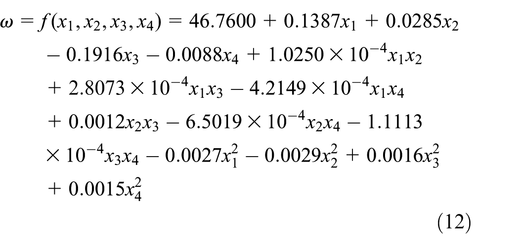
According to the design numerical experiment results in Table 3, a full quadratic response surface model can be employed to establish the function between the parameters and the swing natural frequency
where
In order to test the performance of the response surface model, the residual
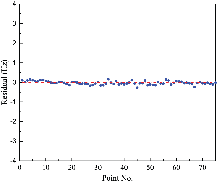
Residuals of the design points.
Optimization procedure
Parameter variation can bring about the change of mass and stiffness coefficients of the supporting column. With the optimization frequency being the objective and the mass being the constraint, the model of the optimization of the supporting column is demonstrated as follows

where
PSO algorithm is employed to solve the formulated optimization problem, which is based on the cooperative behavior among animals.21–23 The position of particles in the design space represents the potential solution of the optimization. Each particle updates its location according to its own best position and the entire swarm’s best position at each generation.
To solve the nonlinear constraint problem, a non-stationary penalty function is applied to transform the constraint into a series of unconstrained problems. The penalty function is given by

where
In the PSO, the velocity and position of the particle are updated by
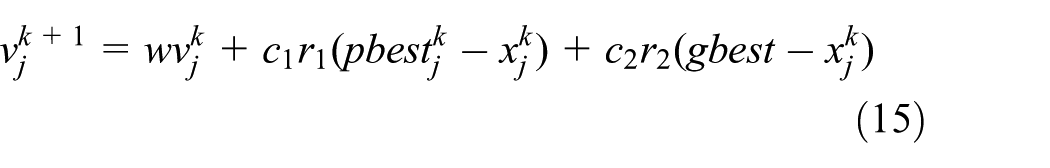
where

where iter is the current generation while itermax is the maximum generation.
The cognitive scaling parameter and the social scaling parameter also have effects on the performance of the PSO. 26 At the beginning of the evolution, the algorithm needs a stronger self-cognitive ability to move around and search space. However, a stronger social scaling parameter and a small cognitive scaling parameter are applied, which can lead the particles to converge to the global optimal solution. Thus, the scaling parameters are shown as

where
Due to the specific design spaces of the parameter variables, the probability of particles moving out of the feasible space grows with the increase in the dimensions. A boundary handing technique is used to avoid particles moving out of the feasible space. When the particle moves out of the boundary, the position and the velocity are set as


In conclusion, the main procedures of the modified PSO used to solve the formulated optimization mainly are as follows:
Step 1. Set the population size of the algorithm and randomly generate the initial positions and velocities of the particles.
Step 2. Calculate the penalty function of the particles based on equation (14), respectively. Establish the fitness function according to the objective and the penalty function.
Step 3. Calculate the fitness of the particles and update their positions and velocities based on equations (19)–(21).
Step 4. In order to maintain the diversity of the population, a mutation operator will be applied if the predefined stagnation criterion has been reached.
Step 5. Repeat the Step 2 to Step 4 until the predefined maximum generation has been reached.
The optimization problem has been defined by equations (12) and (13). After applying the PSO algorithm, the values of the parameters in the optimal solution along with the initial design are represented in Table 4.
The optimal solution.

Discussion of the optimization results
In order to verify the optimization, the finite element model of the vibrator is modified according to the optimization results. The harmonic response curves in the Y-direction of the optimization model and the original model are presented in Figure 11. The frequency of the biggest resonance peak of the optimization model is about 43.255 Hz, and the amplitude of the resonance peak is
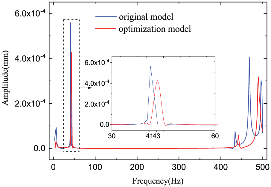
Comparison of the harmonic response.
Conclusion
In this article, an optimization combining response surface model and PSO algorithm has been used to optimize the dynamic stiffness of the seismic vibrator. To analyze the response of the vibrator, a modified finite element model with reaction mass is established. Through harmonic response analysis, the response of the vibrator in three directions is obtained. The frequency of biggest resonance peak is about 41 Hz in the Y-direction. Through modal analysis, the supporting column is found out as the weak link of the vibrator dynamic stiffness. Sensitivity analysis has been performed through employing a parametric finite element mode, and the effects of the parameters on the swing natural frequency of the supporting column is obtained. And, four parameters are chosen as optimization variables. Response surface model has been used to construct the objective function of the optimization, and the swing natural frequency predicted by the response surface model has good accuracy. PSO algorithm has been used to solve the nonlinear constrained optimization problem. And, the optimal solution is verified by the finite element model, which shows that the proposed optimization strategy is an efficient way to improve the dynamic stiffness of the vibrator.
Footnotes
Handling Editor: Jose Ramon Serrano
Declaration of conflicting interests
The author(s) declared no potential conflicts of interest with respect to the research, authorship, and/or publication of this article.
Funding
The author(s) disclosed receipt of the following financial support for the research, authorship, and/or publication of this article: This work was supported by the National High Technology Research and Development Program of China through the project of Development of the High Precision Vibroseis (grant no. 2012AA061201).