
Abstract
Electrical energy consumption is an important component of energy consumption for internal combustion engine vehicle, which directly affects the fuel economy. A bus-based electrical energy management system is built, and an electrical energy management strategy based on driving cycle recognition and electrical load perception is presented to achieve the refined management of vehicle energy. Six typical driving cycles are selected to establish an improved learning vector quantization neural network model for driving cycle recognition. The corresponding model training algorithm is designed by utilizing a similar driving cycle classification and the gradient optimization so that the better recognition accuracy and the less computation intensity can be obtained. An online recognition mechanism based on sliding time window is devised, and the optimal time window length is determined. To minimize fuel consumption, a dynamic optimal regulation strategy for the output power of the alternator and battery, which considers driving cycle recognition and electrical load perception, is proposed. Experimental results show that the strategy can effectually improve the vehicle fuel economy according to the driving cycle and the electrical load change and decrease the fuel consumption per 100 miles of vehicle.
Keywords
Introduction
Although hybrid electric vehicles (HEVs) and battery electric vehicles (BEVs) are developing rapidly nowadays, internal combustion engine (ICE) vehicles are still in the mainstream of the vehicle market because of the problem of technology and cost. With the increasing number of electronic control units (ECUs) and electrical loads, the proportion of electrical energy consumption in vehicle energy consumption is significantly increasing. Electrical energy management is to be considered for a better fuel economy. 1 However, ICE vehicle mainly adopts a static method for electrical energy management. When the vehicle is running, the alternator provides almost all powers of ECUs and electrical loads in the vehicle, while the battery hardly works for them. The actual output of alternator and battery cannot be dynamically adjusted to their appropriate point according to the driving condition and electrical load change. The more effective functions of energy management, such as battery protection, braking energy recovery is difficult to be implemented. Therefore, to reduce energy consumption and improve fuel economy of ICE vehicle, the real-time and dynamic strategy of electrical energy management is becoming a new trend in automotive companies and research institutions.2,3
Research on dynamic energy management was carried out earlier in HEVs and BEVs. Relevant research results provide a useful reference for ICE vehicles. S Onori et al. 4 presented an adaptation law of the equivalence factor used by equivalent consumption minimization strategy (ECMS) and used the feedback of state of charge (SoC) to ensure optimal energy control. Hu et al. 5 presented an online architecture with deep reinforcement learning (DRL) and applied the DRL algorithm in HEV energy management under different driving conditions. Mansour and Clodic 6 proposed an overall optimized predictive energy management strategy based on dynamic programming, which can predetermine the power split ratio and optimize the fuel consumption for the entire predicted route. Hanane et al. proposed a real-time control strategy for fuel cell/supercapacitor electrical vehicles by combining Pontryagin’s Minimum Principle (PMP) and Markov chain, which was used to predict future electricity demand during the driving cycle. The optimal control problem was formulated as an ECMS. 7 Hou et al. 8 designed a piecewise linear approximation method and proposed an optimal energy management strategy based on the approximate PMP algorithm for parallel plug-in HEVs. An energy management with multiple level controllers was proposed by Kamal et al. to minimize the total energy consumption in HEVs. The MATLAB/TruckMaker simulation validated the method.9,10 Chen et al. 11 presented an online correction algorithm for plug-in HEVs, which can reduce the deviation from energy control strategy by predicting future driving cycle. Xia et al. presented a single degree-of-freedom energy optimization strategy to reduce fuel consumption of power-split HEVs. It was dependent on a quadratic performance index and the limit on the fluctuation of battery SoC. 12
The previous energy management strategies for HEVs and BEVs can effectively improve vehicle fuel economy, but cannot be directly applied to ICE vehicles because of the different structures of electrical system. Due to the increasing consumption of electrical energy in a vehicle, several groups have studied the electrical energy management for ICE vehicles based on previous strategies. A comprehensive calculation method for the SoC of battery is proposed by Kong et al., 13 which can monitor the entire process of battery operation in real time and achieve battery loss protection. J Couch et al. 14 optimized the fuel economy under the constraints of the demand of electrical load, the limits on the battery SoC, and system voltage. Colin et al. presented a supervisory energy control strategy based on adaptive PMP. But the original alternator controller should be modified if it is applied into an ICE vehicle. 15 Furthermore, Wang et al. formulated electrical energy management as a global optimal control problem, which aims to minimize fuel consumption, and a PMP-based energy control strategy is proposed. The strategy dynamically regulates the output of the battery and alternator according to current electrical load and known driving cycle. 16 Taherzadeh et al. 17 proposed a novel and efficient on-off control strategy for ICE and used an optimization algorithm to find the optimal ICE operation region.
As mentioned previously, the electrical energy management strategies for ICE vehicles improve the vehicle fuel economy. However, these strategies depend on known driving cycles, whereas the real driving situation is often stochastic and different. This causes that the effectiveness of these strategies is not as good as expected. 18 The online recognition of real driving condition naturally is one of the good ways to fix the problem.
Feng et al. 19 applied the pattern recognition approach to identify the driving cycle and selected the control strategy and control parameters with the change of vehicle driving patterns. Reza et al. utilized a driving condition recognition to evaluate the driving environment, the driving mode, and so on. This information can be used to determine the power division, which affected the fuel economy and emissions. 20 Although these recognition methods are validated by experiments, these methods are relatively complex for the implementation in the embedded ECUs. Besides, the learning vector quantization (LVQ) neural network was introduced into the driving cycle recognition (DCR). Xing et al. 21 formulated an LVQ-based DCR method to recognize the real driving cycle, but the training samples and characteristic parameters are insufficient to guarantee recognition accuracy. He et al. 18 applied the principal component analysis and micro-trip extraction to the LVQ model to improve the adaptability of the model. Song et al. proposed a multi-mode energy management strategy for electric vehicles with a fuel cell range extender based on LVQ driving condition recognition. This strategy can automatically switch to the genetic algorithm for specific driving conditions in the light of the differences of condition recognition results. 22 However, the improvement of recognition accuracy was unsatisfactory.
For ICE vehicles, an electrical energy management system based on the bus structure is introduced in this article. To further improve the vehicle fuel economy, an improved learning vector quantization (I-LVQ) neural network model is proposed for the online DCR, and an electrical energy management strategy combining the DCR and the electrical load perception (ELP) is presented. The rest of this article is organized as follows: first, the electrical energy management system for ICE vehicles is discussed. Second, the DCR based on the I-LVQ neural network is presented in detail. Third, the online strategy in the electrical energy management system is depicted. Next, the corresponding experiments are described, and the results are analyzed. Finally, the conclusion is presented.
Bus-based electrical energy management system
As shown in Figure 1, the bus-based electrical energy management system for ICE vehicles consists of an energy management controller (EMC), an intelligent alternator, and an intelligent battery sensor (IBS). These parts communicate with one another by the local interconnection network (LIN) bus. The LIN bus is connected with the controller area network (CAN) bus by the gateway body control module (BCM). That makes the EMC obtain more real-time information from the engine management system (EMS) and other ECUs. 16

Electrical energy management system.
The IBS periodically collects the current and voltage of the battery and calculates the battery SoC. From the EMS to the EMC, the on-off state of electrical loads, the speed and torque of the engine are sent by the BCM in the LIN bus. The EMC performs the DCR online and dynamically regulates the actual output of the alternator and battery with the changes of the driving condition and electrical loads. This operation helps maintain the battery in a better state and reduce fuel consumption and exhaust emission.
DCR based on the I-LVQ neural network
Driving cycles and characteristic parameters
The main task of the DCR is to match the real driving cycle with a typical driving cycle. In this article, six typical driving cycles are considered and listed in Table 1.
18
These cycles are denoted as the set
Typical driving cycles.

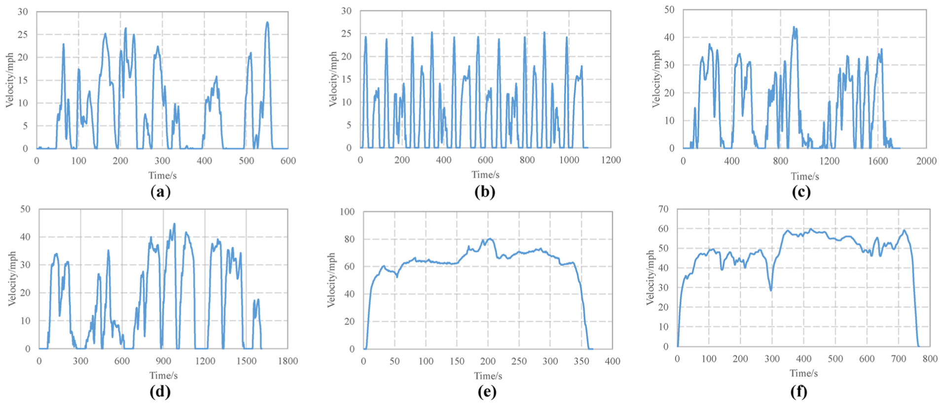
Velocity–time curves of the typical driving cycles: (a) NYCC, (b) MANHATTAN, (c) CSHVR, (d) WVUSUB, (e) US06_HWY, and (f) HWFET.
As shown in Figure 3, the interlacing partition of unequal length is employed to determine the recognition samples in order to reduce the adverse effect caused by the similarity between six typical driving cycles on the DCR. For each
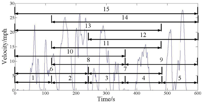
Partitioning illustration of the typical driving cycles.
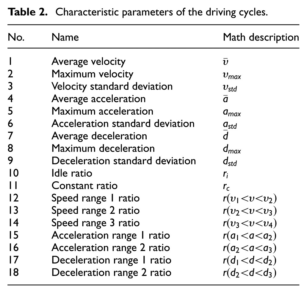
For convenient calculation, 18 characteristic parameters are extracted to describe the features of driving cycles fully, as listed in Table 2.
23
These characteristic parameters for each
Characteristic parameters of the driving cycles.
DCR model based on the I-LVQ neural network
The LVQ neural network is a class of algorithms for pattern recognition and has been widely used in DCR. 21 However, the LVQ neural network cannot easily obtain ideal recognition accuracy and low computational complexity when the sample space is relatively large. 24 Therefore, an I-LVQ neural network is considered and applied to recognize driving cycle online.
The DCR model based on the I-LVQ neural network, which is composed of an input layer, competitive layer, and output layer, is shown in Figure 4. X represents the input vector, which is the standard characteristic parameter vector of the driving cycle to be recognized;
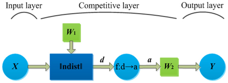
DCR model based on the I-LVQ neural network.
Generally, the recognition accuracy and training time of the LVQ neural network depend on the model training process. However, the similarity between 90 recognition samples in the set
Definition 1
The probability of

Definition 2
For

then
Obviously, the smaller the probability defined in Definition 1, the less likely the sample

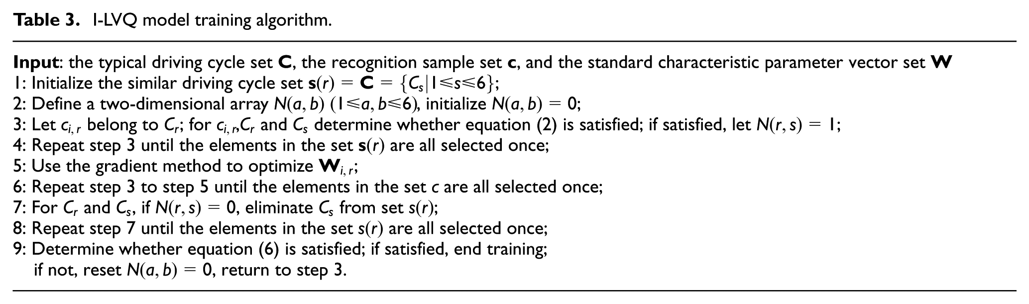
I-LVQ model training algorithm.
The set

Recognition samples should satisfy equation (3) to reduce the error recognition rate and the difference between
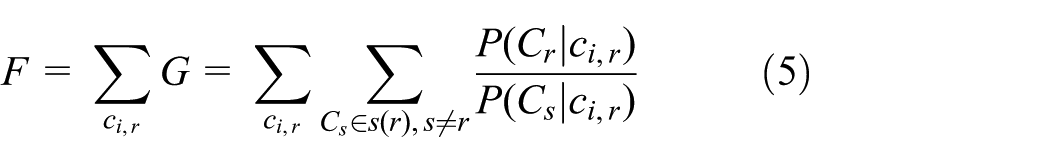
The gradient optimization method 25 is applied to optimize the DCR model. The training direction is to make the value of function F as large as possible. Training ends when

is satisfied.
The I-LVQ model training algorithm is shown in Table 3. In the process of model training, parameter optimization is performed only in the similar driving cycle sets, which are constantly updated. The number of elements in similar driving cycle sets continues to decrease, whereas the recognition accuracy of the model is improved. Training ends when equation (6) is met.
As shown in Figure 5, a comprehensive driving cycle which is originated from the six typical driving cycles shown in Table 1 is employed as the test driving cycle, 18 namely, US06_HWY + MANHATTAN +WVUSUB + HWFET + CSHVR + NYCC. The I-LVQ and LVQ algorithm 21 are used to train the DCR model to verify the effectiveness of the model training algorithm. Each 200-s time length of the comprehensive driving cycle is considered the recognition target. The training time and recognition accuracy are compared under the two model training algorithms.

Velocity–time curve of the comprehensive driving cycle.
Table 4 presents the comparisons of the training time and recognition accuracy of the DCR model under the two model training algorithms. Notably, the recognition accuracy is improved as the training time decreases when using the I-LVQ algorithm to train the DCR model. The accuracy improving rate is 3.3%.
Comparisons of training time and recognition accuracy under different training algorithms.
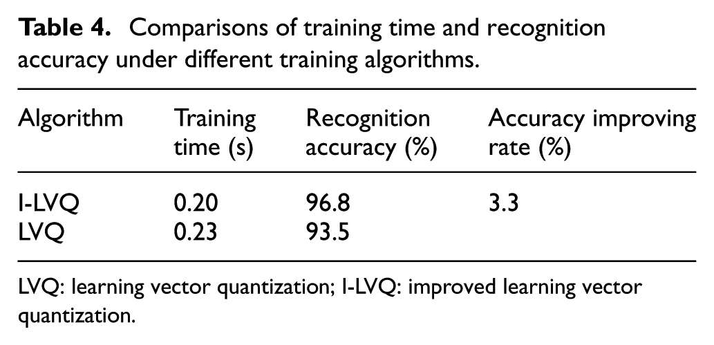
LVQ: learning vector quantization; I-LVQ: improved learning vector quantization.
Receding-horizon design
In the actual DCR process, in addition to the training algorithm of the model, the recognition accuracy is also related to the recognition frequency. A sliding time window is designed in this study, as shown in Figure 6, to periodically recognize the real driving cycle

The mechanism of sliding time window.
In Figure 6, the current time is
Determining the ideal time window length

Comparison of recognition accuracy under different time window lengths.
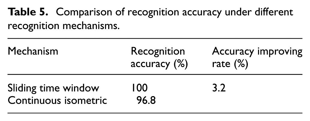
Table 5 presents the contrast of recognition accuracy under the sliding time window mechanism
Comparison of recognition accuracy under different recognition mechanisms.
Vehicle electrical energy management strategy based on the DCR and ELP
Problem definition
For ICE vehicles, the electrical energy management aims to achieve better fuel economy and improve the dynamic characteristic. A reasonable regulation of the alternator output power can help to realize this target with the changes of the driving condition, electrical load power, and battery SoC. Considering the relationship between the output voltage and the output power, the EMC should dynamically regulate the alternator output voltage. The corresponding regulation of the alternator output voltage is shown in Table 6. When the vehicle accelerates, the alternator output voltage should be lowered or even set 0 V to improve the vehicle dynamic characteristic. When the vehicle decelerates, the alternator output voltage should be heightened to recover and store part of the kinetic energy during braking through charging the battery. When the vehicle is running at the constant speed or idle speed, the alternator output voltage should be dynamically adjusted according to the electrical load power and the battery SoC.
Regulation of the alternator output voltage.
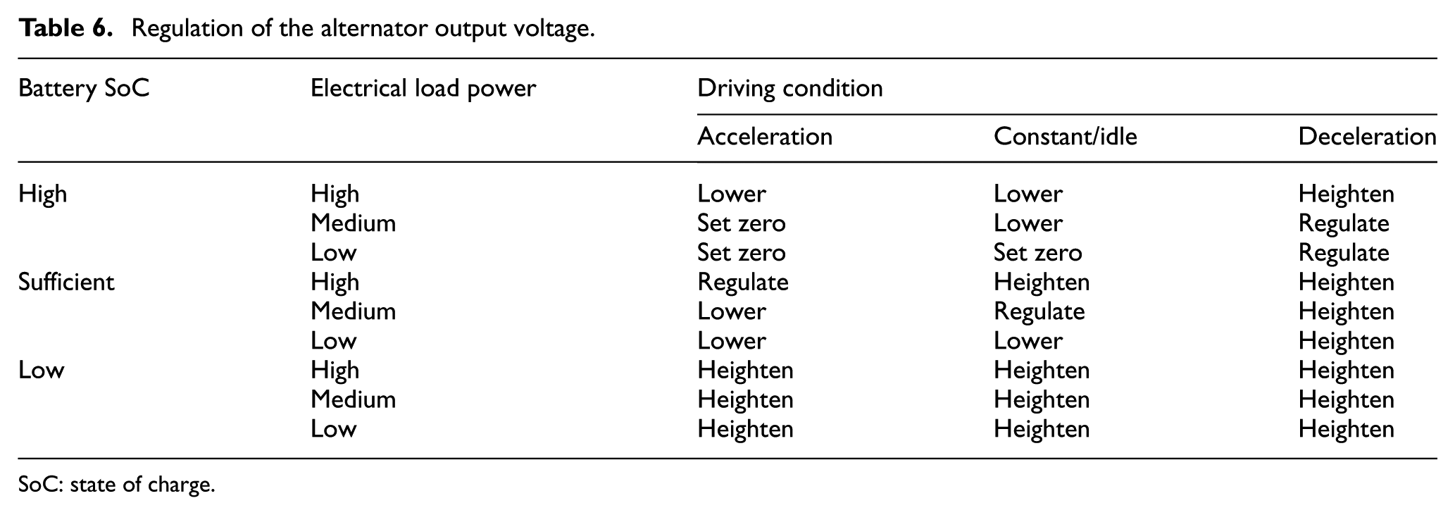
SoC: state of charge.
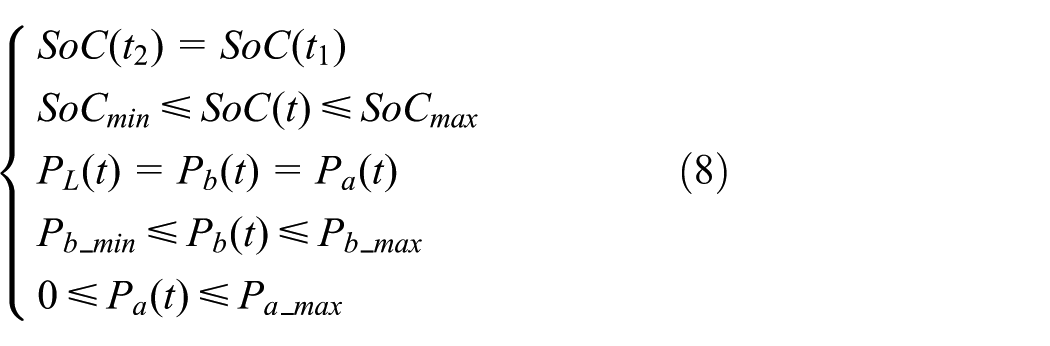
In order to realize the above regulation of the alternator output voltage, the electrical energy management problem of the electrical system of the ICE vehicle can be simplified as a constrained global optimal control problem with a single degree of freedom within

where
To avoid over-charging or over-discharging the battery and guarantee the comfort and safety of the driver, the battery SoC, the alternator output power, and the battery power should be restricted as 28
The constrained global optimal control problem mentioned above can be approximated as a local optimal problem within

where
If
The costate
The battery power interval when the electrical load power is

Online electrical energy management strategy with ELP
For a given
Electrical energy management algorithm with ELP.

ELP: electrical load perception.
Online electrical energy management strategy with DCR and ELP
Considering the DCR method based on the I-LVQ neural network and the online electrical energy management strategy with ELP, an online electrical energy management strategy based on the DCR and ELP can be established, the flowchart of which is shown in Figure 8. The I-LVQ DCR model is built and then trained by using the I-LVQ model training algorithm. The sliding time window is applied to recognize the T-in-length real driving cycle
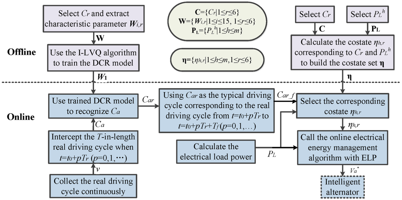
Flowchart of electrical energy management strategy with DCR and ELP.
Experimental results and analysis
Several vehicle experiments are conducted to verify the online electrical energy management strategy based on the DCR and ELP. Some core parameters of the ICE vehicle in the experiments are listed in Table 8.
Vehicle parameters in the experiments.

A total of three vehicle experiments are conducted in this study, namely, the experiment without electrical energy management strategy, the experiment for the online electrical energy management strategy with ELP, and the experiment for the online electrical energy management strategy with DCR and ELP. The comprehensive driving cycle shown in Figure 5 is chosen as the test driving cycle and the electrical load power is constant for all the experiments.
The experiment without electrical energy management strategy
Figure 9 presents the experimental results when no electrical energy management strategy is utilized. As shown in Figure 9(a), the alternator output voltage remains stable at approximately 13.9 V and only fluctuates slightly as the electrical load power changes. As shown in Figure 9(b), the battery maintains charging, with the battery SoC increasing consecutively after the vehicle is started. As indicated in Figure 9(c), the battery charging power remains stable at approximately −275 W, which is always equal to the difference between the electrical load power and the alternator output power.

Experimental results without strategy: (a) alternator output voltage, (b) battery SoC, and (c) power change contrast.
The experiment for the online electrical energy management strategy with ELP
The driving cycle is not recognized in this experiment. The corresponding experimental results are shown in Figure 10. Figure 10(a) demonstrates that the alternator output voltage fluctuates intensively after applying the electrical energy management strategy with ELP. Figure 10(b) shows that the fluctuation range of the battery SoC is restricted during this experiment, where the frequent charge–discharge process indicates the active participation of the battery in power supply. Figure 10(c) presents that the electrical load power equals to the total of the output power of the battery and alternator, with the utilization rate of the battery significantly increased.

Experimental results with ELP: (a) alternator output voltage, (b) battery SoC, and (c) power change contrast.
The experiment for the online electrical energy management strategy with DCR and ELP
The driving cycle is recognized during this experiment. Figure 11 shows the corresponding experimental results. As shown in Figure 11(a), the fluctuation intensity of the alternator output voltage has increased after the DCR, which reflects the improvement in the efficiency of load power allocation. As indicated in Figure 11(b), the battery SoC varies more regularly with the decrease in the corresponding fluctuation range, which illustrates that the working status of the battery has been optimized. As demonstrated in Figure 11(c), the fluctuations of the battery power are very frequent. But the total output power of the battery and alternator also equals to the electrical load power.

Experimental results with DCR and ELP: (a) Alternator output voltage; (b) Battery SoC; (c) Power change contrast.
The contrast of fuel consumption under the three vehicle experiments is shown in Table 9. Compared with the scheme without electrical energy management strategy, the vehicle fuel consumption per 100 miles is decreased by 0.20 L when utilizing the online electrical energy management strategy with ELP, with the fuel saving rate of approximately 1.4%, and the vehicle fuel consumption per 100 miles is reduced by 0.23 L when applying the online electrical energy management strategy with DCR and ELP, with the fuel saving rate of approximately 1.6%. Accordingly, the vehicle fuel economy is, respectively, improved after implementing the DCR and ELP.
Comparison of fuel consumption under the three experiments.
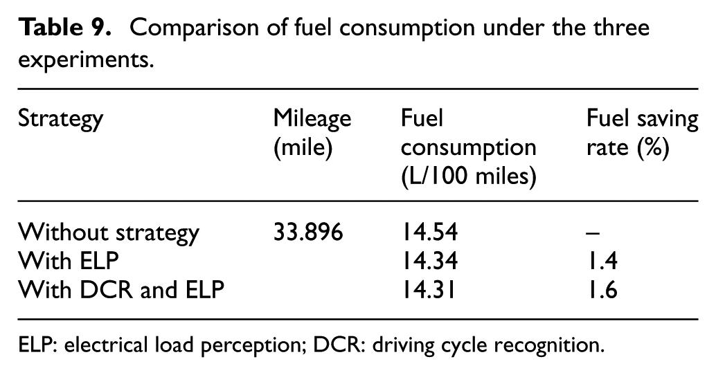
ELP: electrical load perception; DCR: driving cycle recognition.
Conclusion
In this article, for ICE vehicles an electrical energy management strategy based on the DCR and the ELP is presented with the corresponding bus-based electrical energy management system. For higher recognition accuracy and less computational complexity, an I-LVQ DCR model and a recognition mechanism of sliding time window are proposed for the DCR, respectively. They also help to reorganize the real driving conditions of ICE vehicles online. Compared with the previous method, this strategy can dynamically adjust the output of the alternator and the battery with the change of electrical loads and real driving conditions. Therefore, it can better improve the vehicle fuel economy. In future, the influences of driving cycle partition and characteristic parameters selection on the recognition accuracy and computational complexity will be further studied so that the strategy can be easily implemented in vehicles.
Footnotes
Handling Editor: Fakher Chaari
Declaration of conflicting interests
The author(s) declared no potential conflicts of interest with respect to the research, authorship, and/or publication of this article.
Funding
The author(s) disclosed receipt of the following financial support for the research, authorship, and/or publication of this article: The authors would like to acknowledge the support of the National Natural Science Foundation of China (61202096) and the National Natural Science Foundation of Anhui (1708085MF157). This work was also supported by the STSP of Anhui (15czz02039). The authors are also grateful for the sponsorship from projects of Jianghuai Auto and SOTECH Auto-Electronic (W2016JSKF0394, W2016JSKF0454, W2016JSKF0554, and W2018JSKF0308).