
Abstract
Bayesian operational modal analysis and modal strain energy are employed for determining the damage and looseness of bolted joints in beam structures under ambient excitation. With this ambient modal identification technique, mode shapes of a damaged beam structure with loosened bolted connections are obtained based on Bayesian theory. Then, the corresponding modal strain energy can be calculated based on the mode shapes. The modal strain energy of the structure with loosened bolted connections is compared with the theoretical one without bolted joints to define a damage index. This approach uses vibration-based nondestructive testing of locations and looseness of bolted joints in beam structures with different boundary conditions by first obtaining modal parameters from ambient vibration data. The damage index is then used to identify locations and looseness of bolted joints in beam structures with single or multiple bolted joints. Furthermore, the comparison between damage indexes due to different looseness levels of bolted connections demonstrates a qualitatively proportional relationship.
Keywords
Introduction
Structures often suffer issues of accumulated damages due to changes in loadings and deterioration from age or environmental factors. Damage detection is therefore a key step in structural health monitoring. 1 Assessment of the state of a structure has been conducted by using either direct visual inspection or experimental techniques such as acoustic emission, ultrasonic check, and magnetic particle inspection to avoid causing destruction or influences to structural operation. 2 A characteristic of all these local methodologies is that they require a priori localization of damaged zones and lack practicability for large-scale structures.
These limitations can be resolved by using vibration-based (VB) methods, which can give a global damage assessment. Bayesian operational modal analysis (BOMA)3–10 is more convenient than experimental modal analysis (EMA) or conventional operational modal analysis (OMA) methods because it can process the response histories at all the measured degrees of freedom (DOFs) and only one set of response time histories is required.3,4 Moreover, it has good robustness against noisy measurement data because it uses directly calculated fast Fourier transform (FFT) results without the need of smoothing or averaging data.5,6 Thus, such method gives a great implication for the economy and convenience to identify dynamic responses of structures under their actual working situations. And the identification accuracy of the global damage can be validated.
Nowadays, many structural damage identification methods based on dynamic responses and dynamic parameters, including model updating methods, neural network methods, sensitivity-based methods, and damage index (DI) identification methods, 11–20 have been developed by comparing vibration information before and after damages to determine structural damage locations as well as assessing damage levels. Among them, DI identification methods are of increasing interest because they do not need to solve structural parameters by inversion but directly use vibration characteristics. Such methods only involve simple calculations and easy implementations and, hence, can generally satisfy requirements of monitoring systems.
In this work, the BOMA and modal strain energy (MSE) methods are used for identifying the locations and looseness of bolted joints in beam structures with different boundary conditions under ambient excitation. Advantages of the BOMA and MSE methods are integrated in this work. Modal parameters of beam structures with bolted joints before and after damages are determined by the BOMA method under ambient excitation. Then, by using mode shape curvature to obtain MSE, the DI can be obtained to identify locations and looseness of bolted joints in beam structures with single or multiple bolted joints. Furthermore, the comparison between DIs due to different looseness levels of the bolted connections demonstrates a qualitatively proportional relationship.
BOMA
Let

where

with
In Bayes’ theorem, the posterior probability density function (PDF) of

where

For convenience, the negative log-likelihood function

where
MSE
Physical damages of structures can cause changes to their dynamic characteristics. The vibration parameters employed in the identification of damages include the natural frequency, mode shape, damping ratio, mode shape curvature, MSE, and the flexibility matrix Generally speaking, structural damage would reduce the stiffness, increase the damping ratio, and change the information of the frequency and mode shape.21,22 The MSE method involving curvatures of the mode shapes has a good sensitivity in small structural damage identification and change of mechanical performance.14–16
For a Euler–Bernoulli beam, the strain energy can be expressed as

where x is along the direction of the beam length, y is the transverse displacement, EI is the bending stiffness, and

As the schematic diagram shows in Figure 1, grid points

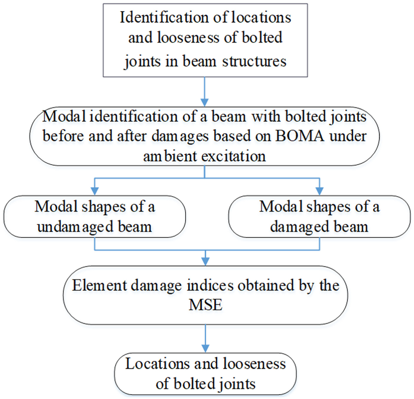
A flowchart of damage detection of a beam with bolted joints.
Obviously, the total MSE of the kth mode of the beam is

The summation of all fractional energies is

Considering all measured modes m, DI

and

where
Damage detection in beam structures
In order to simulate damages in a beam, bolted joints are used in this work. They can not only preset damage numbers and locations but also simulate different levels of looseness in bolted connections. Structures with bolted connections are wildly used in civil engineering. Damage detection of these structures, such as looseness localizations for bolted joints, is an important research topic.17–20 A flowchart of damage detection of a beam with bolted joints used in this work is shown in Figure 1 according to the abovementioned theoretical methods. The arrangement of n DOFs with a uniform distribution for a cantilever beam is shown in Figure 2. In each setup of the experiment, three DOFs are tested and the second DOF is selected as a reference. Only one-dimensional mode shapes (vertical direction) are considered here. Accelerometers are Kistler (8395A) with a sensitivity of

Arrangement of DOFs and measurement setups of the cantilever beam.

A single damage in the cantilever beam.
Physical parameters.

The identified natural frequencies and corresponding standard deviations obtained by the BOMA method for cases I–IV in Table 1 are listed in Table 2. The measurements were conducted according to different measurement setups according to Figure 2. And the results in Table 3 show very good consistency for different setups.
Results of identified natural frequencies with different measurement setups (Unit: Hz).
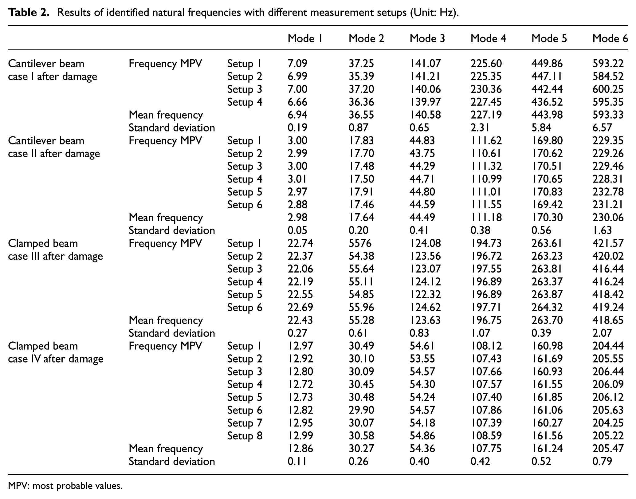
MPV: most probable values.
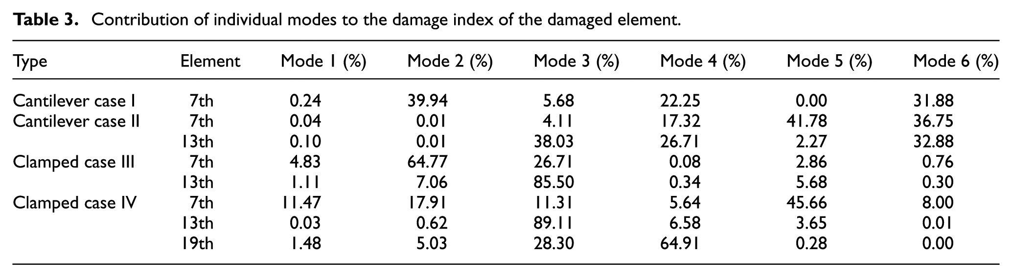
Contribution of individual modes to the damage index of the damaged element.
Cantilever beam with different damages
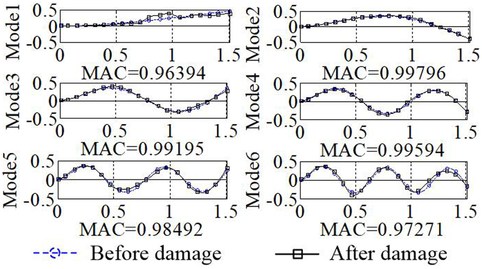
Cantilever beams with single damage (case I with a single bolted joint) and multi-damages (case II with multi-bolted joints) were detected here. Figure 4 shows the first six identified mode shapes of the cantilever beam with a single bolted joint before and after damages obtained by the BOMA and theoretical method, respectively, where
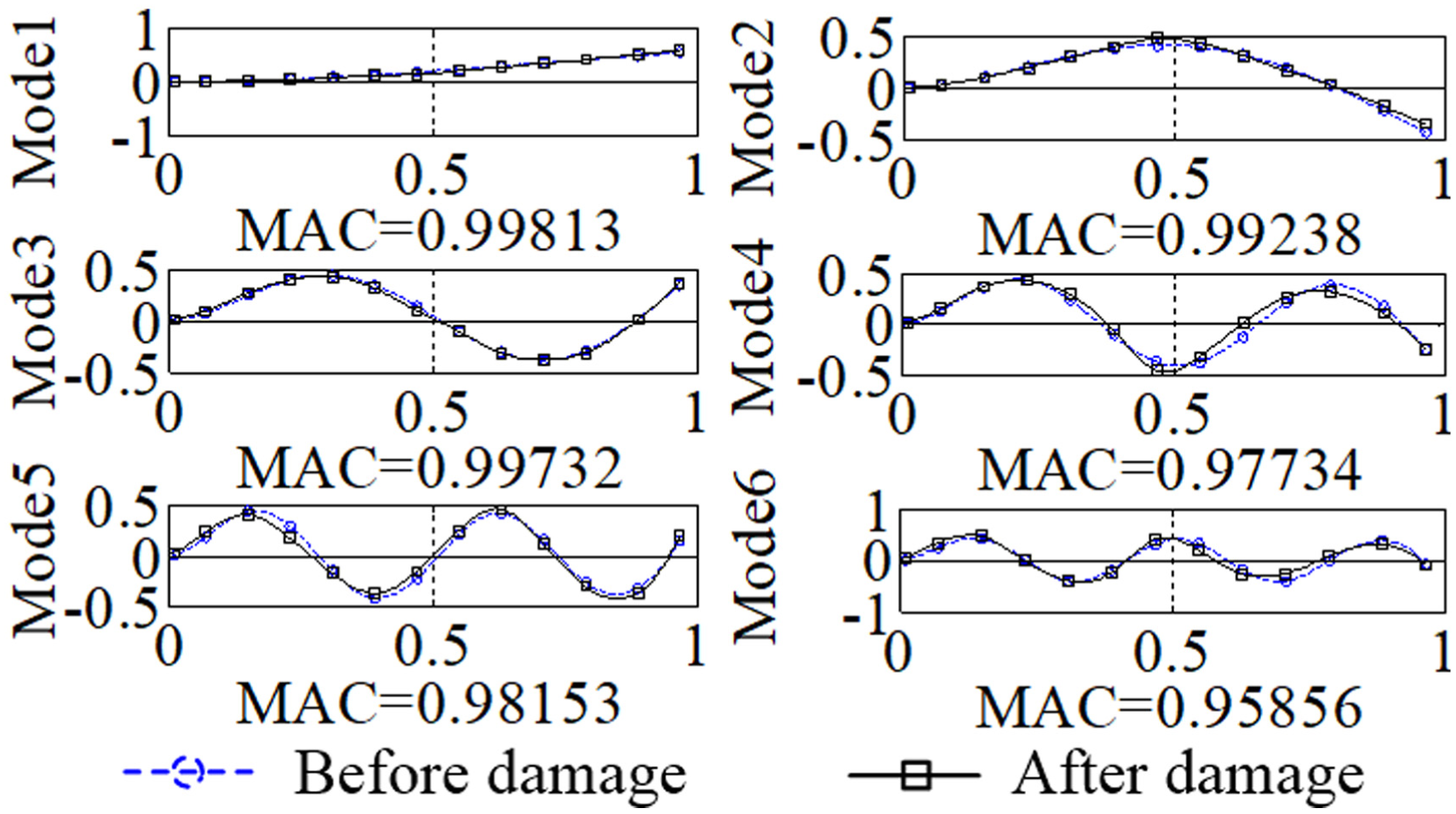
Mode shapes of the cantilever beam with a single bolted joint before and after damages (case I).
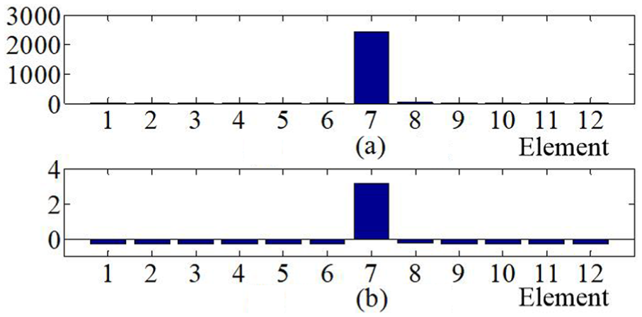
Element damage indices of the cantilever beam with a single bolted joint (case I): (a) damage index and (b) normalized DI.
Mode shapes of the cantilever beams with two bolted joints before and after damages (case II).

Element damage indices of the cantilever beam with two bolted joints: (a) damage index and (b) normalized DI.
Clamped beam with different damages
Two clamped–clamped beams with different damages simulated by bolted joints were studied in this section. In case III, three beams were connected by two bolted joints. In case IV, three bolted joints connected four beams. Physical parameters and the damage locations of the two clamped–clamped beams are listed in Table 1. For case III, Figure 8 shows the first six identified mode shapes of the clamped–clamped beam with two bolted joints before and after damages obtained by the BOMA and theoretical method, respectively. Moreover, the element damage indices of the clamped–clamped beam in Figure 9 point out the damage locations successfully. For Case IV of the clamped–clamped beam with three damages, damage indices in Figure 10 can be used to identify the three damage locations even if the MACs in Figure 11 are very close to 1. The results of the examination of the cantilever and clamped–clamped beams show that the values of DI of the cantilever beams are much higher than those of the clamped–clamped beams, which indicate that cantilever beams are more sensitive to structural injuries. Contribution of individual modes to the DI of the damaged element is defined as

Mode shapes of the clamped–clamped beam with two bolted joints before and after damage (case III).

Element damage indices of the clamped–clamped beam (case III): (a) damage index and (b) normalized DI.

Element damage indices of the clamped beam (case IV): (a) damage index and (b) normalized DI.

Mode shapes of the clamped–clamped beam with three bolted joints before and after damage (case IV).
Different looseness levels of bolted connections
DI was used to study different levels of looseness in the bolted connections of a cantilever beam with single damage and a clamped–clamped beam with multi-damages, as shown in Figure 12. Obviously, damage in Figure 12(b) is more severe than that in Figure 12(a), and hence, larger damage indices are expected. Figure 13(a) and (b) shows the DI for the cantilever and clamped–clamped beams, respectively. It can be found from Figure 13 that the damage increases with the increase in the looseness levels of the bolted connections and clearly the damage indices as well. Therefore, such methods indicate that there is a qualitatively proportional relationship between DI and damage levels.

Arrangement of the different levels of looseness in the bolted connections: (a) damage level 1 and (b) damage level 2.

Comparison results of element damage indices with different damage levels for (a) the cantilever beam and (b) the clamped–clamped beam.
Conclusion
Using a non-destructive ambient vibration test, modal parameters of beam structures with different damages were identified by the BOMA method. One fundamental difference between the BOMA method and conventional approaches is that BOMA involves no concept of stochastic averaging and no decision on what quantity to average. Moreover, the BOMA and MSE methods can be used to identify locations and looseness of bolted joints in beam structures with different boundary conditions under ambient excitation. As applications, damage identification for beams with single damage or multiple damages under different boundary conditions (cantilever and clamped) were studied successfully by using a few mode shapes of beams only. Experiments for different levels of structural damages were carried out, and comparison between DIs due to different looseness levels of the bolted connections demonstrated a qualitatively proportional relationship.
Footnotes
Handling Editor: Magd Abdel Wahab
Declaration of conflicting interests
The author(s) declared no potential conflicts of interest with respect to the research, authorship, and/or publication of this article.
Funding
The author(s) disclosed receipt of the following financial support for the research, authorship, and/or publication of this article: The work described in this paper was fully supported by the grants from the Shanghai Natural Science Foundation (Grant No. 17ZR1419800) and the Shanghai Science and Technology Innovation Fund (Grant No. 17060502600).