
Abstract
Business Process Model and Notation is known as a widely used standard for business processes modeling. However, its main drawback is that it lacks formal semantics, leading to some undesirable properties, such as livelocks and deadlocks, such that it creates models with semantic errors. In order to formally verify them, we need to transform it onto a formal language, for example, Petri nets. The approach proposed in this article is an extension of previous approaches stated in the literature by adding probability to gateways and time to transitions. The first aim is to transform the Business Process Model and Notation process diagram onto Petri nets automatically using a developed software package. The developed software package is capable of transforming the XML file of a Business Process Model and Notation process diagram into “m” files of a Petri net. The “m” files of the Petri net are then coupled with the General Purpose Petri Net Simulator (GPenSIM) for analysis in MATLAB. The second aim is to manually transform the Business Process Model and Notation process diagram using mapping figures onto Petri nets and then analyze it using Timed Petri Net Analyzer tools. The advantage of transforming a Business Process Model and Notation diagram automatically is that we can add time to transitions and probability to gateways. Furthermore, the simulation time can be checked using MATLAB.
Keywords
Introduction
The Business Process Model and Notation (BPMN) is a modeling tool for capturing business processes. Standard BPMN offers a power (ability) to figure out business procedures in a graphical representation. 1 It provides companies with the potentiality of interacting procedures in a typical mannerism and is widely used as a tool for business process modeling. In addition, for simplification and better understanding of collaborations and transactions between companies, graphical notations are used. This notation adopts elements from a number of previously proposed notations for business process modeling, including the XML Process Definition Language (XPDL) 2 and the activity diagrams component of the Unified Modeling Language (UML). 3 A BPMN process model is composed of activity and control nodes and can be connected in a random way.
Several organizations (BPMI, OMG, OASIS, etc.) have explained a sequence of different standards for designing, executing, and monitoring business processes. These standards can be used either separately or in combined mode conditional upon the compatibility between them. With respect to notations, BPMN and UML are widely used in present. BPMN offers several advantages over other notations. For example, integrated definition (IDEF),4,5 a family of modeling languages, does not have resource modeling and control capabilities and does not cover data objects that are a kind of resources for business process modeling. UML emphases on software models, whereas BPMN emphases on business processes.
However, BPMN shows even more semantic errors 6 as it combines graph-oriented features with other characteristics from many other resources, such as workflow (WF) patterns and business process execution language (BPEL). 7 These features include the message flow between processes and execution of sub-processes in multiple times. The wrong use of BPMN elements such as OR/XOR-join, AND-join, or an event that does not permit more than one outflowing arc, and so on, results in syntactical errors. The correctness of models, for instance, invalid flow or constructs can be found syntactically in lesser time using tools such as Intalio2 and BizAgi1. On the other hand, structural errors are usually found at the runtime as compared to syntactical errors that are found while designing using modeling tools. The structural errors such as wrong use of split and joins or incorrect combination of elements are hard to be identified at the runtime due to the absence of formal semantics of BPMN models. The ability to statically analyze a BPMN model has become a desirable feature for tools supporting process modeling in BPMN. It is found that semantic errors in a BPMN model that is occasionally built by a user can be detected using well-known verification techniques.
The efforts made to semantically analyze a BPMN model are hindered by uncertainties in it because of language complexity and specification of the standard. In order to formally verify a BPMN model, it is necessary to use a formal language, such as Petri nets. For example, Petri nets have found extensive applications to industrial systems such as deadlock analysis and solution,8–10 supervisory control,11–14 implementation 15 and scheduling,16–19 and fault analysis.20–23 As an important mathematical tool of discrete event systems,24,25 Petri nets are found to be the most suitable language to do such analyses due to the availability of many existing analysis tools. However, a mapping between BPMN and Petri nets can be defined for semantic analysis in order to check the correctness of a BPMN model.
Moreover, the addition of firing times to the transitions and probability appended to the exclusive, inclusive gateway, and event-based gateway will introduce an additional feature for modeling business processes. Firing delay is the amount of elapse time between the enabling and firing of a transition. Adding firing time to a BPMN diagram can be done by adding annotations as they do not have any effect on the model. Upon transformation, annotations are discarded and time will be added to the transitions. Hence, the associated transitions are timed transitions. In BPMN, probability can be added to the sequence flows of gateways and upon transformation into Petri nets, the probabilities are added for all the outcoming paths. Moreover, the statistical information is required for adding the probability. This statistical information can be useful for gateways, such that the probability of all the outcoming paths can be determined. For example, in online shopping website, availability of statistical information will help determine the client opening a typical product to be prompted for one of the related products.
Contribution of this work
BPMN is a widely used standard for modeling business processes. The current version BPMN 2.0 is quite comprehensive. However, a major drawback of BPMN is the lack of verification techniques. In this article, we aim at solving the problems found in the existing works26–33 by transforming BPMN onto Petri nets. Our approach integrates the ideas in previous works30–44 to present a novel method of transforming BPMN elements (i.e. events, gateways, activities, pools, connecting objects, and lanes) onto equivalent Petri net elements. The major contributions of this article can be stated as follows:
We propose a method for mapping a large number of subset elements in BPMN onto Petri nets.
We present two methods for mapping: an automatic method and a manual method. For the automatic method, we develop a software package that can transform an XML file of BPMN models onto “m” files of Petri nets.
We propose an addition of probability to the inclusive, exclusive, and event-based gateway. Moreover, time delays are added to the transitions.
Experimental examples show that the proposed method can transform a large BPMN model onto an equivalent Petri net model for analysis.
In transforming a large number of subsets of BPMN elements onto Petri nets, the following subsets are included: events, activities, gateways, artifacts, swim lanes, and connecting objects. Furthermore, the mapping can be done either manually or automatically. In the manual method, each element of a BPMN model is transformed into an equivalent Petri net element according to the mapping figures. The transformed Petri net is then analyzed in Timed Petri Net Analyzer (TINA). The automatic method fetches the XML file of a BPMN model and transforms it into an “m” file of Petri nets. The m file of Petri nets is fed into GPenSIM in MATLAB for analysis. In the transformation of the XML file of a BPMN model into an “m” file of Petri nets, time and probability are considered in this method. Finally, comparison of the number of elements in both the BPMN and its equivalent Petri net is provided. The time taken for simulating the obtained “m” file of the Petri net model in the GPenSIM tool is recorded to be low.
Article organization
The remaining of this article is organized as follows. Section “Literature review” introduces the background of both BPMN and Petri nets. The mapping of activities, events, gateways, and swim lanes onto Petri nets is discussed in section “Preliminary background.” Section “Mapping BPMN elements onto Petri nets” describes the development of the BPMN framework and its basic modules and introduces tools used for analysis. The experimental studies are done using two examples to demonstrate the proposed method in section “Development of BPMN framework for analysis.” Finally, related work is briefly discussed in section “Experimental studies” and section “Conclusion and future work” concludes this study and provides future research.
Literature review
In this section, we briefly review the languages other than BPMN which are transformed into Petri nets and the techniques used for analysis of business process models.
The execution and effective design of business processes are becoming progressively significant to present business organizations. The basic organization need is to constantly redesign its business processes on daily basis such that its operation practices are aligned with the change in business requirements, which has been acknowledged for decades. 45 It is vital that changes in business processes are understood well and then represented systematically such that their influences are clearly defined. In order to understand well, there is an utmost need to create business process models. 46 These models basically illustrate present or future organizational behavior in order to achieve several purposes, for instance, the monitoring and control of process execution. The fast-growing use of business process modeling necessitates that the activities should be carried out systematically in order to increase productivity, efficiency, and consistency. 47 During past decades, it was recommended to develop more systematic and flexible approaches to design business processes.48,49 Levitt was the first who pointed out the significance of business processes in 1960s, and later on, researchers such as Harrington, 50 Davernport, 51 and Hammer 52 promoted its new perspective. The rapid increase in popularity of business processes has brought forth a promptly growing number of modeling techniques, methodologies, and tools for its support. 53 Hence, the selection of precise technique has become quite complex due to availability of large range of approaches. The first step before constructing any model is to identify its use and the purpose to select the right technique.
Kettinger et al. 54 present an overview of methods, tools, and modeling techniques utilized in Business Process Reengineering (BPR). Although the authors neither provide detailed description of tools nor the techniques, it has been the starting point of research. Phalp and Martin 55 differentiate between two benefits of business process models: one for restructuring business processes and the other for software development. In the work by Phalp, 56 the former purpose is described by arguing that pragmatic approaches are typically concerned with understanding and capturing business processes, whereas rigorous paradigms are mostly utilized for analysis of the process. Furthermore, for the analysis of business processes, it is mandatory to have proper sophisticated mechanism that includes both functional and dynamic aspects than qualitative analysis of static models. The user requires a model that can provide more interaction such as simulation to analyze business processes. Hence, approaches that are easily understandable and have diagrammatic notation such as BPMN, EPC, BPEL, and YAWL are selected in order to represent business processes. 57 The languages which are used other than BPMN for transformation onto Petri nets are EPC, BPEL, and YAWL. The first modeling technique besides BPMN is Event-driven Process Chains (EPCs). The main constraints in it are functions, events, and logical connectors. 58 Events are transformed onto Petri nets as places, whereas functions are modeled by transitions. In this setup, the main drawback is that the set of connectors are limited.
An XML-based language, that is, BPEL, is used to define business processes within web services. The foremost objective of BPEL is the standardization of format, such that companies can work and communicate with each other using web services. It includes activities, partner links, and variables. The formal semantics for BPEL has been proposed by several groups, among them the existing approaches are relied on finite state machine,59,60 abstract state machine,61,62 and process algebras. 63 Most of the approaches do not provide provision to BPEL’s most important features such as compensation, fault, and event handling. However, Petri nets provide much wider aspect especially for computer-aided verification purposes. In the work by Hinz et al., 64 the authors considered Petri nets semantics for BPEL and established that the semantics is well suitable for computer-aided verification purposes. The study by Van Der Aalst and Ter Hofstede 65 developed a Yet Another Workflow Language (YAWL) based on WF patterns, where objects and tasks are used to model control flow aspects. The main advantage of YAWL is that it supports the following features: OR operations, AND operations, split and joint operations. For semantic analysis of a BPMN model, Dijkman et al. 26 focused on the control flow prospective only and did not include features such as artifacts, lanes, and pools. The study by Wong and Gibbons 27 used communicating sequential processes (CSP) as the formal language that can be semantically checked by a tool called FDR. 28 By this method, BPMN models are mapped onto CSP events, and processes and the relation between tasks are described via CSP events. The resulting CSP models are complex and their size is huge. Moreover, this mapping cannot preserve the structure of a BPMN model. In addition, no explanation is presented for how the errors of a BPMN model can be detected through CSP semantics.
Puhlmann and Weske 29 presented a tool to analyze business models statically. By their method, very few subsets of elements of BPMN are mapped onto calculus. The main feature of BPMN, that is, error handling, is ignored in it. Soundness can be checked by calculus expressions. Experimental studies show that this method cannot cope with large models (more than 10 nodes). Dijkman and Van Gorp 30 defined a subset of BPMN (Ver. 2.0) elements formally with regard to graph rewrite rules. They showed that execution rules formally defined in this method are simple because they can be stated graphically. Using graph rewriting tools, formal semantics can be directly used in execution of models which were created in the BPMN. The issue of their approach was that resource and data aspects are ignored, and the provided semantics is least suitable for verification of process correctness. Raedts et al.’s 31 study presented a BPMN model which is automatically transformed onto Petri nets and is analyzed using any of the following tools: Yasper, INA, LoLA, and Woflan. The Petri nets can be automatically transformed onto a process algebraic language (mCRL2). The limitations of this method include the following: (1) few elements (gateways) are formally defined in the transformation, that is, AND and XOR gateways and (2) the method ignores the use of time and probability to the transitions.
Ramadan et al. 32 proposed formal semantics for business process models by mapping BPMN onto Colored Petri Nets (CPN). The proposed mapping is then used for the validation of process models. Koniewski et al. 33 proposed the use of Petri nets and BPMN formalism for building the models of multimodal logistic chains. First, logistics operations related to business processes are defined and then are represented in BPMN. The model is transformed into several Petri net phases. After that, for every single net, a single phase of complicated multimodal logistic chain is defined. The proper union of these nets forms a simulation model. In the work by Wong and Gibbons, 41 BPMN semantics is defined using CSP and refinement procedure is defined for property checking. However, the work by Wong and Gibbons 41 does not display how the data are modeled and how to detect several sort of errors using CSP semantics. The study by El-Saber and Boronat 66 formulates a subset of BPMN in Maude but does not consider multiple instances and cancelation of sub-process. Furthermore, no tool was provided to automatically generate Maude description from BPMN models. Roa and colleagues67,68 illustrate an approach focusing on anti-patterns in order to verify a block-structured collaborative business model defined in UP-ColBPIP language. The proposed approach covers numerous complex control flows but it has limitation in identifying constructs such as sub-processes, cancelation of instances, data object, and dynamic multiple instances. Furthermore, it is claimed that their approach can be utilized for BPMN language as well. In the work by Kheldoun et al., 69 formal semantics of BPMN is proposed using recursive Petri nets and rewrite logic. In the obtained formalism, a large number of subsets of BPMN elements including multiple instantiation, cancelation of sub-processes, and exceptional behaviors are covered, by which Maude LTL model checker can be used to verify behavioral properties of BPMN processes.
Preliminary background
In the section, we will briefly discuss BPMN and Petri nets.
BPMN
BPMN offers a graphical representation for modeling business processes. It is somehow similar to the UML. It was first implemented in 2006 by Object Management Group, and its latest version is 2.0. It is a kind of languages with a huge pool of object types to denote features of business processes, including control flow, resources, data, and exceptions.
BPMN is generally designed for exhibiting business processes at the theoretical level. Several categories of elements in BPMN exist. Flow objects, Swim lanes, connecting objects, and artifacts are among them. There are many types of elements in each category. Flow objects are used to represent the control flow features of a business process with three types of elements, that is, activities, gateways, and events. Moreover, control flow objects can be connected via sequence flows, and directed arcs are used to connect two objects for indicating the control flow.
The set of events in BPMN is shown in Figure 1 and is briefly introduced as follows. A start event presents the start of a process, while an end event specifies the ending of a process. An intermediate event indicates the occurrence of an event during a process. A message event is triggered when a message is received. A timer event is triggered when a particular date or time is reached. Finally, an error event is started when an error is detected during a process.
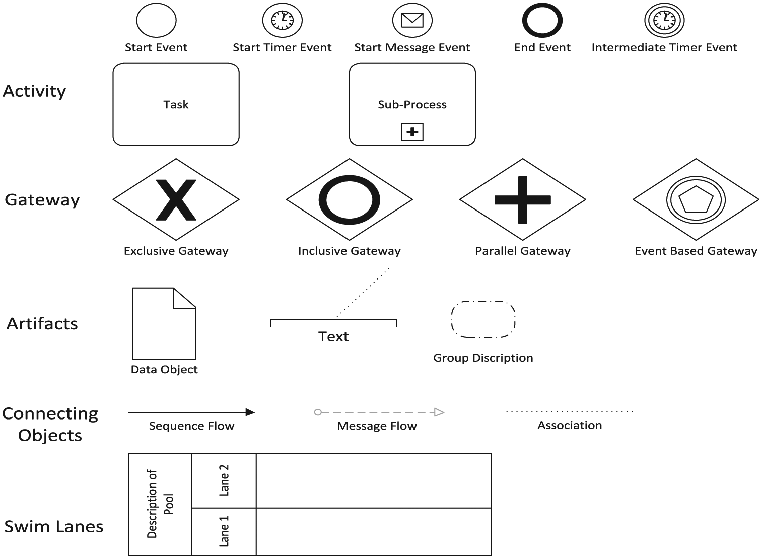
BPMN elements.
There are two types of activities: tasks and sub-processes. A task is modeled as an activity when a work is going to be performed within a process. A sub-process is composed of multiple tasks and there is a flow between these tasks. Gateways are used to model merging and diverging of sequence flows. An exclusive gateway indicates that only one outbound sequence is performed. Its purpose is to join several diagrams into one or divide one into several. A parallel gateway presents the outbound activities that are performed in parallel. More than two output flows are modeled via complex gateways.
BPMN elements are connected with each other via flows. Messages are exchanged between different pools via message flows, whereas control flow objects are linked through sequence flows. Artifacts are linked with each other via associations. Different members are disjointed from each other with a pool. An organization is usually represented by a pool. It can either be empty or have some processes. Lanes split activities in a pool from each other. Artifacts in a BPMN model are used to present new information to a user. Data objects are one of the artifacts which are used for displaying information. Basically, they do not affect the process but instead they provide extra information to the operator. Group does not have any effect on a process either and is used to categorize similar activities into a group. Finally, annotations deliver extra information to a user. BPMN is implemented in many software tools, among which are Oracle BPMN studio, 70 Intalio, 71 Signavio Process Editor,72,73 and so on.
Petri nets
The old-fashioned control theory works for time-driven systems, that is, systems of synchronous and continuous discrete variables, modeled by difference or differential equations. Due to an extension in the scope of control theory into the areas of robotics, manufacturing, communication and computer networks, there is an increasing demand for several models having the capability of describing systems that evolve in accordance with the abrupt occurrence, at possibly unknown irregular intervals of physical events. Such systems whose states are symbolic or logical, instead of numerical values that vary in reaction to events, are called discrete event systems and their corresponding models are called discrete event models.
As a mathematical and graphical tool for modeling DEDS (discrete event dynamics systems), Petri nets are suitable for modeling concurrent systems. 74 Petri nets have found their extensive applications to supervisory control of discrete event systems75–78 and further in previous works.79–81 This feature makes Petri nets a successful candidate for defining semantics of BPMN models in a formal way. Theoretically, Petri nets have become quite strong since numerous tools have been established for their analysis during the past several decades.
A Petri net is a bipartite-directed graph composed of places and transitions, where arcs are used to connect a transition to a place or vice versa, but it is not possible to connect the same type of nodes, that is, transition to transition, or place to place. Places are usually represented by circles and transitions are represented as rectangles. Tokens are placed in places and tokens represent the things that will flow through the system.
Definition 1
A Petri net is a 4-tuple
P and T are finite sets of places and transitions, respectively.
Flow relation
V is a weight function:
Basic elements of a Petri net contain places, transitions, and arcs. Place p is said to be an input place of transition t if there is a directed arc from p to t. Place p is said to be an output place of transition t if there is a directed arc from t to p.
Definition 2
A marking of Petri net
Definition 3
A marked Petri net is a tuple and is denoted as
Definition 4. (WF nets)
A Petri net
N includes two distinct places
If a transition
In our case, we focus on an important consistency property called n-soundness. It means the proper termination of the n-cases execution and the lack of tasks or conditions which do not contribute to the processing of cases.
We denote the initial markings as
Definition 5. (Soundness)
A WF net

For all states

The last state is the only reachable state starting from the initial state with n tokens in place

Finally, there should be no dead transitions in
Mapping BPMN elements onto Petri nets
BPMN and Petri nets are completely different standards. The former lacks proper semantics, whereas the latter includes proper semantics that is helpful in analyzing BPMN diagrams. A BPMN process has the following characteristics: (1) a start event has no incoming flow and a single outgoing flow, (2) an end event has no outgoing flow but can have multiple incoming flows, (3) events and activities have multiple input flows and multiple output flows, (4) a decision or fork has precisely single incoming flow and more than one outgoing flow, and (5) a merge or join gateway has more than one input and a single output.
Event mapping
Anything that occurs during a sequence of a business process is called an event. It can be referred to as a trigger or a result. They are centered on where they happen in a business process. An event can occur at the start of a process, middle, or at the end of a process. A token is generated when a start event is being triggered in a new process. A token is consumed when an end event signal appears and this token sinks under such a condition. In Figure 2, the mapping between a subset of events onto Petri net is given. A start event is mapped onto a Petri net containing two places and a transition. For an end event, we cannot simply just do the transformation as shown in the mapping in Figure 2. Three special cases of end events are shown in Figure 3: a) all sequence flows come to one end event; b) there are numerous end events and each of them has one incoming sequence flow; and c) the combination of Cases 1 and 2. If we simply use the transformation given in Figure 2 for an end event, we are not able to decide which case occurs. To solve this problem, we use a separate end event for each task. Hence, there is a single transition and single place for each sequence flow as in Figure 4.
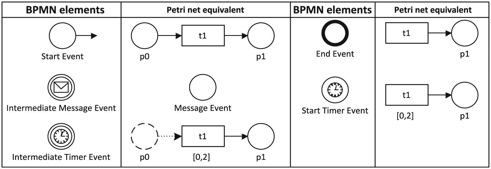
Mapping of events onto Petri nets.

End event cases.

Solution to the end event problem.
If we simply use the transformation given in Figure 2 for an end event, we will not be able to decide which case occurs. To solve this problem, we use a separate end event for each task. Hence, there is a single transition and single place for each sequence flow as shown in Figure 2.
A timer event is mapped onto a Petri net using a transition and a place. Here, the transition should be associated with time, that is, the initial time and final time. At the initial time, the transition may or may not fire, but it is supposed to fire at the final time. An intermediate event is triggered when a message is received and it is transformed onto a Petri net using a single place.
Activity mapping
Tasks are found to be the most essential process elements, which show work in a process. In BPMN, a task indicates an atomic activity which is contained within a process. Sub-processes are used when the activity can be further decomposed. For our purpose, we map task and sub-process onto Petri nets as a single transition and a place as depicted in Figure 5.

Mapping activities onto Petri nets.
For a task or a sub-process without any cycle, we can simply transform it onto a Petri net as shown in Figure 5. However, if there is a cycle in case of tasks as shown in Figure 6, we cannot simply do so.

Case of task or gateway having cycles.
A demonstration is given in Figure 7. If a task with a cycle is transformed simply using the method given in Figure 5, a deadlock occurs, that is, task

Transformation of a task or gateway having cycles.
Notice that Task

Recommended method to solve the cycle problem.
Gateway mapping
There are four types of gateways for mapping onto Petri nets: inclusive gateway, parallel gateway, data based exclusive (XOR) gateway, and event-based gateway. Exclusive gateway is an alteration point of a business process. For instance, if there are many paths in a process, only one path can be taken among many paths. Inclusive gateway is also a partition point and it may trigger more than one outgoing paths but no substance that all outgoing conditions have satisfied or not. A parallel gateway is used when there is an execution of concurrent activities. In this situation, when the process arrives at fork of parallel gateway, tokens are split into multiple tokens and merged when it reaches at joining parallel gateway. Event-based gateway is somehow similar to exclusive gateway but the trigger of the gateway is triggered by third party, that is, message sent by the costumer or intermediate timer event. Mapping of gateways onto Petri net is shown in Figure 9. The probability can be added to exclusive, inclusive, and event-based gateways. The probability for exclusive and event-based gateways can be found using the property

Mapping of gateways onto Petri nets.
Swim lanes
The frequently used element in BPMN is the swim lane which includes pools and lanes. A BPMN pool characterizes a contributor who contributes in a process. It is a rectangular package that can comprise flow object tasks and sub-processes. A lane is also a rectangular package, a sub-partition in a pool, where activities of a process are categorized and organized. The main functionality of a swim lane is to assembe a set of elements into a single unit. It does not have any impact on the WF. Hence, to transform a swim lane onto a Petri net, we simply convert it into different layers as depicted in Figure 10. Our developed software package is not capable to transform it into Petri nets as GPenSIM is not a graphical tool, but in the manual transformation, we can transform it as separate layers for each lane as depicted in Figure 10.
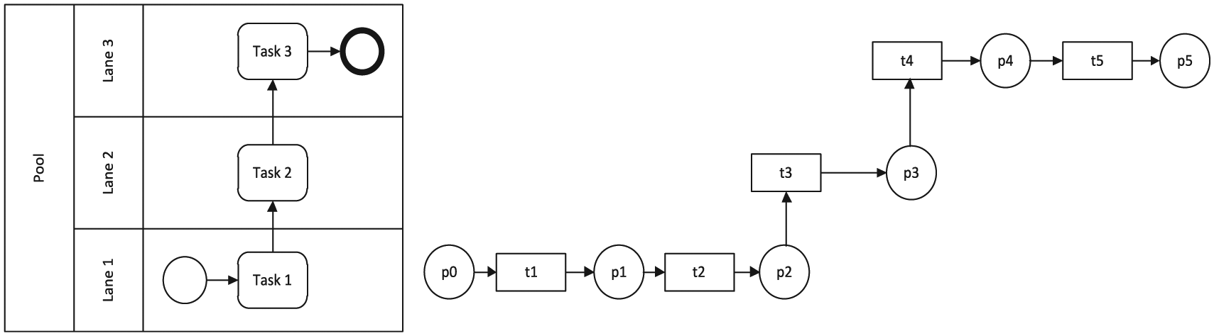
Mapping of swim lane onto Petri nets.
Development of BPMN framework for analysis
Based on the above transformation, we can discuss how to analyze a BPMN model. In the process of doing it, we present a framework. A block diagram as shown in Figure 11 is used to illustrate the framework. A BPMN diagram is created in Signavio Process Editor.72,73 Then, there are two ways for transformation, that is, automatic and manual ways. By the former, an XML file from Signavio Process Editor is downloaded and inserted into a developed software package, where the BPMN process diagram is transformed onto Petri nets by creating “m” files. Afterward, these “m” files are used in MATLAB for analysis. By the manual way, the transformation from a BPMN model onto Petri nets is done manually using the mapping figures and then its analysis is done using TINA. First, the manual method can be used for a small-sized BPMN model having less complexity, while the automatic method can be implemented for large complex BPMN models without requiring any human effort involved in mapping. Second, the manual method can also be used to compare the results obtained by GPenSIM because GPenSIM is not a graphical-oriented tool. Figure 11 shows the assembly that is employed.

Task execution diagram.
Step-by-step procedure of analysis using GPenSIM (automatic path) is as follows:
Input: A BPMN diagram.
Output: Analysis result obtained in GPenSIM.
Create a BPMN diagram according to user’s specification and requirements using a tool which can export the process diagram onto XML.
Fetch the XML file using our developed tool.
Select the probability function.
Develop a tool process XML file and transform it into a Petri net.
Output Petri net that describes the specification requirement of BPMN.
Analyze the transformed Petri net in the GPenSIM tool.
End
Step-by-step procedure of analysis using TINA (manual path) is as follows:
Input: A BPMN diagram.
Output: Analysis result obtained in TINA tool.
Create a BPMN diagram according to user’s specification and requirements.
Assign names to the tasks.
Assign start and end event names to the BPMN diagram.
Select the gateways according to the requirements of BPMN diagram.
Use mapping figures to transform start and end events.
Feed tokens to places and time to transitions using TINA.
Obtain the analysis results of the Petri net from TINA.
End
Construction and format of BPMN models
To implement the proposed method, we need to decide which tools can be used to create a static BPMN diagram. The main concerns are that it should be an open source, have the option to export the BPMN diagrams into XML format, and be easy to use. It is known that Signavio Process Editor is one of the most popular tools for BPMN models and it is also an open source tool. Hence, we select Signavio as the tool for the creation of BPMN diagrams. We choose the XML format due to its usability, compatibility, and relaxed dealing out in Java program. Moreover, it is extendable and a widely used standard.
Transformation of BPMN models into Petri nets
This module consists of a developed Java Program whose input is an XML file that is exported from Signavio. This module outputs a Petri net model after the BPMN diagram is transformed. The elements, such as start events, end events, gateways, tasks, and sequence flows, can be inferred by this program. As done in the third section, that is, by mapping BPMN elements onto a Petri net, the mapping is explained clearly, and using those mapping rules, we develop a software package. In this module, a static BPMN model is converted into a dynamic Petri net model. The following algorithm shows the proposed approach.

Analysis
Several tools exist for Petri net modeling such as SPNP, INA, CPN Tools, GPenSIM, and Renew Tool. We choose GPenSIM for analysis since it has more functionalities (i.e. mathematical formulas) as it is embedded in the MATLAB environment, which makes the simulation to be faster; the only restriction is that it does not have a graphical view. The integration with MATLAB can also harness diverse toolboxes available in the MATLAB environment by combining GPenSIM with the Control System Toolbox. The advantages of GPenSIM over other toolboxes are as follows: we can add probability to the gateways, time can be easily added to transitions, and siphons and invariants can also be found easily.
Analysis under GPenSIM
In this section, we present a step-by-step procedure of how our developed software package interacts with GPenSIM software tool.86,87
Step 1: Defining a Petri net graph
In the first step, elements are defined in a Petri net definition file (PDF). In the PDF, a name of a Petri net is defined and then elements, that is, places and transitions, are identified. Moreover, the way in which these elements are connected is also defined. It is the static part. The weights on arcs are part of this file. The step-by-step procedure of the PDF file is as follows:
Mention all elements as a function: function [PN_name, set_of_places, set_of_trans, set_of_ arcs] … = model_def (global_info)
Assign a name to a Petri net: PN_name = “Name of a Petri net”;
Identification of places by their names: set_of_places = {“Place-1 “Place-2,”“Place-3,”…};
Identification of transitions by their names: set_of_trans = {“Transition-1,”…};
Finally, elements connections are defined with the weights on arcs: set_of_arcs = {“Place-1,”“Transition-1,” 1, …“Place-2,”“Transition-1,” 2, …“Transition-1,”“Place-3,” 1, …};
It starts from defining functions and moving down with the set of places, the set of transitions, and the set of arcs. While defining the set of arcs, we should also decide the weight of an arc, as given above in the first place and transition with weight 1 and in the second place and transition with weight 2.
Step 2: Simulation file
The second step includes the dynamics of a Petri net. In this step, we need to inscribe the main simulation file (MSF). At first, we load the static Petri net model, move on further with the dynamics of the Petri net, and decide the number of tokens in places and the firing time of transitions. The steps are as follows:
Load the Static Petri net Graph: png = petrinetgraph (“model_def”);
Set the initial marking on places: dynamic_info.initial_markings = {“Place-1,” 2, “Place-2,” 4, …};
Assign firing time to transitions: dynamic_info.firing_times = {“Transition-1,” 20, …};
Step 3: Simulation results
In this step, the function gpensim is used to simulate a Petri net model.
Sim_Results = gpnsim (png, dynamic_info);
Step 4: View simulation results
Simulation results can be viewed in this step;
print_statespace (Sim_Results).
Step 5: Plot the results
Finally, the function plotp is used to plot the results. The number of tokens in places is plotted on y-axis and time on x-axis.
plotp (Sim_Results, {“Place-1,”“Place-2,”…});
Analysis under TINA tool
TINA88,89 is a tool for analyzing Petri nets with the possibility of adding priorities, time, and stopwatches. The purpose of choosing TINA is its graphical view of places, transitions, arcs, and tokens, which is lacked in GPenSIM. It can help in building reachability analysis, structural analysis, and stepper simulator.
Comparison of tools
There are two tools which we use in analyzing BPMN models. They are General Petri Net Simulator (GPenSIM) and TINA. Table 1 shows that GPesnSIM lack the graphical view of Petri nets, whereas TINA lacks addition of probability to transitions.
Comparison of different Petri net tools used.

TINA: Timed Petri Net Analyzer.
Experimental studies
Example 1
The BPMN model of a student applying to a university is shown in Figure 12. Upon the submission of documents to the university, an initial review process for the candidate’s admission starts. If he fails to qualify, a rejection email is sent by the university, otherwise the student is prompted to pay the application fee. The student then pays the application fee and a message is generated acknowledging that the payment is done successfully. On the other hand, if the applicant is unable to receive a message, he waits for a duration of 1 day, till he receives an acknowledgment of the received payment.
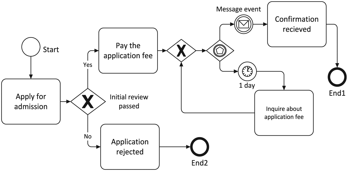
BPMN model of Example 1.
Analysis for Example 1 using GPenSIM
GPenSIM, a tool integrated with MATLAB environment, is used for the analysis of Petri net models. Figure 13 illustrates the simulation result of a student who is applying to the university for an admission. The x-axis shows the firing times, whereas y-axis depicts the number of tokens in places. Initially, the tokens are set to be 10 in initial place

Simulation result of Example 1 in GPenSIM.
Analysis under TINA tool
The transformed Petri net model of Example 1 (applying for an admission) is shown in Figure 14 and the verification results are illustrated in Table 2. The result displays that the transformed Petri net model of Example 1 is neither live nor safe. In fact, it is an ordinary Petri net which consists of one place invariant and no siphons in it. Initially, tokens are set to be 10 in place

Transformed Petri net model of Example 1.
Analysis of Example 1 in TINA.

TINA: Timed Petri Net Analyzer.
Example 2
The BPMN model of a patient having an accident being admitted to the hospital is created in Signavio Process Editor. As shown in Figure 15, the patient is brought to outpatient department (OPD) and a token is assigned to the patient. The patient is then shifted to emergency because of his critical condition. After that, he is referred to surgical specialist and at the same time his tests are conducted, and the lab reports are transferred to medical specialist

BPMN model of Example 2.
Analysis for Example 2 using GPenSIM
The simulation result of an accidental patient after transforming it to Petri nets using our developed software package is depicted in Figure 16. Initial tokens are set to be 10 in place p0. The probability is set with the inclusive gateway and the initial tokens will divide accordingly, whereas there is no need to involve probability with parallel gateway as all tasks need to be performed in parallel. The probability of the tasks

Simulation result of Example 2 in GPenSIM.
Analysis under TINA tool
The BPMN model depicted in Figure 15 is transformed manually into Petri net using mapping figures depicted in section “Preliminary background.” The transformed Petri net model of a BPMN model shown in Figure 15 is depicted in Figure 17 and verification results of the transformed Petri net model are illustrated in Table 3 which shows that the transformed net is pure and is ordinary, which neither has any place or transition invariants nor any siphon. Furthermore, it is bounded and a free-choice Petri net. As TINA lacks addition of probability to the gateways, we can only add firing delays to the transitions in TINA. Tokens can be moved between the initial and final time of transition once the initial time of a transition is enabled.

Transformed Petri net model of Example 2.
Analysis of Example 2 in TINA.

TINA: Timed Petri Net Analyzer.
S-soundness
Soundness is a notion of correctness of WF nets. The need of S-soundness arises for the exclusive and event-based gateways. It states that the number of tokens in source place is equal to the sum of tokens in the sink places.
Definition 6. (S-WF net)
A Petri net
There is a source place
If a transition
Definition 7. (S-soundness)
A S-WF net
The option to complete (for every case, it is always possible to reach the state marked as
Proper completion (for every case, if
No dead transition;
The number of tokens in the source place should be equal to the sum of tokens in the sink places.
Formally
The soundness property relates to the dynamic behavior of WF nets. As from Definition 7, the first and the foremost requirement is that it should always be possible to reach final state, that is, tokens in the sink places, starting from the initial state. From Figure 18, it is clear that there is a single token in place

Example of S-soundness.
Remaining token problem
A process model is accomplished when at least one of the end tasks has been performed at least once and for that process instance there is no other enabled task. In terms of Petri nets, for a single process, if there is any token in a sink place, the rest of places should be empty. If there is still a token remaining in rest of the places except the source and sink ones, the process may not be completed properly. In Figure 19, if Task 3 is enabled and fired, the process will be completed but a token will be left in between Task 1 and Parallel join at place p4. In this scenario, the process needs to be corrected in order to properly remove this remaining token. The analysis results in Figure 20 depict that the number of tokens in the sink and source places is not equal, which shows a deadlock in the system. Now, if the token is not terminated, there might be two cases, that is, either it will be a deadlock or a livelock. For the manual method, the places will be back-tracked to determine the token location in the Petri net model, whereas in the automatic method, GPenSIM itself will determine the location of the unterminated token in the model, which indicates the defected part of the model.

Petri net model with improper completion.

Analysis of Petri net model with improper completion in GPenSIM.
Comparison of number of elements in both standards
The simulation experiments are carried out with the help of using randomly generated BPMN processes. In Table 4, based on the simulation, we present the comparison of the number of elements in these two models. Using a Petri net model, we can perform dynamic analysis in contrast to static analysis using BPMN. The simulation time using GPenSIM in MATLAB is shown in Table 4.
Comparison of number of elements in BPMN and petri net standards.

BPMN: Business Process Model and Notation.
The tasks, events, and gateways of the BPMN model in Table 5 are taken from the work by Dijkman et al. 26 and the transformation time is compared with our proposed approach which includes transformation and analysis time. It can be seen that there is a significant reduction in time using the proposed approach compared with the work by Dijkman et al. 26
Comparison of transformation time with the work by Dijkman et al. 26

BPMN: Business Process Model and Notation.
Conclusion and future work
The BPMN standard lacks formal semantics, which limits its applications since one cannot examine the correctness of BPMN models from the perspective of syntax. We choose Petri nets as a dynamic model for verification due to their simulation capabilities, including mathematical functions and some other toolboxes in MATLAB. The contribution of this article is the extension of subset of BPMN elements that are transformed onto Petri nets. Furthermore, the addition of time with the tasks and the probability with gateways add additional features to business process modeling. Using the proposed mapping rules, a software package is developed that transforms BPMN elements onto Petri nets. Simulation results show that using this technique, the transformation time is subsequently reduced. The manual method further helps us view Petri net elements graphically, as well, and provides some other analysis properties such as safeness which GPenSIM lacks. Our future research is to make transformation of all BPMN constructs on the basis of the formalism proposed by Kheldoun et al. 69 and extended with time and probability. Moreover, we will study the deadlock problem 90 in a business process model and use this model to the wireless sensor networks.91,92
Footnotes
Handling Editor: Tatsushi Nishi
Declaration of conflicting interests
The author(s) declared no potential conflicts of interest with respect to the research, authorship, and/or publication of this article.
Funding
The author(s) disclosed receipt of the following financial support for the research, authorship, and/or publication of this article: This work is supported by the National Natural Science Foundation of China, under grant no. 61873342, and the Science and Technology Development Fund, MSAR, under grant no. 122/2017/A3.