
Abstract
In order to improve the impact ejection performance of the flexible airbag and to reveal the airbag inflating mechanism, a simulation model was built and verified by carrying out the flexible airbag impact ejection test. Based on this model, the influence of mass flow, compression displacement, and airbag thickness on flexible airbag ejection impact performance were studied. The results show that the ejection velocity of the flexible airbag increases as mass flow increases, but the excessive air mass flow does not improve the impact ejection performance of the airbag. The simulation results also demonstrate that the flexible airbag will oscillate reciprocally after it has no more contact with the moving rigid body and every node in the flexible airbag model has the same oscillating displacement. The analysis of compression displacement shows that it has a significant effect on the improvement of ejection performance. In conclusion, to improve the impact ejection performance of flexible airbag, the mass flow and compression displacement should be changed in a certain scope, which can provide reference for the topological structure design of the flexible airbag.
Introduction
With the rapid development of high-speed railway and the increase of vehicle running speed, more and more attention has been paid to the passive safety of trains. Flexible airbag can service as a new impact ejection power source which provides an approach for the crashworthiness test of the vehicle body. It can perform blast ejection1,2 with compressed gas in a limited space.3,4 Therefore, it is important to explore the key factors which can influence the impact ejection performance of the flexible airbag.
In the 1950s, the airbag was used as a safety conversion device for automobiles and the first automotive airbag patent was granted to JW Hetrick. 5 Nowadays, the airbag products are widely used in the aerospace and military fields. From the aircraft crash landing buffer to the recovery of the spacecraft return capsule,6–9 from air combat readiness to multistage rockets pressure separation,10,11 the airbag has undergone a rapid developing period. Deng and Pei 12 used the control volume (CV) method to study the inflating process of the folded airbag of the “Pathfinder” Mars system. In the fields of heavy equipment airdrops, hole area, height, and volume ratio of the primary and secondary airbags were optimized to improve the cushioning performance by Niu et al. 13 Cai et al. analyzed the airbag design parameters and the landing attitude for the impact of the buffer effect. The hybrid airbag scheme proposed can provide a reliable soft support in the later stage of soft landing process and reduce the risk of suffering the rigid impact. 14 Lu et al. conducted the curtain airbag finite element modeling and built the side collision system. They realized the auto-meshing of the folded curtain airbag by following the topology mapping theory. 15 Zhang et al. 16 simulated the dynamics of planetary soft landing airbag cushioning system and validated the capabilities of the self-standing and separation airbag’s buffering and landing system. Ning et al. 17 studied the airbag rupture jet flow field and gasbag rupture jet with different ruptured positions and obtained the variation of the internal pressure of gasbag and its influence on projectile motion. JY Li et al. 18 and HJ Hong et al. 19 proposed a modification for cushioning airbags and an evaluation method for airbag system. In recent years, Schenck from Germany, HYGE, MTS, IST Schenck from United States, Mitsubishi Heavy industries from Japan, and so on have successively developed the collision test acceleration methods such as using hydraulic drive and cylinder drive. 20 Although these driving methods are powerful and applicable, the disadvantages are obvious. For example, the feedback cycle is long, the sound explosion is more serious and the speed control is inaccurate. As a new type of impact ejection device, the flexible airbag can overcome above shortcomings, so it is important to carry out research on the impact performance of flexible airbag. Liu et al. 21 investigated the ejection process and the behavioral changes of compressed air based on multi-section airbags. However, no more research has been reported related to the impact performance of flexible airbag.
Due to the specialty of the flexible airbag structure and the nonlinearity of the elastic characteristics, the traditional theoretical calculation method of elastic characteristics of the airbag is relatively complicated. Most of the research is carried out through experiments, which bring difficulties in the design and optimization of the airbag. This limits the application of the excellent performance of the flexible airbag to some extent.
In this work, the nonlinear finite element method was used to establish the flexible airbag finite element model based on LS-DYNA and LS-PREPOST software. The impact ejection performance of the flexible airbag was investigated to determine the key factors, which affect the impact ejection and the movement behavior characteristics in the impact process.
Flexible airbag model
Flexible airbag ejection model
As shown in Figure 1, the flexible airbag has a plurality of capsule units (N1, N2, N3), which are connected with each other to form a relatively closed airbag chamber and then form a flexible airbag ejection system. The unit (N1) comprises an air inlet hole and is connected with the fixed wall. The unit (N3) is freely connected with the moving body. High-pressure air flow is filled into the flexible airbag and pushes the moving body to accelerated ejection in the X direction.
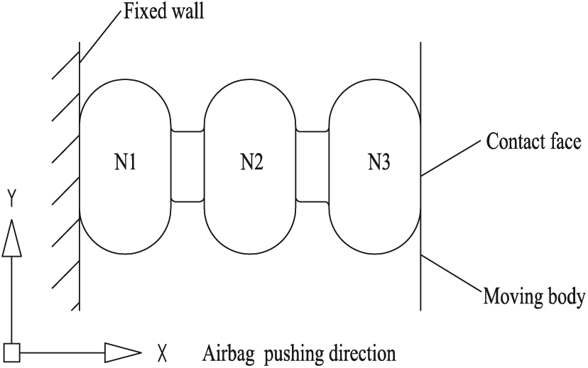
Flexible airbag ejection system model.
Mathematical model
The airbag model is developed using CV method. 22 As shown in Figure 2, the air cavity formed by unfolding the flexible airbag is divided into a number of finite volumes, such as (P1(t), P2(t)),…, P6(t)) by a virtual diaphragm. The air flow is filled from a finite volume N to its adjacent finite volume H and is controlled by the area of the virtual diaphragm AHN.

Airbag virtual discrete structure model.
Suppose the air flow in the airbag is one-dimensional quasi-static flow, when the Mach number Ma < 1, the gas mass flow equation can be written as

where mHN is the gas quality, P0 is the initial pressure, PU is the inlet pressure, Pd is the outlet pressure, γ is the specific heat capacity, G is the gas constant, T is the gas temperature, and Km is the balloon opening coefficient.
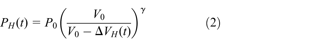
According to equation (1), the gas mass flow Qm of the adjacent finite volume at different moments can be calculated. Set the change of the total volume of the finite volume to be ΔVH(t), then its pressure can be described with
The increased volume of the air chamber for each controlled volume depends on the net influent gas rate and the dynamic balance between gas and diaphragm structure. Assuming at the moment of t – Δt, all the variables are known, then the approximation E(t) of the energy in each controlled volume can be written as

where cp is the specific heat at atmospheric pressure, Δt is the time interval, Tin is the temperature of the charged gas, and

where V(t – Δt) is the volume of the cavity at time (t – Δt).
According to the ideal gas law, the pressure in the cavity can be written as

In equation (5), k is the ratio of heat at constant pressure to volume. At the moment of t, the motion equation of the inflatable structure is

where [M], [C], [K] are the overall mass matrix, the damping matrix, and the stiffness matrix calculated, respectively. {R
ext
} is the external load vector including the pressure.
Above mathematical model and relevant equations provide necessary theoretical support for finite element modeling process. They are utilized when applying the *AIRBAG _ SIMPLE _ AIRBAG _ MODEL in DYNA, and some of the parameters are shown in section “Process of ejection in finite element simulation.”
Process of flexible airbag ejection
Physical process of ejection
The process of flexible airbag ejection can be divided into three steps: inflation, compression, and ejection. The inflation process uses constant velocity mass flow. The compression process can be achieved by constraining the displacement, while the ejection process can be finished by releasing the constraints within a certain period of time. As shown in Figure 3, the left end of the airbag is constrained by a fixed wall, and the right end is moving body with a concentrated mass, for which all the translational and the rotational freedom degrees except in ejection direction X are constrained. In Figure 3, A1 and B1 show the same initial free-inflating state of airbag. A2 and B2 are two different types of airbag compressed states. A3 and B3 reflect the completed state when the ejection is finished. All degrees of freedom of the moving body in A2 are constrained, while in B2 all degrees of freedom are constrained after the moving body is compressed a certain displacement in the X direction. Once the airbag is inflated for 0.02 s, the constraint in the X direction on the moving body will be released so that it can be ejected.
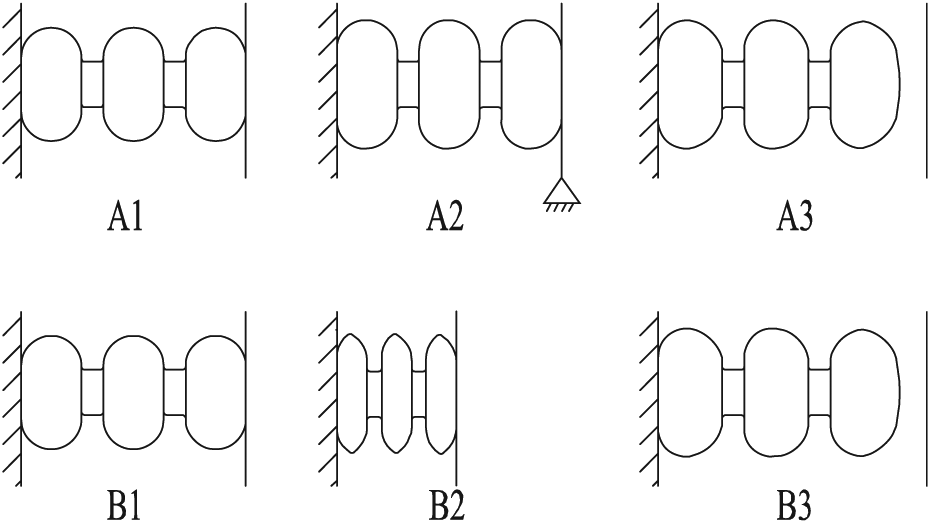
Flexible airbag three ejection process.
Process of ejection in finite element simulation
A flexible airbag ejection finite element model is established using shell element. The fixed wall and the moving body are simplified as rigid plate with the dimensions of 240 × 240 × 4 × mm, respectively. A concentrated mass is added to the moving body, and the total mass of the moving body is 100 kg. The flexible airbag is simplified with the dimensions of ø220 × 480 × 14 mm (the distance between the capsules unit is 24 mm). The boundary conditions, material properties, and airbag inflation model are set respectively and the simulation model is calculated in the DYNA solver. The *MAT_FARBIC element is selected to simulate the airbag with the element size of 3 mm, while the *MAT_RIGID element is chosen for dispersing the moving body and the fixed wall with the element size of 10 mm. The basic material parameters are listed in Table 1.
Fundamental parameters of flexible airbag ejection model.

Through the comparative analysis of the calculation results of the flexible airbag model with different size meshes and considering the calculation accuracy and time cost, the element size of 3 mm can meet the study requirement to the maximum extent. In the contact setting, a single surface contact is applied for the flexible airbag itself, while the surface-to-surface contact is used both between the airbag and the moving body, and between the airbag and the fixed wall.
Since the outlet of the air compressor is connected to the flow control valve which can adjust and determine the amount of air filled into the airbag, a constant mass flow can be ensured during the simulating process. Figure 4 illustrates an example of the ejection process using finite element model. The airbag is inflated with gas at a constant mass flow of 0.6 kg/s. After 0.02 s, the constraints of the moving body are released and it is ejected almost simultaneously.
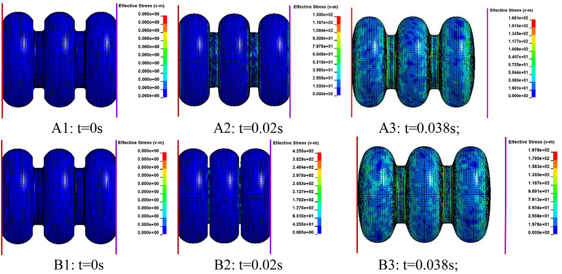
The form of flexible airbag pressured at all times (MPa). A1: t = 0 s, A2: t = 0.02 s, A3: t = 0.038 s, B1: t = 0 s, B2: t = 0.02 s, B3: t = 0.038 s.
The *AIRBAG_SIMPLE_AIRBAG_MODEL model was utilized to study the ejection and impact properties. Some of the mathematical model parameters introduced in section “Mathematical model” are listed in Table 2, which are used as input of airbag model in LS-DYNA to simulate the process of airbag inflation.
Model parameters in *AIRBAG_SIMPLE_AIRBAG_MODEL.

In Table 2, V0 is the initial filled volume; CV is the heat capacity at constant volume. CP is the heat capacity at constant pressure; T is the temperature of input gas; Pd is the ambient pressure; ρ is the ambient density. The inflow mass flow (Qm) is given by the load curve ID, LCID.
The gamma law equation of state (EOS) is adopted to determine the pressure in the airbag

where P is the pressure,

Model verification
Flexible airbag ejection test system and device
The flexible airbag ejector collision system as shown in Figure 5 consists of an air compressor, a dehumidifier, a cylinder body, a flexible airbag, a collision vehicle body, an ejection controller, and a rigid wall. One end of the flexible airbag is connected with the cylinder body while the other closed end is in contact with the collision vehicle body.

Flexible airbag ejection collision system.
First of all, the flexible airbag is restricted by the ejection controller, and then the air compressor starts to inflate the cylinder body with a certain mass flow. After specific time, the ejection controller is released. Under the effect of the pressed air, the flexible airbag pushes the collision vehicle body and accelerates the ejection. Finally, the flexible airbag is detached from the collision body.
According to the design of the flexible airbag ejection collision system, the ejection collision test device is assembled as shown in Figure 6. The mass of the collision vehicle body is 100 kg. The maximum ejection velocity of the flexible airbag under different mass flows is obtained through the speed sensor.

Flexible airbag ejection test device: (a) Coordinate definition of test device; (b) flexible airbag in compressed state; (c) flexible airbag after pushing out the vehicle body; and (d) speed detector.
The flexible airbag pushes the collision vehicle body to move along the X direction as it is shown in Figure 6(a). In Figure 6(b), the flexible airbag is in compressed state while in Figure 6(c) collision vehicle body is just pushed out by the flexible airbag. The speed detector is mounted on the device as shown in Figure 6(d). It consists of two photoelectric sensors and a single-chip microcomputer. The two sensors are separated by a certain distance. When the front end of the vehicle body passes the first sensor, the timing starts. Then, when the second sensor is triggered, the timing ends. The internal program of the single-chip microcomputer then calculates and displays the speed of the vehicle body, and the accuracy is 0.01 km/h.
The geometry and dimensions of the flexible airbag used in the ejection collision test are shown in Figure 7. The wall thickness of the airbag is 14 mm, and the material is composed of nylon fabric.
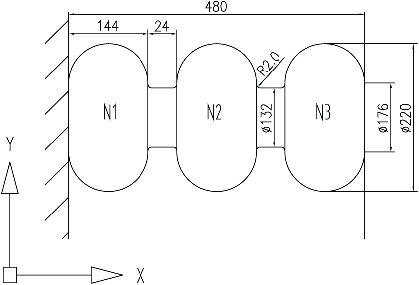
The geometric parameters of the flexible airbag.
Experimental test and simulation analysis
To verify the applicability of the simulation model described in section “Process of flexible airbag ejection,” experimental test data obtained using the test device and the finite element simulation data were compared. As the ejection speed is the most important factor to measure the ejection performance of the flexible airbag, and it is also the key parameter to study the crashworthiness of the vehicle body, the comparative analysis of the ejection velocity between the experimental test results and the simulation results is very convincing to illustrate whether the finite element model is applicable.
A mass flow of 0.6 kg/s was applied to inflate the cylinder body by the air compressor. At the same time, the flexible airbag was compressed 20, 30, 40, 50, and 60 mm, respectively. The ejection velocities are obtained by experiments and numerical simulations, respectively. The results are shown in Figure 8.

Test and simulation ejection velocity contrast.
Apparently the experimental results and the simulation analysis results are close to each other. Therefore, the correctness of the simulation model can be verified.
Results and discussion
Influence of mass flow on impact performance
The difference in mass flow can affect the impact performance of the flexible airbag. In order to exclude the interference of the external factors while introducing the mass flow, the constrained compression of the moving body (keep the position of the moving body to be fixed when the airbag is inflated) is applied. The mass flows are selected to be 0.2, 0.3, 0.4, 0.5, and 0.6 kg/s. The constraint of the moving body is released at the moment of 0.02 s, and under the action of internal pressure, the flexible airbag rapidly promotes the moving body to accelerated ejection. The ejection speed of the flexible airbag is obtained by measuring the overall speed of the moving body which is a rigid element. Figures 9 and 10 show the changes of the ejection velocity and of the ejection impact force with different mass flows.

Ejection velocity of moving body with different mass flows.

Ejection impact force of moving body with different mass flows.
The results show with the increase of the mass flow, both the ejection velocity and the ejection impact force turn higher. However, the increasing amplification of the ejection velocity does not show linear relation with the mass flow. This may be because when the mass flow increases, the contact time between the airbag and the moving body will decrease accordingly.
The ejection acceleration of the moving body is an important index to measure the impact performance of the flexible airbag. The larger the acceleration is, the larger the impact force of the flexible airbag acts on the moving body, and also the larger the ejection speed can be obtained. Figure 11 shows that the impact acceleration of the flexible airbag on the moving body in X direction.

Impact acceleration of a flexible airbag on a moving body.
As can be seen from Figure 11, the acceleration of the moving body increases at the beginning and maintains same rate for a period, at the end the acceleration drops to zero. The flexible airbag rapidly generates acceleration on the moving body after the constraint is released. At this moment, the size of contact area between the flexible airbag end surface and the moving body changes very little. Therefore, the acceleration is almost a constant at this stage. As the velocity of the moving body increases, the contact area with the end portion of the flexible airbag decreases, so the acceleration starts to decrease. At the moment when the acceleration reduces to 0, the airbag is out of contact with the moving body. The acceleration peak of the moving body increases with the increase of the mass flow, but the acceleration time range is decreased. Meanwhile, the result shows that the smaller the mass flow is, the wider the time ranges for accelerating the moving body are. This is also the main reason why the velocity of the moving body does not change linearly with the increase of the mass flow.
On the other hand, the change of the internal energy can also reflect the ejection performance of the flexible airbag. The change rule of the internal energy was studied by setting different mass flows, as shown in Figure 12.
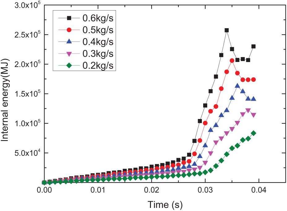
Airbag internal energy changes with the mass flow.
The internal energy of the flexible airbag increases with the increase of the mass flow. After 0.027 s, the internal energy starts to surge suddenly. When the first peak is reached, the internal energy begins to fluctuate. This is also the reason causing the oscillatory expansion and contraction after the airbag is disengaged from the moving body.
In order to study the motion law of different nodes on flexible airbags, five measurement points were chosen at different distances in the longitudinal direction of the airbag, as shown in Figure 13. The left end of the flexible airbag is fixed, and the right end is in free contact with the moving body. The mass flows are selected to be 0.6 kg/s, and the thickness of airbag is set as 14 mm. Figure 14 indicates the motion displacement changes of these points.

Airbag longitudinal measurement point distribution.

Longitudinal motion displacement of the airbag.
It can be seen that the motion displacement of the point near the contact end surface is greater than that of the point far away from the contact end surface. Thus, it can be concluded that the free end of the airbag first produces large deformation while the fixed end produces relatively smaller deformation; as the ejection time increases, the flexible bag starts to oscillate. In particular, when the airbag and the moving body are out of contact, the airbag has a significant oscillatory. The relative displacement of each point in the flexible airbag is the same, and there is no difference in the amount of displacement due to the distribution of points. Figure 15 shows the relations of airbag pressure and its volume over time with a mass flow of 0.6 kg/s.

The pressure and volume changes over time.
It can be seen that the trend of volume change of the flexible airbag before releasing the constraint to the moving body is not obvious, and the pressure increased approximately linearly, and the pressure increases linearly. After 0.02 s when the constraint is released, the volume of the flexible airbag increases rapidly. At 0.015 s, the volume of flexible airbag increases from 3.88 × 10⁶ to 4.33 × 106 mm3, while the pressure growth rate decreases significantly over time and then returns back to previous rate. After 0.035 s, the flexible airbag was separated from the moving body and begun to oscillate, so the volume of the flexible airbag begin to fluctuate.
The pressure and volume change inside the flexible airbag with different mass flows is one of the key factors to study the ejection properties of the airbag. Figure 16 shows the relationship between volume and pressure of the flexible airbag with different mass flows.

Volume of flexible airbag varies with pressure at different mass flows.
It can be seen that from the initial volume of 3.76 × 10⁶ to 3.88 × 106 mm3, the volume and pressure of the flexible airbag are the same with one another under different mass flows. When the pressure is greater than 0.6 MPa, it increases with the increase of mass flow. The volume of the flexible airbag rapidly expands when the pressure increases from 0.6 to 2 MPa. Then, the flexible airbag with different mass flows oscillates in a reciprocating manner. The larger the mass flow is, the greater the oscillation is.
Influence of compression displacement on impact performance
The compression displacement refers to the movement of the moving body by constraining the freedom of translation of itself so that the moving body compresses the flexible airbag to a certain distance within a specified time. The flexible airbag was compressed a distance of 20, 30, 40, 50, and 60 mm at 0.02 s, respectively. At this time, the compression displacement of the moving body is released so that it will be ejected only at the direction X.
The compressed distance on the flexible airbag plays an important role on the ejecting velocity of the moving body. With the increase of the compression displacement, the ejection distance and acceleration time of the flexible airbag to the moving body can be significantly improved. At the same acceleration rate, the longer the action time is, the larger the displacement will be. The ejection velocity increases as the compression displacement increases. Figure 17 shows the change relationship between ejection velocity and compression distance.

Ejection velocity of flexible airbag to moving body with different compression displacements.
When the compression distance is 50 mm, the compression displacement and the ejection velocity increase at the same rate. The larger the compression displacement is, the faster the ejection velocity of flexible airbag will be. However, the upward trend will slow down when the compression displacement is greater than 50 mm. Therefore, the compression displacement of the flexible airbag is not unlimited. Since the length of the airbag itself may have a certain influence on the compression displacement, the ejection velocity does not always increase linearly with the increase of the compression displacement. Figure 18 shows the acceleration curves under different compression displacements.

Acceleration curves under different compression displacements.
It can be seen from the above picture information that as the compression displacement increases, the acceleration of the moving body increases rapidly. The acceleration rate of moving body when the compression displacement is less than 40 mm is far less than the acceleration rate when the compression displacement is more than 40 mm. It will increase steeply when the compression displacement is 50 mm. Under different compression displacements, the acceleration time is almost equal, and the larger the compression displacement is, the shorter the peak acceleration time. This is why the ejection velocity does not increase at the same rate when the compression displacement is larger than 50 mm.
The pressure and volume changes are the key factors in studying the ejection properties of the flexible airbag. Figure 19 shows the relationship between the volume and its internal pressure under different compression displacements.

Volume–pressure relationship of flexible airbag under different compression displacements.
The initial volume of the flexible airbag is 3.76 × 106 mm3. Before the constraint is released, the pressure increases as the volume decreases. When the constraint is released, the pressure starts to decrease as the volume of flexible airbag increases. Finally, the volume of flexible airbag starts oscillating and contracting. The flexible airbag has gone through three phases (from compression to volume expansion and then volume oscillatory contraction), and the pressure has undergone a process of increasing, decreasing, and finally increasing.
Influence of flexible airbag thickness on impact performance
The effect of flexible airbags thickness on the ejection performance was carried out with a compression displacement of 50 mm. The thickness of airbag is set as 6, 8, 10, 12, and 14 mm, respectively, while the mass flow is set as 0.6 kg/s in all cases. Simulation analysis was performed on different thicknesses of flexible airbags. Figure 20 shows the ejection velocity of the flexible airbag to the moving body at different thicknesses.

Ejection velocities of flexible airbags with different thicknesses.
It is shown that although the thickness is different, the ejection velocity of the flexible airbag does not change significantly. At the beginning of ejection, the flexible airbag starts to push the moving body to accelerate the ejection. During the time from 0.02 to 0.035 s, the airbag starts to disengage from the moving body. There has trivial difference in the airbag ejection velocity for different thicknesses.
This case is analyzed by studying the ejection acceleration of the flexible airbag to the moving body. Figure 21 shows the ejection acceleration of the moving body at different thicknesses.

Ejection acceleration of flexible airbag at different thicknesses.
It is noted that the acceleration of the flexible airbag can be divided into two stages. The acceleration with different thicknesses reaches the same value at 0.027 s. Before this moment, the ejection acceleration increases slightly with the increase of the thickness. Then the acceleration decreases with the increase of the thickness. No obvious change in the impact performance of the airbag is observed, which indicates that the thickness of the airbag has little influence on the ejection velocity. Figure 22 shows the relationship between the internal pressure and the volume of the flexible airbag with different thicknesses.

The relationship between volume and pressure of the flexible airbag with different thicknesses.
The relation between the volume and the pressure shows the same trend with different thicknesses during ejection. After the flexible airbag is separated from the moving body, the smaller of the thickness is, the larger the volume is, which is consistent with the actual situation.
Conclusion
By utilizing a self-developed simulation model of flexible airbag impact ejection system, the effect of mass flow, compression displacement, and airbag thickness on airbag ejection is investigated, and the validity of the simulation model is proved by experimental test.
By changing the mass flow and compression displacement, the ejection impact performance of flexible airbags can be further improved. The change in the thickness of the flexible airbag has no effect on the improvement of the impact performance. The flexible airbag will oscillate reciprocally once it is separated from the moving rigid body, and each node chosen in the flexible airbag model has the same oscillating displacement.
Present work is the first step to improve the impact ejection performance of the flexible airbag and to study the airbag inflating mechanism. Based on the model, the topological structure of the flexible airbag is still to be studied based on present model in the future.
Footnotes
Handling Editor: Jianjun Zhang
Declaration of conflicting interests
The author(s) declared no potential conflicts of interest with respect to the research, authorship, and/or publication of this article.
Funding
The author(s) disclosed receipt of the following financial support for the research, authorship, and/or publication of this article: The authors gratefully acknowledge the support of the National Key Research and Development Program of China (2016YFB1200404), the National Natural Science Foundation of China (51675446), and the Independent Subject of State Key Laboratory of Traction Power (2017TPL_Z01).