
Abstract
Recently, the demand for designing mechanism-embedded artifacts has increased in personal digital fabrication. However, it is difficult for nonexperts without engineering knowledge to design and build a prototype with a kinetic mechanism. We present M.Sketch, a prototyping tool that helps nonexperts to design and build linkage-based kinetic mechanisms. It enables the user to easily configure the linkage-based mechanism with a simple interface applying a geometry drawing metaphor. The tool features computational support, including interactive visualization, top-down optimization, and connection to digital fabrication, to obtain and build the desired movement. In order to support science–art integrated science, technology, engineering, the arts, and mathematics (STEAM) education related to digital fabrication of interactive artifacts, we deployed M.Sketch in design workshops and student contests of walking robot design. The participants in the contests were able to successfully design and build walking robots with the Theo-Jansen mechanism using various support features of M.Sketch. Based on the development and deployment in science, technology, engineering, the arts, and mathematics educational domains, we figured out several implications, and further improvement points of prototyping tools supporting nonexperts in designing mechanism-embedded interactive artifacts.
Keywords
Introduction
Personal digital fabrication has become popular as fabrication methods and equipment, such as three-dimensional (3D) printers, laser cutters, and computer numeric control (CNC) machines, have become inexpensive and easily accessible. 1 At the early stage of maker culture with emerging digital fabrication technology, most makers and end users attempted to design and build simple everyday products as an extension of do-it-yourself (DIY) culture. Since the performance of digital fabrication machines has been improved, makers have been able to build complicated and sophisticated artifacts that are systemically assembled with smaller parts.2–5 Recently, the assembled artifacts have been integrated with electronic actuators and can be controlled to interactively move through a physical computing method. The kinetic mechanism has been one of the popular methods to build a wide range of movable and transformable artifacts with tangible expressions, including automata, interactive robots, and DIY smart products.6–8
The process of building and testing kinetic movement allows people to learn the related knowledge of engineering and technology. Many science–art integrated educational programs, called STEAM (science, technology, engineering, the arts, and mathematics) education, have attempted to train students in integrated thinking and abilities through building kinetic artifacts, such as interactive robots and automata.9,10 However, building the artifacts having kinetic movement involves a complicated design process requiring advanced knowledge of engineering. The resulting movement of kinetic mechanisms, such as linkage-based mechanisms, is unpredictable without an additional analysis process. 11 Engineering experts are accustomed to the design process with their knowledge and experiences, whereas it is difficult for nonexperts, including makers, designers, and students, to obtain the desired movements.
Several design tools, such as Linkage 12 and SAM, 13 have supported the design of linkage-based mechanisms. These software tools allow people to configure and simulate the mechanisms to achieve the desired movement through an iterative process. However, they focus on the calculation and analysis of mechanical configurations and lack support for nonexperts to build physical prototypes with digital fabrications. Meanwhile, professional modeling software including Solidworks 14 and CATIA 15 enable experts to design 3D parts. Simple and light modeling tools such as Tinkercad 16 have also been provided for beginners to deal with 3D models for digital fabrication. However, these modeling-based tools require significant time and effort to learn sophisticated techniques to deal with complicated moving mechanisms. There is still insufficient support for nonexperts to efficiently design and fabricate mechanism-embedded artifacts. 17
In this article, we present M.Sketch, a prototyping tool designed to support nonexperts in designing and building linkage-based kinetic mechanisms (Figure 1). M.Sketch features a simple and intuitive interface for nonexperts to easily learn and use with a metaphor of geometry drawing. It also embeds various computational support features for achieving the desired movement. The interactive visualization and optimization support nonexperts to design with trial-and-error and top-down approaches. Moreover, it provides fabrication support for the connection of a mechanism design for the digital fabrication phase. M.Sketch is a readily available Web-based application (http://msketch.kaist.ac.kr). This article illustrates the detailed features and design rationales of M.Sketch and reports the implications from its development and deployment. To support STEAM education, we deployed the tool in various domains, such as educational workshops and student contests for walking robot design. The deployment revealed that the tool allowed the users to achieve the desired movement of kinetic mechanisms. It also discussed issues of further computational support for nonexperts in digital fabrication of mechanism-embedded artifacts.

Snapshot of the M.Sketch interface: Illustrating mechanism sketch and path visualization of the Klann and Theo-Jansen mechanisms.
Related works
Algorithms for mechanism generation
It is challenging to design a kinetic mechanism in the early stage of prototyping due to the unpredictable aspects of the movement. Several computational algorithm approaches have attempted to support nonexperts to achieve kinetic movement from the initial idea. Coros et al. 18 presented a technique that automatically generates the linkage-based mechanism from the desired path. It creates gear-linkage assemblies to enable tangible expression of mechanical characters similar to the drawn input movement. Ceylan et al. 19 utilized a motion capture sequence as an input for generating mechanical human automata. ChaCra 20 enabled generation of the linkage-based mechanism by sketching the geometric parts and placing them in the extreme locations of movement. Zhu et al. 21 presented an algorithm to construct the mechanical automata from 3D-modeled characters and their movement. Thomaszewski et al. 11 presented a system that suggests several alternatives of a linkage-based mechanism to allow the user to interactively explore the various mechanisms during the design process. Previous works supported a rapid and effective mechanism design process by generating an appropriate result from the desired movement. However, these focused on the development and demonstration of associated approaches and algorithms to generate the mechanism in specific conditions and contexts. Our tool is differentiated in that it was implemented as practical software and an interface to support users to involve an integrated design process from conceptual design to digital fabrication in the linkage-based mechanism.
Computational design for digital fabrication
Several tools were presented to support the generation of model sources for digital fabrication with computation support such as simulation, optimization, and parametric design. CardBoardiZer 22 converts a 3D model into a two-dimensional (2D) crease-cut-slot pattern for fabricating artifacts by folding paper. It also automatically synthesizes hinges for moving parts according to the user’s input on virtual 3D models. Nakamura et al. 23 presented a system that simulates, optimizes, and fabricates free-formed bamboo-copters. FlatFitFab 24 enables the user to design a 2.5-dimensional (2.5D) structured artifact consisting of a planar section with various interlocking methods. The tool also supports a physical simulation of stress and stability for the designed model. Meanwhile, several studies investigated transformable properties of fabricated artifacts. Megaro et al. 25 presented a method that converts rigidly articulated mechanisms to 3D-printable compliant ones with flexible materials. It minimizes the motor torque and material failure by simulating and optimizing the flexible joints. Ion et al. 26 presented a tool for designing a meta-material mechanism that enables movement with a pattern of cell structures instead of a rigid joint. Several works applied the parametric design approach to explore and obtain various design alternatives of specific artifacts for digital fabrication. FoldMecha 27 generates paper-folding nets to build two types of kinetic paper automata. Pteromys 28 supports the parametric design of paper airplanes, and SketchChair 29 enables DIY chair design. While previous works focused on specific materials or structures, our tool was designed to support various digital fabrications of arbitrary configurations of linkage-based kinetic mechanisms.
Tangible aids for kinetic movement
In digital fabrication, an iterative process with trial-and-error is frequently used to derive better results. The trial-and-error method requires significant time for the whole process involving designing, building, and modifying the artifacts with kinetic movements. A ready-made tangible aid can be a solution to effectively conduct an iterative process with rapid building and testing. 30 Lego Technic, 31 Meccano, 32 and Science Box 33 are popular commercial modular kits that enable rapid prototyping of movable and transformable structures. Moreover, they have already been used in various creative education programs or design practices. Several tangible tools have been presented to support rapid materialization of kinetic movements. Topobo, 7 CUBEMENT, 34 and Kinematics 35 allow the user to create movements with block-typed tangible kits that can be easily assembled and actuated. LINKKI 36 is a tangible prototyping tool for building linkage-based kinetic mechanisms with modularized mechanical parts. These tangible aids can reduce the time and effort necessary in the early phase of mechanism design. However, it is difficult to derive a precise design result due to the low fidelity and resolution of predesigned hardware parts. Our tool supports hybrid fabrication integrating custom fabricated parts and an existing modular kit (Science Box) for effective building and testing processes.
Digital fabrication in education
Digital fabrication is one of the promising means for STEAM education. The integrated design process involving continuous ideation, fabrication, and reflection enables people to improve problem-solving abilities. 37 Digital fabrication involving tangible aspects has been widely used in various educational contexts. Digital design and fabrication have been used as sketching tools for architectural design 38 and product design 39 education. Blikstein 40 presented cases of digital fabrication that were applied to educational contexts beyond science and math: history and music. He also articulated that digital fabrication can be used for enhancing and augmenting existing practices and expertise that students already possess. Meanwhile, there have been several attempts to integrate digital fabrication into physical computing education. Building interactive artifacts with various materials and tools, such as LilyPad Arduino, 41 enables students to understand and utilize physical properties—aesthetics, representations, and materials—as well as logical thinking. 42 Compared to static models, movable and transformable artifacts involving robots require more advanced knowledge, experience, and computational support. Few effective and integrated methods and tools exist for nonexpert learners to design and build those complex artifacts. In this article, we report a case in the educational context in which our tool was used by nonexperts for robot design.
Design of M.Sketch
Purpose and considerations
M.Sketch was developed for the purpose of usage in the STEAM educational context. It was designed for nonexperts of mechanism design (e.g. students and makers) to easily design and build linkage-based kinetic mechanisms. A linkage-based mechanism is a fundamental configuration of movement in mechanics. It can provide sophisticated movement with simple connections of linkages and a single rotary actuator. This simple configuration has been applied for creative design education and makers’ activities such as creating automata, robots, and kinetic art sculptures. Our key consideration was to implement a simple and intuitive interface for nonexperts to deal with these linkage-based mechanisms to create various movements.
To support nonexperts’ mechanism design, we established several considerations before the development process. The first consideration was that the tool should provide a simple and intuitive interface to create linkage mechanisms as easily as common line-drawing tools. Also, it should effectively visualize the result for nonexperts to easily understand and check their expected movement. Another consideration was applying computational support to help nonexperts obtain the desired movement. The top-down design approach—a design process starting with formulating the overview of the expected result—was considered to be applied in M.Sketch. Beyond the design process, M.Sketch was also designed to support fabrication of tangible kinetic mechanisms. As illustrated in related works, various mechanism design and analysis tools already exist. However, there were few practical tools for fabricating kinetic mechanisms to build tangible prototypes of mechanism-embedded robots and products. In order to enable effective deployment in the educational domain, we considered implementing M.Sketch as light and highly accessible software.
M.Sketch was finally developed as a Web-based application and was deployed in various domains. It was introduced in various educational venues, such as lectures, workshops, and student contests. The first deployment was conducted in 2015. We frequently collect feedback from users and experts to improve the tool for better support of linkage mechanism design. Figure 2 shows the snapshots of major updates of M.Sketch.
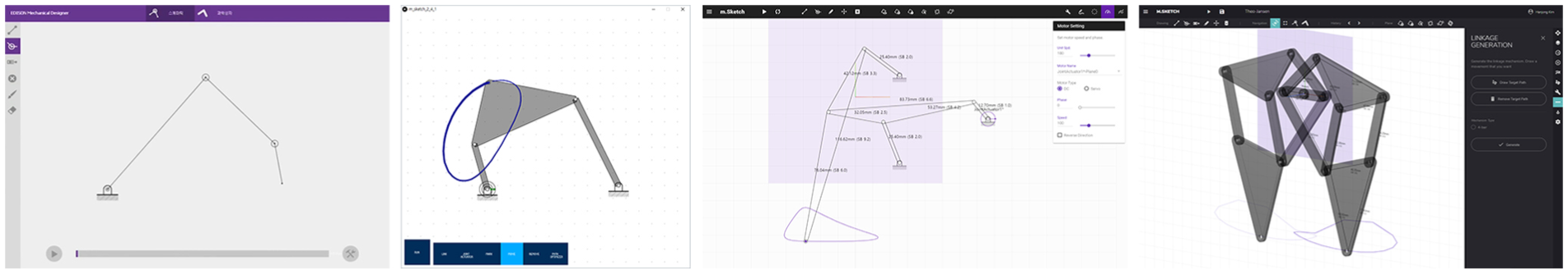
Snapshots of major updates: M.Sketch was developed from a conceptual prototype to the current Web-based version to improve the features of computational support and digital fabrication.
Mechanism Sketch
M.Sketch has an interface for the rapid design of linkage-based mechanisms. Users can simply draw and connect the links by clicking, dragging, and snapping, as in line-drawing. When a user drags on an empty space of the canvas, a new link that has an anchor at a starting point is generated. Then, the user can draw another link from the existing endpoint of a link to create a connected configuration (Figure 3(a)). A connection can also be enabled by dragging an existing point to a point of another link to snap and make a constraint of a joint. M.Sketch also supports drawing polygonal links. When the user drags any inner section of a link outward, a new point is extended to shape the polygonal link (Figure 3(b)). In order to create sophisticated movement, a link can be converted to a slider on which an inner sliding point moves along the link (Figure 3(c)). The sliding point can be connected to endpoints of other links.

Drawing a linkage-based mechanism using Mechanism sketch interface: (a) linear link, (b) polygonal link, and (c) slider.
After the early mechanism sketch of linkage configurations, the user can modify the linkage by moving the coordinates of joints by dragging. M.Sketch also enables specifying the coordinates of joints or the lengths of links by inputting numeric parameters. When the user completes the mechanism sketch, a motor can be assigned to a joint to actuate the drawn linkage configuration. M.Sketch then calculates the degree of freedom of each link and indicates whether it is well constrained or not with color feedback. Through these features, the user can simply draw arbitrary and complex linkage mechanisms using M.Sketch.
Movement visualization
Visualization of kinetic movement is essential for nonexperts to understand the design results. Several features were involved in M.Sketch to enable effective visualization of the movement. The first feature is providing animated kinetic movement by actuating assigned motors. A motor, which is assigned to an anchor point or a joint between two links, involves its type (direct current rotate or servo) and parameters (speed, direction, range, phase) reflected in the animated visualization (Figure 4(a)). The animation instantly visualizes the change of coordinates of each link according to the rotational values of motors.

Visualization of kinetic movement: (a) animated visualization and (b) preview of the movement path.
The second feature is visualizing an expected movement path. In order to focus on the displacement change of a certain endpoint of a link, a marking point can be assigned. M.Sketch instantly visualizes the expected trace of the marking point as a curved path according to the rotation range of the assigned motor. The path visualization can enable the user to check how a certain point moves at a single glance. For example, the path can be used to determine that a walking robot can step over obstacles. Moreover, the movement path is instantly reflected when the linkage configuration is changed (Figure 4(b)). When the user drags the joints for modification, the change of path can help him or her to obtain the desired result.
The third feature is a 2.5D visualization of entire mechanism system. A planar 2D configuration of the linkage-based mechanism can be a fundamental means to draw, assemble, and test in a simple way. However, it is difficult to envision the resulting kinetic artifact in terms of 3D physical aspects such as shape and dimension. M.Sketch enables users to deal with those aspects by extending 2D mechanism planes to be located in 3D space (Figure 5). Each mechanism plane can be duplicated by exporting and importing. The imported planes can be placed in the 3D space using translating, rotating, and flipping functions. Using this feature, the user can roughly configure the overall shape of an artifact such as a walking robot with multiple leg mechanisms. The comprehensive visualization of movement can be performed through 3D navigation when all planar mechanisms actuate together.

Comprehensive 2.5D visualization composed by 2D linkage planes located in 3D space.
Top-down design approach
M.Sketch was designed to involve a top-down design approach, which enables nonexpert users to easily obtain the desired movement through computational support. A linkage mechanism is a simple mechanism, but it is difficult for nonexperts to obtain their desired result. M.Sketch provides two features of the top-down approach based on the drawn path by nonexperts: generation and optimization of mechanisms that have a similar movement to the desired one.
The first computational support is that the system generates a mechanism based on the drawn desired movement path (Figure 6(a)). M.Sketch contains a mechanism dataset of basic four-bar and six-bar linkage configurations. When the user draws the desired path and runs the mechanism generation, M.Sketch compares the movement and finds the most similar configuration from the dataset. Another feature is optimizing the current configuration to fit into the desired path. When the user creates an arbitrary linkage mechanism and starts optimization with the drawn desired path, M.Sketch repeatedly changes each coordinate of joints to obtain a mechanism generating similar movements (Figure 6(b)). These features help nonexperts without knowledge of mechanism design to obtain a linkage-based mechanism with a similar movement to their desired result. The created mechanism with computational support can act as a starting point for the further design process.

Computational support for top-down design approaches based on the desired path input (red color): (a) generating a suggested mechanism and (b) optimizing the current mechanism.
Fabrication support
M.Sketch supports the fabrication process in the real world beyond the virtual design process. It aims to help nonexperts (e.g. designers and makers) build and test various artifact prototypes involving kinetic mechanical movements. In order to enable the connection with the fabrication process, M.Sketch can export 2D drawings of linkage configurations as a vector image format. An exported drawing in a PDF (Portable Document Format) file contains the assembled drawing, schematic drawing, and part drawing of each link (Figure 7(a)). The part drawing can be opened in existing vector drawing software (e.g. Adobe Illustrator or Corel Draw) and modified for available fabrication machines, such as laser-cutting and paper cutting machines. The user can assemble fabricated link parts referring to the assembled drawing (Figure 8).
Fabrication with M.Sketch: (a) exported drawing and (b) generated 3D parts.

Example of walking robot prototype designed and fabricated with M.Sketch.
M.Sketch also includes a feature for exporting 3D models of links and associated parts to support 3D-printing machines, which are commonly available (Figure 7(b)). The link parts designed with M.Sketch can be converted into extruded 3D form and be exported in OBJ format. We identified that assembling link parts in the real world brings about a 3D placement issue, such as interference caused by stacking order. Therefore, the extruded 3D links can be moved along the z-axis of the mechanism plane to check the 3D configuration. M.Sketch also provides generation of gears. The gear parts are generated according to the speed ratio of multiple assigned motors so that the mechanism can be actuated by a single input. The user can fabricate the 3D models of the generated link and gear parts, then assemble them to test a physical mechanism prototype.
In order to enable rapid fabrication for testing, M.Sketch supports hybrid fabrication with an existing commercial modular kit, Science Box. 33 The kit includes steel frames of various lengths with 0.5-inch spaced holes of 4 mm. It is also composed of various support parts such as shafts, bolts, nuts, and motors. To enable the support of the fabrication with Science Box, M.Sketch provides snap and length-conversion functions for the kit’s unit.
High accessibility
M.Sketch was developed as a Web-based application for use in public and educational domains. Users can access and use it directly with a Web browser that supports WebGL (e.g. Google Chrome and Mozilla Firefox) without any installation on their computers. The Web application also provides high device compatibility so that M.Sketch can be used with Android and iOS-based tablet PCs. M.Sketch provides a personal repository for each user. Users can save and open their projects via the server as well as upload and download the files.
Mechanism examples
Various types of linkage-based mechanisms can be generated using M.Sketch. We produced several example mechanisms and application cases using our tool to show its capacity and feasibility, as shown in Figure 9. We collected and generated examples of fundamental linkage-based mechanisms such as six-bar linkages involving Watt and Stephenson mechanisms from the area of mechanics. More sophisticated configurations including Theo-Jansen and Klann mechanisms could also be drawn using M.Sketch. We then accumulated several design cases related to kinetic mechanisms in the area of personal fabrication. Aside from some cases that apply additional non-linkage elements such as a cam, we were able to reconstruct the cases of automata, interactive toys, and kinetic arts using M.Sketch. We identified that most linkage-based kinetic mechanisms could be designed using M.Sketch, but specific configurations such as Stephenson II could not be processed due to the limitation of the applied computation algorithm. 43

Various example mechanisms reconstructed with M.Sketch: (a) fundamental mechanisms, including four-bar and six-bar linkages and (b) collected applications of arbitrary mechanisms.
Implementation
M.Sketch was developed as a Web-based application to provide high device compatibility. Its interface was developed with HTML, JavaScript, and CSS to run on standard Web browsers. Computations for linkage configurations, obtaining displacements according to their constraints, were implemented with JavaScript. The 3D visualization of the drawn linkages was implemented using Three.js WebGL API. M.Sketch runs on a Node.js-based server developed using the Express package and MongoDB. In order to manage the extended features, the interface components were separated into several panels in EJS format and collectively rendered via the Node.js view engine.
Displacement computation
M.Sketch computes the displacements of each link at a given moment when the linkage actuates. It analyzes the joint topology of the designed mechanism and obtains the positional states of links that are fully constrained. In order to interpret the joint positions of the designed mechanism configuration, we applied the symbolic reconstruction algorithm illustrated by Bächer et al.
43
Instant visualization of the movement path can be obtained through the calculation of the displacement of linkage for a single revolution of the assigned motors. The path involves 16 fragment points
Mechanism generation
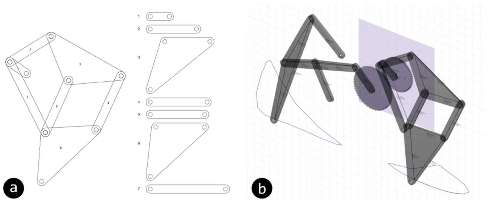
The mechanism generation based on the desired movement path was implemented, with an approach of finding the most similar mechanism. We applied the basic four-bar and six-bar linkages to compose our mechanism dataset because these simple configurations can generate various circular movements through the alternation of lengths and placements of link parts. In particular, the Watt I mechanism from the six-bar configuration has the potential to enable a wider range of dynamic movements.
44
We designated point

Linkage configurations for mechanism generation: (a) target points for four-bar and six-bar linkages and (b) example configurations generated in the dataset.
We adopted dynamic time warping (DTW)
45
to obtain the most similar mechanism to the input movement path from the dataset. M.Sketch obtains a target path from the user’s path drawing. The drawn path is reconstructed to the closed path by connecting the start and the end points. The closed path is then re-sampled and normalized to be the same as the dataset

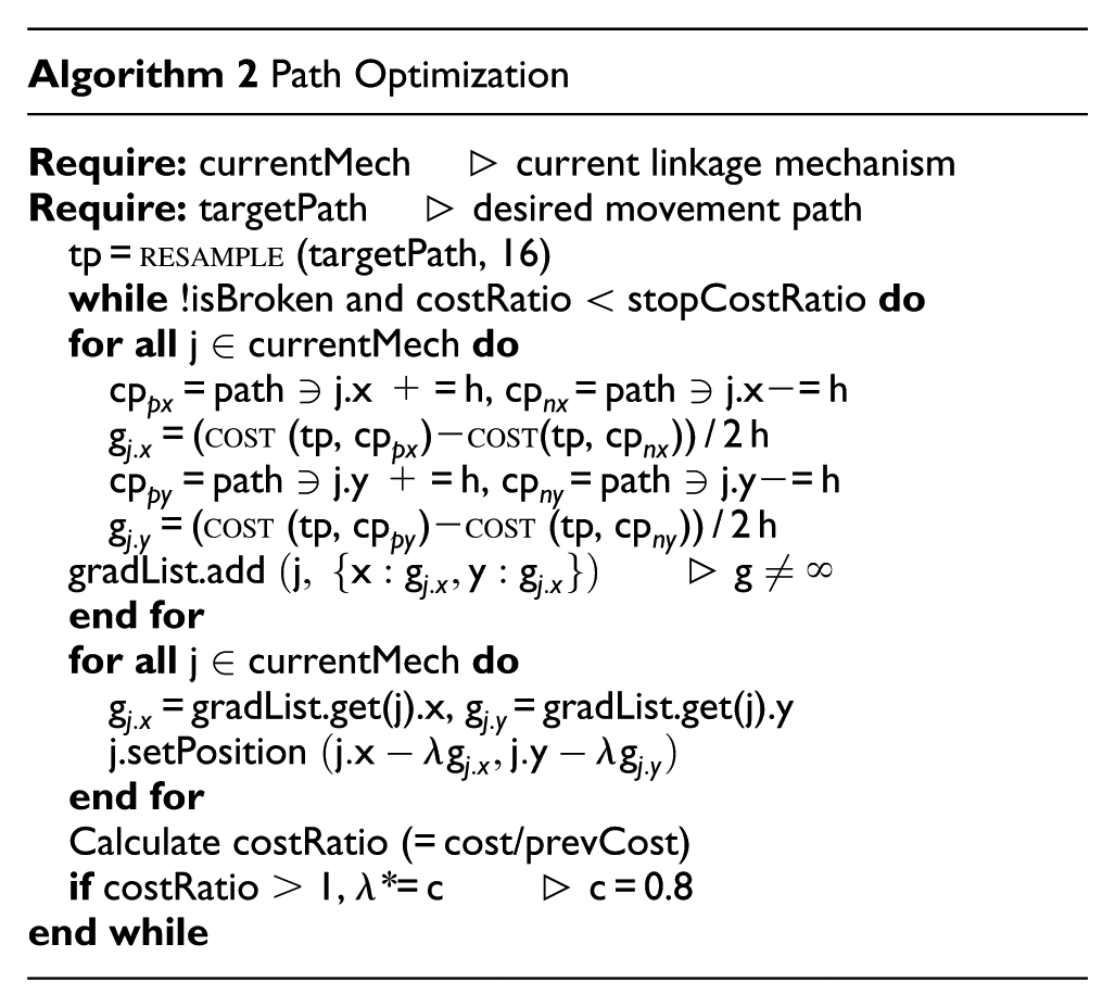
Path optimization
Optimizing the current linkage configuration fitting to the desired path is one of the top-down design features implemented in M.Sketch. It obtains a closed target path from the user’s path drawing in the same way as the mechanism generation. The closed path is then re-sampled at equal intervals by 16 points


In the equation above,
M.Sketch in STEAM education
We deployed M.Sketch and the associated contents into STEAM educational contexts. We focused on identifying how M.Sketch can be used as well as its usability issues and improvement points. The target contexts were a workshop course and a student contest related to makers’ activities, such as interactive product and robot design. We introduced M.Sketch in various workshop venues and deployed it via public domain for ready use. Besides, we made M.Sketch mandatory software for an annual student contest to design a walking robot. Throughout the 3 years of deployments to the contests, we have collected feedback from nonexpert users and experts in mechanical engineering domains, and then improved it continuously.
Mechanism design workshop
The first educational content related to M.Sketch was a 2-h workshop course on kinetic mechanism design. The earlier part of the workshop involved a short lecture about linkage-based mechanism design and a basic tutorial on M.Sketch. The example mechanism used in the tutorial was the four-bar linkage: the fundamental configuration of a linkage-based mechanism. The latter part involved building a mechanism prototype. The participants designed their own linkage, such as Theo-Jansen and Klann mechanisms, and then built a tangible prototype with available digital fabrication methods. For example, participants in a university’s industrial design department used a laser-cutting machine to create acrylic link parts, as shown in Figure 11. After assembly, the participants could compare the movement of the physical mechanism prototype to that of the virtually designed one. We also created material for the manual and example tutorials supporting the deployment of M.Sketch in educational courses.

A 2-h workshop with university students, including an introduction and practice for building a Theo-Jansen mechanism prototype.
Student contest
The second educational content involved applying M.Sketch to an annual student contest for designing mechanisms. We deployed M.Sketch along with various digital contents (introduction videos, manuals, and tutorials) to the contest participants. The participants designed and built walking robots using M.Sketch based on each annual theme. They also submitted a short paper about their design process, including how they obtained the design results and fabricated their robot. Through the three annual contests, we observed how they used M.Sketch and identified several implications of computational support for designing mechanism-embedded artifacts.
Theme
The common theme of the student contest was building and demonstrating interactive walking robots with Theo-Jansen mechanisms to achieve a specific goal. In the first year, the theme was building a robot that could walk one round of a track with manual controls. The theme of the second contest was building an interactive line-tracing robot with a micro-controller (Arduino) and optical sensors. In the most recent contest, the theme was demonstrating a robot that could find its way to the maze’s exit.
Participants
We promoted the contest to STEAM-related departments in several universities. In total, 166 undergraduate and graduate students forming 69 teams participated in the contest (26, 19, and 24 teams for each year, respectively). The participants consisted of students in various fields—mechanical engineering, industrial design, electrical engineering, mechatronics, and digital art—from 12 universities.
Procedure
The participants had a 1-month preparation period before their demonstration. They freely designed and built their walking robot but used the designated mechanism and motor. We encouraged the participants to use various fabrication methods, such as laser cutting and 3D printing. We also informed the students about how to use and buy the essential parts of the supported modular kit (Science Box) for those who had low access to fabrication equipment. They submitted a paper about their design process before the contest day. On that day, the participants presented their design rationales and processes, and then demonstrated their walking robots. Each team’s demonstrations were video recorded.
Extended feature for contest
We developed and embedded a specific feature for basic simulation of the walking path of a robot’s leg. When M.Sketch has a path of the marking point, it derives the range of points expected to touch the ground (
Implications from deployment
We identified that M.Sketch supported the rapid building and testing of mechanisms for the student contests. The contest participants responded that M.Sketch was easy and intuitive for nonexpert users to use. Beyond the mechanical engineering students who were already familiar with computer-aided design (CAD) tools, participants from various domains could also successfully design and build walking robots. In particular, one noticeable advantage of M.Sketch was its rapid sketching interface. Team B2 illustrated, “We used M.Sketch, which has an easy and intuitive interface, to try and observe various Jansen mechanisms in a short time.” In this manner, several participants attempted to design, build, and test the early prototypes using foam boards and acrylic plates in the early stage. The instant and interactive visualization of the movement path was intuitive. The interactive visualization allowed the participants to understand how the movement results could be affected by each position of the linkage joints. Team C10 noted, “Three significant joints for the walking path were selected through eliminating insignificant joints while moving their coordinates.” This feature for interactive visualization helped the participants to empirically achieve their ideal results.
The participants designed their walking robot with two types of approaches. One approach, mostly used by mechanical engineering students, was to obtain an optimized leg configuration with external equation solvers. They designed initial configurations of legs using M.Sketch and then analyzed them using other tools such as MATLAB, Minitab, and V-REP to obtain the optimized configurations. Afterward, they drew the optimized mechanism with M.Sketch to check the animated movement before fabrication. Meanwhile, the participants without knowledge of mechanical analysis applied trial-and-error method to design the legs using the extended feature for the ground length and the ground angle coefficient. The feature was enough to help the nonexperts obtain an appropriate result by comparing various alternatives. Team A21 illustrated, “The analysis of the linkage mechanism, which is a complex task when using analysis programs such as MATLAB, could be conducted with just a click on the simple interface.” Obtaining the ground length and ground angle coefficient involved a simple calculation, but this could have been helpful for the participants. Only 11 teams out of 69 did not use the feature.
The participants built their walking robots with various materials and methods. As shown in Figure 12, the robots were built with a modular kit (Science Box), a laser-cut acrylic plate, or 3D printed parts. Most of the participants used CAD software with which they were familiar (e.g. CATIA or Solidworks) based on the lengths of the links obtained from M.Sketch. Only eight teams exported a 2D drawing to directly fabricate link parts. Because of the robots’ walking performance, the participants required creative approaches for part design, whereas M.Sketch only provided an identical design. M.Sketch’s exporting feature was effective for early testing but inappropriate for the final design. Several teams attempted to reduce the weight of the acrylic links or change their shape to avoid interference among them. Others designed special joint and shaft structures to prevent distortion of the assembled links. Team C2 explained, “It was impossible to check the actual result of the designed leg using M.Sketch, so we practically made and observe the robot to identify features for better walking.” Most of the participants experienced those physical assembly issues and resolved them through trial and error.

Walking robots demonstrated at the student contest venue. The participants designed the robots’ legs using M.Sketch then built an interactive robot with various materials to match the theme: (a) manual control, (b) line-tracing, and (c) maze-escaping.
One common observation from the participants was that M.Sketch had a different mental model from existing CAD tools. M.Sketch provides rapid design with a line-drawing metaphor, but they wanted to input numeric parameters to draw precise configurations. We decided that the feature was essential for M.Sketch to support iterative processes after the initial design. We developed the function to edit a linkage configuration with coordinate or length input and then updated M.Sketch before the second contest. Meanwhile, several participants suggested richer computational analysis reflecting the real world. M.Sketch attempted to provide a smooth connection between design and fabrication, yet it was challenging to resolve the real-world physical issues. It can be improved by implementing kinetic analysis dealing with mass and balance or by providing integration with other analysis tools.
Discussion
Through the reflections from the development and deployment of M.Sketch, we identified that it could support nonexperts in designing linkage-based mechanisms in easy and intuitive ways. Meanwhile, several issues have to be discussed for further support of nonexperts’ design activities regarding the digital fabrication of mechanism-embedded artifacts.
Deriving an interface model for beginners
It is essential to use specialized methods and tools to create personal artifacts through digital fabrication. When people—novices or makers—use tools for the first time, they should spend significant amounts of time and effort on learning about and becoming familiar with the tools. The tools share similar mental models in their user interfaces, so the experts quickly adapt to new tools. Most existing tools apply the conventional CAD model in driving complex interfaces and barriers. 17 It is necessary to investigate an easy and intuitive interface for nonexperts to use digital fabrication. In order to lower the entry barrier, we applied the metaphor of drawing geometry for simply configuring linkages through clicking and dragging. This drawing metaphor can provide a more natural context when the user uses a pen-based interface. In this article, we illustrated the effectiveness of M.Sketch through usage by university students in interactive robot design. In order to make the tool applicable to elementary-level STEAM education, it is necessary to further investigate an appropriate interface and its mental model to support beginners in the personal digital fabrication of mechanism-embedded artifacts.
Providing diverse computational support
The computational support was very effective for nonexperts who lacked engineering knowledge in designing complex artifacts. There have been several attempts to apply computational support to derive the optimal result in digital fabrication contexts.23,28,29 Such support is often hidden from the explicit design process while playing a great role in designing complex subjects, such as movable or transformable parts of fabricated artifacts.5,43 The dynamic aspects of movement involve multiple variables and constraints in acquiring various design alternatives. In order to provide computational support for obtaining a solution that fulfills the specific condition, it is essential to consider the design goal and its context. For example, the participants in the student contest attempted to resolve the physical problems, which was not supported by M.Sketch, through trial-and-error method to derive their final result. If implicit computational support is developed to calculate physical issues involving mass and balance, this can reduce the trial and error among nonexperts who depend on the empirical design process. To derive more useful and helpful computational features, further investigation of contexts and needs within the digital fabrication domain is essential.
Supporting interactivity
M.Sketch was effectively used to design and build interactive robots for the student contests. In order to provide an effective fabrication process for various interactive products and artifacts, it is necessary to support physical computing to control dynamic movements. Prototyping interactive artifacts has already become a compelling educational topic in STEAM programs. 9 Nonexperts can check and understand how the mechanism actuates using physical computing methods after fabricating mechanism-embedded artifacts. To enable the connection with physical computing, diagrams or text-based programming simulators can be embedded into the hardware design tool to interactively visualize the kinetic movement. Moreover, integrating the design tool with physical hardware aids such as micro-controllers, sensors, and motors can provide early testing of tangible expressions in the real world.
Enabling data-driven design
Recently, various drawings and 3D models for personal digital fabrication have been commonly shared by professional makers via community platforms such as Thingiverse. Nonexperts, who are unfamiliar with creating source materials, can easily download and fabricate these models to create their own personal artifacts. However, there are few sources or examples of kinetic mechanisms for makers to use who lack knowledge of kinematics. If lots of mechanism data are provided, then nonexperts can easily apply the data to find and generate their desired movement. In the same manner, the data can be applied to the mechanism generation feature of M.Sketch. The current feature uses the limited data from the four- and six-bar linkages generated by the research team. If the data generated by general users are added to the mechanism generation dataset, then M.Sketch can enable an effective computational design along with natural sharing of design results among users.
Conclusion
In this article, we presented M.Sketch to support nonexperts without advanced knowledge in designing kinetic mechanisms. The tool features a simple and intuitive interface and several computational support approaches for nonexperts to derive their desired kinetic movements. We deployed M.Sketch in several STEAM educational domains, such as workshop courses and student contests, via the public Web. We identified the implications of the effectiveness of the interface and computational support for nonexperts’ mechanism design through 3-year deployments. The implications from the developments and deployments outlined that the intuitive interface and instant visualization of designed result could allow nonexperts to obtain the desired results at a similar level to those with advanced knowledge and skills. However, the nonexperts’ design process involved much effort due to the trial-and-error approach. Therefore, further computational support tools should provide an effective way for nonexperts to reach their design goals. We expect that M.Sketch can be utilized in various areas, including personal digital fabrication and integrated technology–art education, through the improvements to resolve nonexperts’ design challenges.
Footnotes
Handling Editor: Shengfeng Qin
Declaration of conflicting interests
The author(s) declared no potential conflicts of interest with respect to the research, authorship, and/or publication of this article.
Funding
The author(s) disclosed receipt of the following financial support for the research, authorship, and/or publication of this article: This research was supported by the EDISON Program through the National Research Foundation of Korea (NRF), funded by the Ministry of Science, ICT, & Future Planning (No.2014M3C1A6038802).