
Abstract
To realize rotary and linear motions of a single spool for improving a proportional displacement of the spool, a new structure of ball screw compression–torsion coupling is proposed, which is used in the two-dimensional electro-hydraulic proportional directional valve. Its principal is based on changing the spiral angle of the raceway to magnify the thrust of a wet proportional electromagnet and realize the rotary to linear motion of a single spool. In addition, because of the rolling friction instead of the sliding friction, the friction resistance is reduced. The mathematical model of the valve is established and the characteristics of the valve are simulated and analyzed by MATLAB. Theoretical and experimental results show that the no-load hysteresis of the ball screw compression–torsion coupling is up to 1% under the flutter compensation. At the system pressure of 21 MPa, the flow hysteresis of the valve is less than 5%, and the nonlinear degrees of the input displacement of electromagnet and the output displacement of the valve core are both less than 1%. The width of the valve corresponding to −3 dB and −90° is about 12 Hz, and the step response time of the valve is about 0.45 s without overshoot.
Keywords
Introduction
The electro-hydraulic proportional control system as a conversional system can not only automatically control energy transmission and conversion in a continuous and proportional way, but also easily realize closed-loop control. 1 It can fully meet the requirements of the ordinary civil industry, even though the electro-hydraulic servo system has better response speed and control precision. 2 The electro-hydraulic proportional valve made its appearance to improve overall technology level of the mobile hydraulic machinery, especially the field of electronically controlled pilot operation, wireless remote control, and wired remote control. 3 For example, electro-hydraulic proportional valve is widely applied in pilot and remote control of engineering machinery for simplifying the operation, improving the efficiency and accuracy of operations, and realizing intelligent operation. 4 In addition, for the control of the erection of a mobile missile with the low dynamic performance requirement, the cam scheme as the traditional method is used instead by the closed-loop control scheme of electro-hydraulic proportional technology. 5
There has been a lot of research about the improvement or new design of the electro-hydraulic proportional directional valve structure and its performance. Jian et al. 6 designed a two-way flow control valve with a flow feedback. A pilot oil path is designed on the surface of the main valve core to control the pressure of the sensitive cavity of the main valve, and thus it can realize a fixed proportion of import and export pressures. In addition, the opening of control oil road of the pilot is used to realize to adjust the balance position of the main valve core. Using the similar working principle, Baghestan et al. 7 proposed a new structure of the proportional valve, which is special for the control of bidirectional three- or four-way proportional directional valves. In Lu, 8 the two-stage force feedback proportional flow valve and the three-stage force feedback proportional flow valve are proposed. The position feedback of the main spool is realized by the balance of the output horizontal force characteristic of the wet proportional electromagnet and the spring force of the feedback. In Zuo et al., 9 a position-feedback-type two-dimensional (2D) electro-hydraulic proportional directional valve is proposed. An elastic torsion coupling is designed to magnify the thrust of a proportional electromagnet and realize the linear motion being transformed into the rotating movement of the valve core. However, the repeatability and accuracy of the elastic torsion coupling are low. In addition, others types of three-position four-way 2D electro-hydraulic proportional directional valves are proposed in Ruan et al. 10 and Li et al. 11 The sliding wedge rigid torsion coupling is designed. Its principal of operation is using the pre-compression of the spring to eliminate the gap between compression–torsion couplings, which can keep the balance of the spool torque and thus realize the large flow and low power dissipation. However, the friction force is large and its structure is more complex because of the structure of the bearing guide.
In this article, the ball-screw-type compression–torsion coupling is proposed to be used in an integrated 2D electro-hydraulic proportional directional valve. 2D means that the spool has two degrees of freedom: rotation and axial movement. The proportional electromagnet and the 2D directional valve are combined by the ball-screw-type compression–torsion coupling, which can realize high pressure and large flow of the proportional directional valve.
Description of the working principle
The 2D electro-hydraulic proportional directional valve with the ball-screw-type compression–torsion coupling is shown in Figure 1, which mainly consists of the 2D direction valve, ball-screw-type compression–torsion coupling, and the proportional electromagnet (more details about the ball-screw-type compression–torsion coupling are shown in Figures 2 and 3). The 2D direction valve has two freedom motions of the single spool, rotating and sliding motions. It is similar to the structure of the pilot-controlled electro-hydraulic proportional directional valve. Its principal of operation is that the output pressure of the hydraulic resistance bridge is changed as the rotary motion of the valve spool, and thus the axial motion of the valve spool is generated by the static pressure. Unlike the 2D servo valve, 12 the passageway of the 2D direction valve is a straight slot, not a spiral groove, so that the 2D direction valve does not have position feedback function, but its structure is more simple. In order to maintain the radial force balance and improve the anti-pollution ability of the valve core, the valve core hole is controlled by a half bridge with double-redundancy hydraulic resistance.

Structure of ball-screw-type 2D electro-hydraulic proportional directional valve.
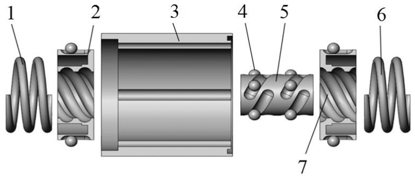
3D explosion of ball screw coupling.

Key parts of ball-screw-type compression–torsion coupling.
The working principle of 2D electro-hydraulic proportional directional valve is shown in Figure 4. The right valve chamber of the 2D direction valve is connected to the oil port P (system pressure) through the small hole a, the inner channel of the valve spool, and the small hole b, the section area of which is half the section area of the left valve chamber. The pressure of the left sensitive chamber e is controlled by two pairs of the low-pressure hole c, high-pressure hole d, and two small arch areas of the inner surface of the spool, which can form a half resistance bridge.
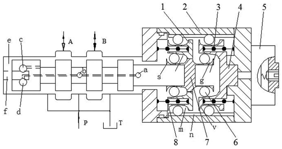
Schematic of ball-screw-type 2D electro-hydraulic proportional directional valve.
For the static state, the reset spring I and the reset spring II are in pre-tightening state, which effectively eliminates the gap between the ball and the raceway. Regardless of the fact that the friction and the hydrodynamic force of the valve port are omitted, the bow areas formed by the low-pressure hole c (or the high-pressure hole d) and the sensitive channel f are the same. The pressure of the left sensitive valve chamber e is half the P port pressure, so that the spool maintains the hydrostatic balance axially.
When the system is under normal working pressure, the working process of 2D electro-hydraulic proportional direction valve is shown in Figure 5. The valve core cannot be driven directly by the electromagnetic force due to the hydrodynamic effect, so the coil current is increased for causing the left thrust, and thus the steel ball rolls between the straight groove n and the straight slot v so that the B section of compression–torsion coupling is restrained by the radial direction, and it causes a displacement to the left

Motion diagram of ball-screw-type 2D electro-hydraulic proportional directional valve.
Similarly, when the current is reduced and the spring is restored to the right, the spool will move to the right. The flowchart of the control signal of the 2D electro-hydraulic proportional reversing valve is shown in Figure 6.
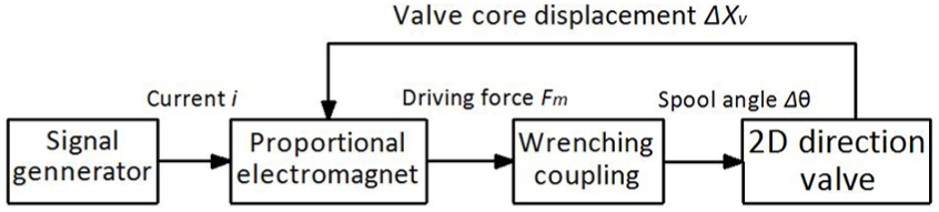
Control signal flowchart of ball-screw-type 2D electro-hydraulic proportional directional valve.
Mathematical model
Force torque analysis of the compression–torsion coupling
According to the function exchange principle, 13 assuming that the friction force in the compression–torsion coupling is ignored, the axial force torque conversion relation is as follows

where M is the torque output for the coupling, Fm is the force acting on the wedge by the proportional electromagnet, Rd is the effective radius for the transmission force of the center shaft, xm is the axial displacement of the compression–torsion coupling C, β is the angle between the chute and the vertical direction, and θ is the spool angle.
Analysis of pilot control oil-way
Assuming that the full bridge can be regarded as two differential half bridges, it is only necessary to study the pilot control of the half bridge. The flow rate in the pilot control stage is partly from the flow rate Q1 of the overlap area between the high-pressure hole and the sensitive channel, and the other part is the leakage volume Ql1 from the high-pressure hole to the sensitive channel. However, part of the outflow in the flow guidance level is the flow volume Q2 of the overlap area between the low-pressure hole and the sensing channels, and the other volume Ql2 is the leakage of the sensing channel to the low-pressure hole. The pilot control flow Qc is as follows

where


In equations (3) and (4), A1 and A2 are the intersecting area between the high- and low-pressure holes and the straight channel, that is, the overflow area of the pilot oil, which is shown in Figure 7.
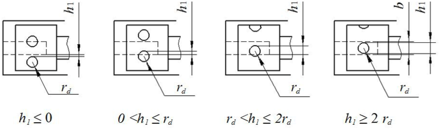
Overflow area of the pilot oil.
As a result, the overcurrent area A can be expressed as

Flow continuity equation
Assuming the friction force and the leakage between the valve shoulder and the valve port being ignored, the pressure of the sensitive cavity is equal to that of the valve, so the flow equation of the valve is
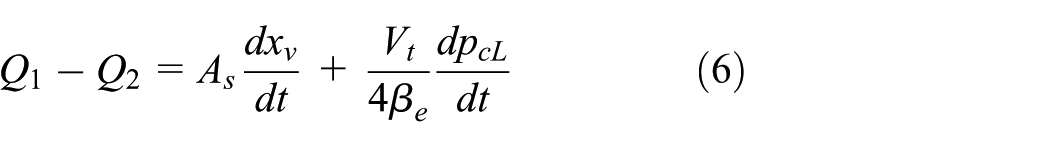
where As is the area of the shoulder of the valve core, βe is the volume elastic mode of the oil, and Vt is the sum of the volume of the sensitive cavity around the valve core.
Force balance equation of the spool
The force balance equation of the valve core is

where Bs is the total viscosity coefficient converted to the spool, including transient hydrodynamic damping and viscous damping, FL is the total force acting on the spool on the external load, ms is converted to the total mass on the spool, and KL is the hydrodynamic stiffness caused by steady-state hydrodynamic force.
Transfer function
Block diagram of closed-loop control of 2D directional valve can be derived from equation (8)

As shown in Figure 8, the closed-loop transfer function can be obtained using the diagram.

Transfer function block diagram of 2D valve.
Simulation analysis
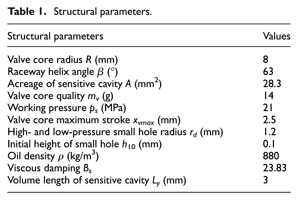
The governing equations of the dynamic performance of the 2D directional valve are constituted according to equations (2)–(8). The numerical simulation analysis of the 2D valve is made to verify the relationship between the structural parameters and performance. 14 The structural parameters of the 2D valve used in the simulation are shown in Table 1.
Structural parameters.
Analysis of step response characteristics
The step responses of the spool displacement xv are simulated for different parameters, such as high- and low-pressure small hole radius rd, system pressure ps, and the spool is rebalanced R. Notice that the proportional electromagnet displacement xm is considered as an input and the spool displacement xv is considered as the output. The simulation results are shown in Figures 9–12. From Figure 9, it can be seen that the step response time decreases with the increase in the radius of the high (low)-pressure hole. Figure 10 shows that the response time is reduced when the system pressure is increased. As shown in Figures 11 and 12, the response time increases with the increase in the effective driving force radius R and the angle β of the inclined slot. The simulation value has a good guiding significance for the experimental design and is helpful to find the optimal solution among the contradictory parameters.
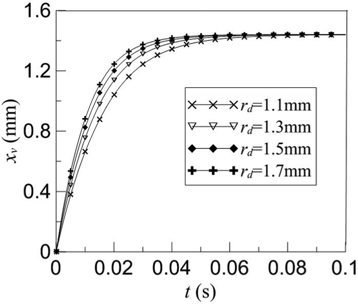
Step response via pressure hole.
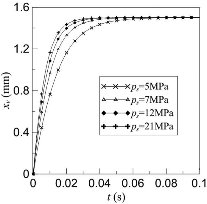
Step response via system pressure.

Step response via effective radius.

Step response via wedge slope angle.
The influence of the angle β of the inclined slot on the step response is more obvious, and the influence of the other parameters on the dynamic characteristics of the valve is similar to that of the space, and it is limited to the length of the space.
Frequency characteristic analysis
According to the mathematical model of the 2D valve, the open-loop control Bode diagram is shown in Figure 13. It is shown from the diagram that the natural frequency ωh of the 2D valve is equal to its amplitude crossing frequency ωc, and the crossing frequency is approximately equal to the open-loop amplification factor. And if the open-loop amplification factor is larger, the response speed is faster and the control precision is higher.

Bode diagram.
Experimental verification
Experiment setup
The experimental setup is shown in Figure 14 for validating the characteristics of the ball-screw-type 2D electro-hydraulic proportional directional valve. A 4WE10 valve is designed specially. Because the steady flow force of the 4WE10 valve is 180 N under the condition of 21 MPa, an Anyang Kaidi company GP45-4-A type proportional electromagnet is chosen (the rated output power is 80 N, insufficient to directly promote the valve movement). The experimental scheme is shown in Figure 15. Using the proportional control amplifier to superimpose different flutter signals of different amplitudes and frequencies, the displacements of the electromagnet and spool are detected by a high-resolution laser displacement sensor.

Image of prototype.

Measurement set-up for operation.
Experimental research on compression–torsion coupling
There is a certain gap between the ball and the raceway, so the pre-tightening force on both ends of the spring is set (it is about 15 N), which can effectively eliminate the pre-tightening force before the ball and raceway. In the experiment, it is found that the flutter compensation effect is best when the amplitude of the vibration is 30% and the frequency is 20 Hz. The experimental curve of input displacement and output displacement of the coupling is obtained, as shown in Figure 16. As shown in Figure 17, when the hysteresis is reduced to about 0.5%, the dynamic characteristics of the input and output displacements have good linearity. The experiment shows that the ball-screw-type compression–torsion coupling of the 2D electro-hydraulic proportional directional valve can work as normally as the direct moving direction valve without pressure.

Experimental curves of input and output displacements.

Dynamic experimental curve of input and output displacements.
Static experiment
A VS 4 flow meter is used in this experiment, and its range is 300 L/min. After adjusting the valve zero position, the chatter is added (the maximum amplitude is rated current and the frequency of triangular wave of the current control signal is 0.02 Hz), the cut-off valve is switched, and the high-pressure oil directly returns to the tank through the P port and the A port; as a result, the output flow of valve is measured by using the relation curve between input displacement and output displacement under different system pressure, as shown in Figure 18. The large flow rates of the valve are 7, 15, and 21 MPa. It achieves good characteristics, high pressure, and large flow control.

Experimental curves at the flow rates of (a) 7, (b) 15, and (c) 21 MPa.
Dynamic experiment
The direction of the cut-off valve is switched and then a certain flutter is added in the control signal of input sine wave current. The maximum amplitude is rated current, the frequency response increases gradually, and the P high-pressure oil directly returns to the oil tank through the T port; then the output flow of the valve is measured. The frequency response of the valve for different frequency sinusoidal signals can be obtained. The characteristics of phase frequency and amplitude frequency are shown in Figures 19 and 20, respectively. It can be seen that the valve has a wide bandwidth, the bandwidth for −3 dB and −90° is about 12 Hz, and the valve has good dynamic characteristics.
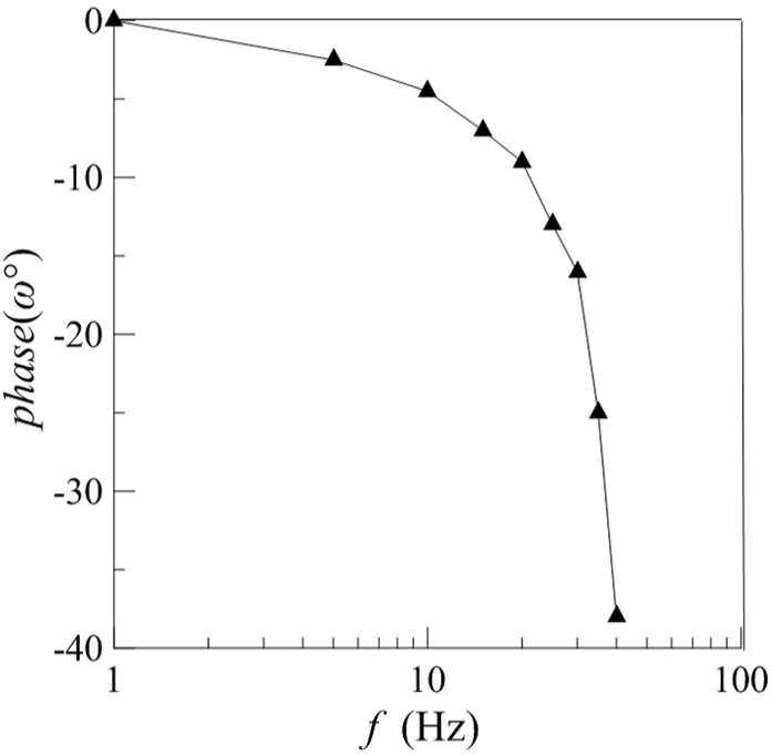
Experimental curves of phase response.

Experimental curves of frequency response.
Because the spool is an extension rod, it is more convenient to measure with laser displacement sensor, and there is no dynamic flow meter in the laboratory. The measured step response curve is shown in Figure 21. From the diagram, it can be seen that the step response time of the valve spool is about 0.45 s and there are no overshoot and low steady-state error, which shows that the 2D reversing valve has a faster response speed. The step response time of the proportional electromagnet is about 0.35 s.

Experimental curves of step response.
Conclusion
A ball-screw-type compression–torsion coupling is designed, which converts the linear displacement of the proportional electromagnet to the angular displacement of the 2D valve spool. After the valve core rotates, it produces axial displacement under the pressure difference of the two ends. When the pressure of the system is zero, the proportional electromagnet will axially drive the valve spool to realize the proportional control. Therefore, the 2D electro-hydraulic proportional directional valve has both direct and guided proportional valve functions, and the experimental results have also verified this conclusion.
The mathematical model of the valve is established using the theory of fluid control. The step response and the frequency characteristics of the valve are simulated and analyzed by MATLAB software. The simulation results show that the valve has good dynamic characteristics, which provides a theoretical basis for the design and optimization of the 2D valve.
The experimental results show that the valve can effectively overcome the influence of hydrodynamic force and frictional force on the state of pilot control and realize the proportional control of the axial displacement of the valve core. In particular, if the dynamic characteristics of the proportional electromagnet are not considered, the 2D valve itself has a fast dynamic response capability.
Footnotes
Appendix 1
Handling Editor: Ito Kazuhisa
Declaration of conflicting interests
The author(s) declared no potential conflicts of interest with respect to the research, authorship, and/or publication of this article.
Funding
The author(s) disclosed receipt of the following financial support for the research, authorship, and/or publication of this article: The research work presented in this paper was financially supported by the National Natural Science Foundation of China (Grant No. 51605430) and by the Hangzhou Science and Technology Information Survey Project (Grant No. 20161334M14).